Language selection

Search

Patent 2296249 Summary

Third-party information liability

Some of the information on this Web page has been provided by external sources. The Government of Canada is not responsible for the accuracy, reliability or currency of the information supplied by external sources. Users wishing to rely upon this information should consult directly with the source of the information. Content provided by external sources is not subject to official languages, privacy and accessibility requirements.

Claims and Abstract availability

Any discrepancies in the text and image of the Claims and Abstract are due to differing posting times. Text of the Claims and Abstract are posted:

  • At the time the application is open to public inspection;
  • At the time of issue of the patent (grant).
(12) Patent: (11) CA 2296249
(54) English Title: STEERING RESPONSIVE POWER BOOST
(54) French Title: SERVOCOMMANDE SENSIBLE A LA DIRECTION
Status: Expired and beyond the Period of Reversal
Bibliographic Data
(51) International Patent Classification (IPC):
  • B62D 11/00 (2006.01)
  • B62D 11/18 (2006.01)
(72) Inventors :
  • ANDERSON, LAWRENCE VERNON (United States of America)
  • SCHLETZBAUM, JOHN WAYNE (United States of America)
  • MAYFIELD, RONALD LEE (United States of America)
  • YODER, DENNIS ROYAL (United States of America)
  • WITTE, BENJAMIN MICHAEL (United States of America)
  • HOU, RAYMOND YIFEI (United States of America)
  • MISTRY, SANJAY ISHVARLAL (United States of America)
(73) Owners :
  • DEERE & COMPANY
(71) Applicants :
  • DEERE & COMPANY (United States of America)
(74) Agent: BORDEN LADNER GERVAIS LLP
(74) Associate agent:
(45) Issued: 2004-04-06
(22) Filed Date: 2000-01-19
(41) Open to Public Inspection: 2000-08-25
Examination requested: 2000-01-19
Availability of licence: N/A
Dedicated to the Public: N/A
(25) Language of filing: English

Patent Cooperation Treaty (PCT): No

(30) Application Priority Data:
Application No. Country/Territory Date
09/257,717 (United States of America) 1999-02-25

Abstracts

English Abstract


A steering control system for a tracked vehicle includes an engine driven
variable
displacement steering pump which drives a hydraulic motor. A control system
senses
steering wheel position, vehicle speed, engine speed and forward/reverse
vehicle direction.
As a function of these sensed inputs, a control signal is generated and is
used to control the
swashplate angle of an engine-driven variable displacement pump which drives a
steering
motor which drives a differential track drive mechanism. The control system
also
determines a ratio of motor speed to vehicle speed and generates a powerboost
signal
when the ratio exceeds a threshold value. The powerboost signal is
communicated to the
engine controller which causes the engine to increase its power output. This
modifies the
engine fuel delivery curve based on the steering system power requirement and
increases
the power available for turning the vehicle.


Claims

Note: Claims are shown in the official language in which they were submitted.

Claims
The embodiments of the invention in which an exclusive property or privilege
is
claimed are defined as follows:
1. A control system for a tracked vehicle having left and right tracks, an
engine
controlled by an electronic engine controller, the engine driving a
differential track drive
mechanism which turns the vehicle by driving the left and right tracks at
different speeds,
the control system comprising:
means for generating a powerboost ON signal when the vehicle is turning in a
non-
counter-rotational mode;
means for generating a powerboost OFF signal when the vehicle is not turning;
means for communicating the powerboost ON and powerboost OFF signals to the
electronic engine controller, the engine controller increasing a power output
of the engine
above a normal power level in response to the powerboost ON signal, and the
engine
controller decreasing a power output of the engine back to its normal level in
response to
the powerboost OFF signal.
2. The control system of claim 1, wherein:
the engine of the tracked vehicle drives a variable displacement pump which
drives a
steering motor which drives the differential track drive mechanism, and the
control system
comprises:
a motor speed sensor for generating a motor speed signal representing a speed
of
the steering motor;
a vehicle speed sensor for generating a vehicle speed signal;
means for calculating a speed ratio representing a ratio of motor speed to
vehicle
speed;
means for comparing the speed ratio to a threshold value; and
means for generating the powerboost ON signal if the speed ratio is greater
than the
threshold value.
3. The control system of claim 2, comprising:
means for generating the powerboost OFF signal if the speed ratio is less than
a
second threshold value.
4. The control system of claim 1, comprising:
means for generating of the powerboost OFF signal when the differential track
drive
mechanism is operating substantially in a purely counter-rotation mode.
5. The control system of claim 2, comprising:

means for generating the powerboost OFF signal if the vehicle speed signal is
near
zero.
6. A control system for a tracked vehicle having left and right tracks, an
engine
controlled by an electronic engine controller, the engine driving a variable
displacement
pump which drives a steering motor which drives a differential track drive
mechanism which
turns the vehicle by driving the left and right tracks at different speeds,
the control system
comprising:
a motor speed sensor for generating a motor speed signal representing a speed
of
the steering motor;
a vehicle speed sensor for generating a vehicle speed signal;
means for calculating a speed ratio representing a ratio of motor speed to
vehicle
speed;
means for comparing the speed ratio to a first threshold value;
means for generating a powerboost ON signal if the speed ratio is greater than
the
threshold value;
means for comparing the speed ratio to a second threshold value if the speed
ratio is
not greater than the threshold value; and
means for generating a powerboost OFF signal if the speed ratio is less than
the
second threshold value, the engine controller increasing a power output of the
engine in
response to the powerboost ON signal, and the engine controller causing the
engine to
produce a normal power output of the engine in response to the powerboost OFF
signal.

Description

Note: Descriptions are shown in the official language in which they were submitted.


CA 02296249 2000-O1-19
STEERING RESPONSIVE POWER BOOST
Background of the Invention
The invention relates to a control system for a tracked vehicle.
Tracked vehicles are steered by driving one track faster or slower than the
other and
significant power is required for such vehicles to turn. US patent No.
4,699,021 issued 13
Oct. 1987 to Waddington, describes an integrated power system for a tracked
vehicle driven
by a gas turbine, wherein fuel flow to the gas turbine engine is increased
when a directional
control is placed in a pivot steering or counter-rotation position. However,
This system does
not increase engine power during normal turning operation (non-counter-
rotation steering).
But, when a tracked vehicle turns under heavy load, the steering system uses
up most of
the engine power. For example, if a tracked vehicle is pulling an implement,
then, unless
engine power output is increased, during a turn there will be less power
available to operate
the implement. Under such a condition, the operator has to compromise with
respect to
either vehicle speed or implement depth while turning. Adjusting the implement
so that
adequate power remains for turning would result in wasted unused power during
more
prevalent straight ahead operation. Failing to provide adequate power for
turning may result
in lifting the implement during turns, changing the gear ratio or overloading
the engine.
Summary of the Invention
Accordingly, an object of this invention is to provide a tracked vehicle
control system
which increases engine power output during turning operation relative to the
engine power
during straight ahead operation.
This and other objects are achieved by the present invention, wherein a
tracked
vehicle includes an engine controlled by an electronic engine controller. A
control system
senses steering wheel position, vehicle speed, engine speed and
forwardlreverse vehicle
direction. As a function of these sensed inputs, a control signal is generated
and is used to
control the swashplate angle of an engine-driven variable displacement pump
which drives a
steering motor which drives a differential track drive mechanism. According to
the present
invention, the control system also determines a ratio of motor speed to
vehicle speed and
generates a powerboost signal when the ratio exceeds a threshold value. The
powerboost
signal is communicated to the engine controller which causes the engine to
increase its
power output. This modifies the engine fuel delivery curve based on the
steering system
power requirement. This allows increased power to be automatically available
for turning
the vehicle, thus increasing productivity and reducing the number of required
additional
operating controls while turning.

CA 02296249 2000-O1-19
Brief Description of the Drawings
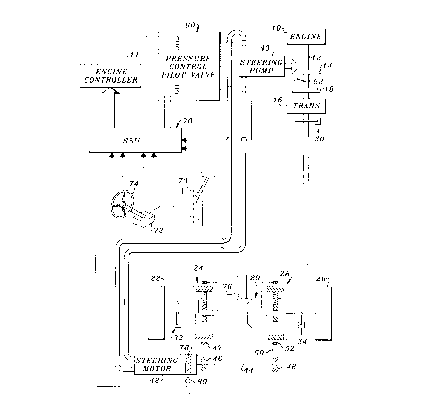
Fig. 1 is a simplified schematic diagram of a tracked vehicle drive and the
control
system of the present invention; and
Fig. 2 is a logic flow diagram of a power boost algorithm executed by a
microprocessor of the control system of FIG. 1.
Detailed Description
Referring to Fig. 1, an engine 10 of a tracked vehicle has an output shaft 12
which
drives a right angle gear 14 and a transmission 16 via a clutch 18. The engine
10 is
controlled by an electronic engine control unit 11. The transmission 16 drives
a final or right
angle drive 20, which drives a left track drive wheel 22 via left steering
planetary drive 24,
and a right track drive wheel 26 via right steering planetary drive 28. The
steering planetary
drives 24 and 28 are preferably such as described in US Patent No. 5,390,751,
issued 21
Feb. 1995 to Puetz et al., and assigned to the assignee of this application.
Additional
outboard planetaries (not shown), as provided on John Deere 8000 tractors, are
mounted
between the steering planetaries and the respective drive wheels, but are not
further
described because they are not directly involved in the steering responsive
power boost
function which is the subject matter of this application. A parking brake 30
is coupled to
shaft 18, and left and right service brakes 32, 34 are coupled to the left and
right drive
wheels 22, 26, respectively.
The right angle gear 14 drives a variable displacement steering pump 40, such
as a
75 cc, 90 series pump made by Sauer-Sundstrand. The pump 40, in turn, powers a
hydraulic fixed displacement steering motor 42, such as a 75 cc, 90 series
motor, also made
by Sauer-Sundstrand. The steering motor 42 drives, via a cross shaft 44 and
gear 46, a
ring gear 47 of left planetary drive 24, and via cross shaft 44, gear 48 and
reverser gear 50,
a ring gear 52 of right planetary drive 24.
The swashplate (not shown) of steering pump 40 is controlled by a pressure
controlled pilot valve or electronic displacement control (EDC) 60. The EDC is
preferably a
known two stage device with first stage including a flapper type valve and a
second stage
including a boost stage to the pump, such as is commercially available from
Sauer-
Sundstrand with minor modifications to the spool for cold weather and without
a manual
override function.
A rotation speed sensor 62, such as a commercially available mag pickup,
mounted
in proximity to the right angle drive 14, provides an engine speed signal to a
steering system
unit (SSU) 70. The solenoids of valve 60 are controlled by pump command
signals
(pump cmd) signals generated by SSU 70. The SSU 70 is communicated with the
engine
control unit 11.
2

CA 02296249 2000-O1-19
A steering wheel rotary position transducer 72, such as a rotary
potentiometer,
provides to SSU 70 a steering angle signal (steer angle) representing the
position, relative
to a centered position, of a spring centered, operator controlled steering
wheel 74.
A drive line rotation speed sensor 76, preferably a differential Hall-effect
speed
sensor such as used on production John Deere tractors, is mounted in proximity
to the final
drive 20, and provides to the SSU 70 a final drive speed, wheel or vehicle
speed signal. A
magnetic ring 78 is mounted for rotation with the motor 42, and a Hall-effect
transducer 80
mounted near the magnetic ring 78 provides to the SSU 70 a motor speed signal
and a
motor direction signal.
The SSU 70 includes a commercially available microprocessor (not shown) which
executes a power boost algorithm 100 which is illustrated by FIG. 2. The power
boost
algorithm 100 begins at step 102. Step 104 checks sensor 76 to determine if
the vehicle
speed is near zero or less than a small threshold speed, such as 2 kilometers
per hour
(kph). If it is, step 108 sets a speed ratio value to zero and directs the
algorithm to step 110.
If in step 104 the vehicle speed is not near zero, the algorithm proceeds to
step 106. Step
106 calculates a speed ratio value equal to a constant (100) times the
steering motor speed
(from sensor 80) divided by the vehicle speed.
After either steps 106 or 108, step 110 compares the speed ratio value to a
first
threshold or setpoint value, such as 30. If the speed ratio is greater than
the setpoint value,
the algorithm proceeds to step 116 which sets a boost flag to ON. If the speed
ratio in step
110 is not greater than the setpoint value, the algorithm proceeds to step 112
which
compares the speed ratio to a second setpoint or threshold value, such as 26.
If the speed
ratio in step 112 is not greater than the second setpoint value, the algorithm
returns to step
104. If the speed ratio in step 112 is greater than the second setpoint value,
the algorithm
proceeds to step 114 which sets the boost flag to OFF.
Step 118 then sends to the engine control unit 11 the appropriate boost ON or
boost
OFF signal as set in step 114 or 116 so that the engine control unit 11 will
increase or not
increase the power output of the engine 10 accordingly, and then returns
control to step
104. Thus, the algorithm 100 operates to increase the power output of the
engine 10 when
the vehicle is in a turn and when the ratio of steering motor speed to vehicle
speed exceeds
a certain threshold level. If this threshold level is exceeded, this increased
engine power
output will be maintained until the ratio drops below a second lower
threshold.
If the vehicle is in a purely counter-rotation or pivot steering mode, then
the vehicle
speed (sensed by sensor 76) will be near zero or less than a small threshold
speed, such as
2 kph, and steps 104, 108, 110, 112 and 114 will operate to generate a power
boost OFF
signal and there will be no engine power boost due solely to this algorithm.
It should be
3

CA 02296249 2000-O1-19
understood that the engine controller 11 will perform its normal function and
provide
sufficient fuel to the engine 10 so that the engine 10 can provide the power
necessary for
the counter-rotation of the drive wheels 22 and 26. However, the present
invention will
operate so that, during pure counter-rotation turning, there will be no extra
engine power
boost beyond that which is normally provided by the engine controller 11.
While the present invention has been described in conjunction with a specific
embodiment, it is understood that many alternatives, modifications and
variations will be
apparent to those skilled in the art in light of the foregoing description.
Accordingly, this
invention is intended to embrace all such alternatives, modifications and
variations which fall
within the spirit and scope of the appended claims.
4

Representative Drawing
A single figure which represents the drawing illustrating the invention.
Administrative Status

2024-08-01:As part of the Next Generation Patents (NGP) transition, the Canadian Patents Database (CPD) now contains a more detailed Event History, which replicates the Event Log of our new back-office solution.

Please note that "Inactive:" events refers to events no longer in use in our new back-office solution.

For a clearer understanding of the status of the application/patent presented on this page, the site Disclaimer , as well as the definitions for Patent , Event History , Maintenance Fee  and Payment History  should be consulted.

Event History

Description Date
Inactive: IPC from MCD 2006-03-12
Time Limit for Reversal Expired 2006-01-19
Letter Sent 2005-01-19
Grant by Issuance 2004-04-06
Inactive: Cover page published 2004-04-05
Inactive: Final fee received 2003-12-30
Pre-grant 2003-12-30
Notice of Allowance is Issued 2003-07-04
Letter Sent 2003-07-04
Inactive: Approved for allowance (AFA) 2003-06-16
Amendment Received - Voluntary Amendment 2001-05-09
Application Published (Open to Public Inspection) 2000-08-25
Inactive: Cover page published 2000-08-24
Inactive: First IPC assigned 2000-03-16
Letter Sent 2000-02-18
Inactive: Filing certificate - RFE (English) 2000-02-18
Application Received - Regular National 2000-02-18
All Requirements for Examination Determined Compliant 2000-01-19
Request for Examination Requirements Determined Compliant 2000-01-19

Abandonment History

There is no abandonment history.

Maintenance Fee

The last payment was received on 2004-01-05

Note : If the full payment has not been received on or before the date indicated, a further fee may be required which may be one of the following

  • the reinstatement fee;
  • the late payment fee; or
  • additional fee to reverse deemed expiry.

Patent fees are adjusted on the 1st of January every year. The amounts above are the current amounts if received by December 31 of the current year.
Please refer to the CIPO Patent Fees web page to see all current fee amounts.

Fee History

Fee Type Anniversary Year Due Date Paid Date
Registration of a document 2000-01-19
Application fee - standard 2000-01-19
Request for examination - standard 2000-01-19
MF (application, 2nd anniv.) - standard 02 2002-01-21 2002-01-18
MF (application, 3rd anniv.) - standard 03 2003-01-20 2003-01-17
Final fee - standard 2003-12-30
MF (application, 4th anniv.) - standard 04 2004-01-19 2004-01-05
Owners on Record

Note: Records showing the ownership history in alphabetical order.

Current Owners on Record
DEERE & COMPANY
Past Owners on Record
BENJAMIN MICHAEL WITTE
DENNIS ROYAL YODER
JOHN WAYNE SCHLETZBAUM
LAWRENCE VERNON ANDERSON
RAYMOND YIFEI HOU
RONALD LEE MAYFIELD
SANJAY ISHVARLAL MISTRY
Past Owners that do not appear in the "Owners on Record" listing will appear in other documentation within the application.
Documents

To view selected files, please enter reCAPTCHA code :


To view images, click a link in the Document Description column. To download the documents, select one or more checkboxes in the first column and then click the "Download Selected in PDF format (Zip Archive)" or the "Download Selected as Single PDF" button.

List of published and non-published patent-specific documents on the CPD .

If you have any difficulty accessing content, you can call the Client Service Centre at 1-866-997-1936 or send them an e-mail at CIPO Client Service Centre.


Document
Description 
Date
(yyyy-mm-dd) 
Number of pages   Size of Image (KB) 
Representative drawing 2000-08-21 1 14
Abstract 2000-01-18 1 23
Description 2000-01-18 4 204
Claims 2000-01-18 2 76
Drawings 2000-01-18 2 50
Courtesy - Certificate of registration (related document(s)) 2000-02-17 1 115
Filing Certificate (English) 2000-02-17 1 164
Reminder of maintenance fee due 2001-09-19 1 116
Commissioner's Notice - Application Found Allowable 2003-07-03 1 160
Maintenance Fee Notice 2005-03-15 1 172
Correspondence 2003-12-29 1 24