Note: Descriptions are shown in the official language in which they were submitted.
CA 02296338 2000-O1-18
WO 99/03524 PCT/US98/14697
1
REBREATHER SYSTEM WITH DEPTH DEPENDENT
FLOW CONTROL AND OPTIMAL POZ DETERMINATION
FIELD OF THE INVENTION
The present invention relates generally to diving systems and more
particularly to
closed circuit and semi-closed circuit rebreathers having two separate gas
sources with
variable delivery rates for controlling the oxygen partial pressure of the
breathing mixture
and for maximizing dive and minimizing decompression times.
BACKGROUND OF THE INVENTION
Traditionally, self contained underwater breathing apparatuses can be viewed
as
falling into two general categories; open circuit and closed or semi-closed
circuit. Open
circuit systems are typically recognized by the common term SCUBA and
represent the most
commonly used form of underwater breathing apparatus. Developed and
popularized by
Jacques Cousteau, open circuit scuba apparatus generally comprises a high
pressure tank
filled with compressed air, the tank coupled to a demand regulator which
supplies the
breathing gas to for example, a diver, at the diver's ambient pressure,
thereby allowing the
2 0 user to breathe the gas with relative ease.
Conventional open circuit self contained diving systems are very well
understood in
the art and have been developed over the past several years into a wide
variety of gas
delivery systems, configured for an equally wide variety of applications. For
example,
compressed air is used as a breathing gas in typical sport diving
applications, while one or
2 5 more artificial mixtures of gasses might comprise the breathing mixture
for diving operations
at depths greater than approximately 50 meters (150 feet).
While open circuit scuba apparatus is relatively simple, at least in its
compressed air
form, the equipment required is bulky, heavy and the design itself is
inherently inefficient in
its use of the breathing gas. Each exhaled breath is expelled to the
surrounding environment,
3 0 thus wasting all the oxygen which was not absorbed by the user during the
breath. This
inefficiency in breathing gas utilization normally requires a diver to carry a
large volume of
breathing gas, in order to obtain a reasonable dive time. For example,
conventional open
circuit scuba gear typically includes compressed air tanks having gas volumes
of about 80
cubic feet, and which weigh over 40 lbs.
3 5 As a diver descends, the ambient pressure increases approximately one
atmosphere for
every 30 feet of depth as is well known. Accordingly, gas consumption
increases rapidly
with depth. As a diver proceeds below approximately 150 feet, the increasing
ambient
pressure and thus the increasing pressure of the breathing gas, causes serious
physiological
-1-
CA 02296338 2000-O1-18
WO 99103524 PCT/US98/14697
1
problems, such as nitrogen narcosis and oxygen toxicity, which may have even
deadly
effects.
In addition, even short duration dives at depths greater than 100 feet require
a certain
amount of decompression time which must be pre-calculated in order to ensure a
sufficient
volume of breathing gas remains after the dive in order to accommodate
decompression.
Accordingly, while relatively simple and inexpensive, open circuit scuba
apparatus imposes a
number of practical limitations on both depth and dive time as a consequence
of its
construction and configuration.
The most common type of open circuit SCUBA apparatus is depicted in FIG. l and
is
of the open circuit demand-type which utilizes compressed air tanks in
combination with
demand regulator valves which provide air from the tanks on demand from a
diver 18 by the
inhalation of air. A compressed air supply tank 10 is coupled to a first stage
(high pressure)
regulator 12 which reduces the pressure of the air within the tank to a
generally uniform low-
pressure value suitable for use by the rest of the system. Low pressure air
(approximately
150 psi) is delivered to a second stage regulator 14 through a demand valve 16
in
conventional fashion. Compressed air, at the cylinder pressure, is reduced to
the diver's
ambient pressure in two stages, with the first stage reducing the pressure
below the tank
2 0 pressure, but above the ambient water pressure, and the second stage
reducing the gas
pressure to the surrounding ambient or water pressure. The demand valve is
typically a
diaphragm actuated, lever operated spring-loaded poppet which functions as a
one-way valve,
opening in the direction of air flow, upon movement of the diaphragm by a
diver's inhalation
of a breath.
2 5 The second form of self contained breathing apparatus is the closed
circuit or semi-
closed circuit breathing apparatus, commonly termed rebreathers. As the name
implies, a
rebreather allows a diver to "rebreathe" exhaled gas to thus make nearly total
use of the
oxygen content in its most efficient form. Since only a small portion of the
oxygen a person
inhales on each breath is actually used by the body, most of this oxygen is
exhaled, along
30 with virtually all of the inert gas content such as nitrogen and a small
amount of carbon
dioxide which is generated by the diver. Rebreather systems make nearly total
use of the
oxygen content of the supply gas by removing the generated carbon dioxide and
by
replenishing the oxygen content of the system to make up for that amount
consumed by a
diver.
3 5 Both types of rebreather systems mentioned above, comprise a certain few
essential
components; namely, a flow loop with valves to control the flow direction, a
counterlung or
breathing bag, a scrubber to absorb or remove exhaled COz, and some means to
add gas to the
-2-
CA 02296338 2000-O1-18
WO 99/03524 PCT/IJS98/14697
1
counterlung as the ambient pressure increases. Valves maintain gas flow within
the flow
loop in a constant direction and a diver's lungs provides the motive power.
A typical semi-closed circuit rebreather system is illustrated in FIG. 2 and
commonly
comprises a compressed gas cylinder 20 containing a specific gas mix having a
predetermined fraction of oxygen. The gas is provided to a flow loop 22,
generally
implemented by flexible, gas impermeable hoses, which are coupled between the
cylinder 20
and a flexible breathing bag 24, sometimes termed a counterlung. A pair of one-
way check
valves 26 and 28 are disposed in the flow loop such that the gas flow within
the loop is
maintained in a single direction (clockwise in the illustration of FIG. 2). An
exhaled breath
would thus enter the counterlung, increasing the pressure therein, and pass
through one-way
check valve 26 and move through some device means to remove excess carbon
dioxide from
the breathing gas, such as a COz canister 30, and thereby return to the
counterlung through
one-way check valve 28. The check valves thus maintain the gas flow in a
constant direction,
while the diver's lungs move the gas through the COZ canister in the system.
The gas mix is
introduced into the flow loop at a flow rate calculated to maintain the oxygen
needs of a
particular diver during the dive. Gas is introduced to the flow loop at a
constant fixed flow
rate through a valve 32 coupled between the flow loop and the gas cylinder 20.
As the
2 0 breathing gas mix is recirculated, some of the oxygen is necessarily
consumed and COz is
absorbed, thus perturbing both the total volume and the mix of the gas. A
portion of the
oxygen is consumed during recirculation, so the diver necessarily breathes a
mixture with a
lower oxygen concentration than that of the gas mix. Since the amount of
oxygen supplied
to the system depends on a diver's activity level (oxygen consumption rate},
care must be
2 5 taken to take activity into account as well as selecting the gas mixture
composition for a
particular diving depth.
A more efficient type of rebreather system is the closed circuit rebreather,
illustrated in
simplified form in FIG. 3. Closed circuit rebreathers are generally more
sophisticated and
effective in their maintenance of oxygen levels in the flow loop. Nonetheless,
they share
3 0 common components with semi-closed circuit rebreather systems such as that
depicted in
FIG. 2. The main contrast between fully closed and semi-closed circuit
rebreather systems is
that the closed circuit rebreather, as configured, provides a source of pure
oxygen to the flow
loop and introduces oxygen to the recirculating gas in an amount ideally equal
only to that
consumed by a diver such that system mass is conserved. The oxygen level (more
correctly
3 5 the oxygen partial pressure) is monitored electronically by an oxygen
sensor (34 in FIG. 3)
whose output is evaluated by a processing circuit (36 of FIG. 3) which, in
turn, controls an
electrically operated solenoid valve so as to add oxygen to the system when
the oxygen
sensor indicates it is being depleted. It should be noted, that closed circuit
rebreathers only
-3-
CA 02296338 2000-O1-18
WO 99/03524 PCT/US98/14697
1
introduce gas to the system when the oxygen sensor 34 indicates the need for
additional
oxygen or as ambient pressure increases during descent and the addition of
diluent is required
to prevent the collapse of the counterlung. Oxygen is added in "pulses" in
contrast to the
steady-state flow of the semi-closed circuit system and is required to be
constantly
monitored. Diluent is added by a demand valve in the counterlung that is
activated as the
counterlung collapses because of increasing ambient pressure.
It should likewise be noted that once a particular oxygen partial pressure has
been
established in a closed circuit rebreather system, this partial pressure of
oxygen is maintained
by operation of the oxygen sensor 34 and processing circuit 36, regardless of
a diver's
external environment, and any changes thereto.
Partial pressure of oxygen in a particular breathing gas mixture may be
understood as
the pressure that oxygen alone would have if the other gasses (such as
nitrogen) were absent
from the gas. The physiological effects of oxygen depend upon this partial
pressure in the
mix and serious consequences result from oxygen partial pressures that are too
high; e.g.,
oxygen becomes increasingly toxic as the partial pressure increases
significantly above the
oxygen partial pressure found in air at sea level (0.21 atmospheres), as well
as too low.
Where the oxygen partial pressure is too low, a diver would not necessarily
experience any
2 0 discomfort or shortness of breath, and in many cases may not even be aware
of the shortness
of oxygen until unconsciousness is imminent. In a relatively short period of
time, depending
in turn on the volume of a counterlung, the diver would become unconscious and
eventually
die from hypoxia. The diver would experience very little discomfort, and in
fact may feel
rather euphoric. This euphoria is a typical and characteristically dangerous
aspect of
2 5 hypoxia.
On the other hand, serious physiological effects may result from too much
oxygen
leading to various forms of what might be termed oxygen poisoning. There are
several major
forms of oxygen poisoning but two in particular have a bearing on the
operational
configuration of various rebreather systems; central nervous system toxicity
(CNS) and
3 0 pulmonary or whole-body oxygen poisoning. Almost any rebreather system
that includes an
oxygen supply component is capable of delivering excess oxygen to a diver.
Excess oxygen
is defined in this case as oxygen partial pressure greater than specific
tolerable limits; the
most important limit being that of CNS oxygen toxicity. CNS limits, which
define the
oxygen partial pressure levels that can be tolerated for various durations
depending on the
3 5 degree of oxygen excess, are defined in the 1991 National Oceanographic
and Atmospheric
Administration (NOAA) diving manual and are well understood by those skilled
in the art.
CNS poisoning becomes a significant consideration as the partial pressure of
oxygen exceeds
a generally accepted limit of 1.6 atmospheres. CNS toxicity gives rise to
various symptoms,
-4-
_..... T.
CA 02296338 2000-O1-18
1
WO 99/03524 PCT/US98/14697
the most serious of which are convulsive seizures, similar to those
experienced during an
epileptic fit. These seizures generally last for about 2 minutes and are
followed by a period
of unconsciousness.
If a level of 1.6 atmospheres is not exceeded, then the concern becomes one of
pulmonary or whole body toxicity rather than CNS. Pulmonary oxygen toxicity
results from
prolonged exposure to oxygen partial pressures above approximately 0.5
atmospheres and the
consequences of excessive exposure include lung irritation, which may be
reversible, and
some lung damage which is not.
It will be apparent from the foregoing, that the partial pressure of oxygen in
a
breathing gas mixture should be kept to a value in the range of from about
0.21 atmospheres
to about 1.6 atmospheres. Further, in the absence of pulmonary oxygen toxicity
considerations, the optimum choice of the partial pressure of oxygen is the
maximum value
for which CNS toxicity poses no threat, i.e., 1.6 atmospheres. This is because
maximizing
the oxygen partial pressure to the highest practical limit has the effect of
minimizing the
diluent partial pressure and, minimizing diluent physiological uptake which
leads to the need
for decompression. Accordingly, to the extent that oxygen partial pressure is
increased,
decompression times are correspondingly decreased. However, for long duration
dives or
multiple repetitive dives, pulmonary oxygen toxicity (rather than CNS)
presents additional
limitations that could be avoided by a choice of a lower partial pressure of
oxygen. This
choice depends on well known pulmonary toxicity limitations, breathing gas
tank capacity,
and decompression considerations.
Thus, it will be seen that there is no one specific partial pressure of oxygen
in a
2 5 breathing gas that is optimal for all conditions at all depths. One set of
factors would tend to
indicate that a relatively higher partial pressure of oxygen is preferred,
while another set of
factors would tend to indicate that this is not always the case.
Typical of prior art systems is a mixed-gas, closed circuit rebreather
disclosed in U.S.
Patent No. 4,939,647 to Clough et al. The Clough et al. system is based on a
conventional
Rexnord CCR 155-type closed circuit rebreather comprising a supply of
compressed inert gas
and a supply of oxygen in separate source bottles. Inert gas is fed into the
system's breathing
loop by a demand regulator in order to maintain a loop volume with increasing
depth, while
oxygen is added to the breathing loop as it is consumed by a diver. Oxygen
partial pressure
in the loop is electronically monitored and maintained to a pre-set level
below the CNS
3 5 threshold. The system includes three oxygen sensors, operating in a
majority-vote
configuration which provides the sensing function for determining oxygen
partial pressure
within the loop. Oxygen partial pressures are adjustable, depending on the
dive profile
chosen, but once a particular value has been pre-set, that value is maintained
unless
-5-
CA 02296338 2000-O1-18
WO 99/03524 PCTNS98/14697
1
affirmatively readjusted. As a result, the Clough et al. system results in
unnecessary
restrictions in a dive profile.
Similar rebreather systems are described in U.S. Patent No. 3,727,626 to
Kanwisher et
al. and U.S. Patent No. 4,236,546 to Manley et al. The systems described are
both closed
circuit-type rebreathers that include electronics for maintaining oxygen
partial pressures in a
breathing loop at a specific, pre-set value.
The net result of a pre-set value of Poi can result in a reduction of dive
time and an
increase in unproductive decompression times. The objective of the present
invention is to
prevent these limitations.
SUMMARY OF THE INVENTION
A semi-closed circuit rebreather system in accordance with the present
invention,
provides a breathing gas mix to a diver in accordance with flow rates that
maintain oxygen
partial pressures within a specific, pre-set range, where the flow rates are
determined solely
as a function of the surrounding ambient pressure (depth). The semi-closed
circuit rebreather
system comprises an oxygen rich gas source and a diluent gas source,
configured to provide a
breathing gas mix to a flow loop including a counterlung. The oxygen rich and
diluent gas
2 0 sources each comprise a particular, different, oxygen fraction, and first
and second flow
control valves are coupled between the gas sources and the flow loop. Each
flow control
valve has a variable flow rate and adaptively adjusts the flow rate of its
respective gas source
so as to maintain partial pressure of oxygen within the counterlung within the
pre-determined
range, solely as a function of depth.
2 5 In one aspect of the invention, the oxygen rich gas source comprises pure
oxygen
having an oxygen fraction of I Ø The diluent gas source comprises compressed
air, having
an oxygen fraction of 0.21. Flow rates of the oxygen and air sources are
adaptively adjusted
as a function of depth in accordance with an algorithm defined in terms of
minimum and
maximum oxygen consumption rates, minimum and maximum oxygen partial
pressures, the
3 0 oxygen fraction of the oxygen rich and diluent gas sources, and depth.
Oxygen consumption,
fraction, and partial pressure are pre-determined; depth provides the only
variable, such that
the algorithm defines flow rates solely in terms of depth.
In yet a further aspect of the present invention, a closed circuit rebreather
system is
disclosed and includes an oxygen sensor, coupled to a signal processing
circuit, capable of
3 5 receiving an ambient pressure signal from the sensor, and providing
control signals to flow
valves to maintain oxygen partial pressure at a specific value determined in
accordance with
an analysis of tank capacity, no-decompression time at depth, and pulmonary
toxicity limits
to construct a dive profile giving maximum dive time. Optimal solutions for
oxygen partial
-6-
__ __._._. ._.._~_.~__ . _. ___.___.. ..... . T _ _._ _...
CA 02296338 2000-O1-18
WO 99/03524 PCT/US98/14697
pressure are calculated in accordance with an algorithm which equates a
pulmonary toxicity
time limit to a tank capacity time limit, with a no-decompression time at
depth providing an
S outer bound. In accordance with the invention, specific oxygen partial
pressure values e.g.,
0.5 and 1.6, are chosen as limiting values.
BRIEF DESCRIPTION OF THE DRAWINGS
These and other features, aspects and advantages of the present invention will
be more
fully understood when considered with respect to the following detailed
description,
appended claims, and accompanying drawings, wherein:
FIG. 1 is a semi-schematic generalized block level diagram of an open circuit
breathing apparatus in accordance with the prior art;
FIG. 2 is a semi-schematic generalized block level diagram of a semi-closed
circuit
rebreather system, in accordance with the prior art;
FIG. 3 is a semi-schematic generalized block level diagram of a closed circuit
rebreather system including an oxygen rich breathing gas supply tank, diluent
gas supply
tank, and an oxygen sensor, in accordance with the prior art;
FIG. 4 is a semi-schematic generalized block level diagram of a semi-closed
circuit
2 0 rebreather system in accordance with practice of principles of the
invention;
FIG. 5 is a simplified graphical representation of oxygen and diluent flow
rates plotted
as a function of depth and incorporating wide limits of oxygen consumption, in
accordance
with practice of principles of the invention;
FIG. 6 is a simplified graphical representation of oxygen and diluent flow
rates
2 5 plotted as a function of depth and incorporating narrow limits of oxygen
consumption, in
accordance with practice of principles of the invention;
FIG. 7 is an exemplary, simplified graphical representation of critical depth
at which
oxygen partial pressure exceeds 1.6 plotted as a function of the descent rate;
FIG. 8 is an exemplary simplified graphical representation of dive time in
minutes
3 0 plotted as a function of oxygen partial pressure, with No D times plotted
at various depths for
various values of oxygen partial pressure;
FIG. 9 is an exemplary simplified graphical representation of pulmonary
toxicity
limits superposed on the graphical representation of dive time and oxygen
partial pressure of
FIG. 8;
3 5 FIG. I 0 is an exemplary simplified flow chart which depicts a method for
determining
a dive profile such that bottom time, No D time and oxygen toxicity time
limits may be
optimized;
CA 02296338 2000-O1-18
1
WO 99/03524 PCT/US98/14697
FIG. 11 is a semi-schematic generalized block level diagram of a closed
circuit
rebreather system in accordance with practice of principles of the invention;
DETAILED DESCRIPTION OF THE INVENTION
FLOW RATE DETERMINATION
The primary limitation of conventional semi-closed rebreather systems lies in
the fact
that the flow loop and counterlung are supplied with breathing gas comprising
a fixed oxygen
proportion supplied at a constant mass flow. As is well understood by those
having skill in
the art, since the breathing gas mixture is provided with fixed proportions,
the oxygen partial
pressure of the supplied gas will necessarily increase with depth.
Accordingly, it is necessary
for a diver to strictly limit his depth in order to avoid the risk of Central
Nervous System
(CNS) oxygen toxicity, which occurs for oxygen partial pressures in excess of
1.6
atmospheres. Constant mass flow semi-closed circuit rebreather systems deliver
gas at a
much greater rate than necessary at shallow depths.
In accordance with practice of the present invention, the rebreather system,
which will
be described in detail below in connection with FIG. 4, is constructed as a
semi-closed circuit
2 0 rebreather, but unlike existing semi-closed circuit rebreather systems
comprising a single
breathing gas source, the system according to the invention requires two gas
sources. The
first gas source comprises a tank containing oxygen or an oxygen enriched gas
having an
oxygen fraction of from about 0.60 to about 1Ø The second gas source
comprises a tank
filled with a diluent gas having a lower oxygen content or none. The diluent
gas may be air,
with an oxygen fraction of 0.21, a suitable inert gas, or a custom diluent gas
mix such that the
oxygen fraction of the diluent gas may vary anywhere from about 0.0 to about
0.21. As will
be described in connection with the rebreather of the invention, below, each
gas source or
supply tank comprises an independent flow control valve, in order to achieve
separate and
independent flow rates specified by an algorithm defined in terms of depth
(external ambient
pressure), minimum and maximum allowable values of oxygen partial pressure
(POZ) and
minimum and maximum expected values of oxygen consumption.
Minimum and maximum allowable values of POZ range from between 0.21 and about
1.6 atmospheres, the lower limit having been determined by the need to avoid
hypoxia, the
upper limited determined by the CNS oxygen toxicity safety limit. In addition,
minimum and
3 5 maximum expected values of oxygen consumption are set, in accordance with
the invention,
at a range of from between 0.5 to about 3.0 standard liters per minute (SLM).
This range of
oxygen consumption values has been generally empirically determined to be
suitable for use
by most divers over most operating conditions.
_g_
_ T. _... .
CA 02296338 2000-O1-18
WO 99/03524 PCT/US98/14697
1
The minimum and maximum values of oxygen partial pressure and expected values
of
oxygen consumption given above will be understood to be suitable for purposes
of
illustration, but are not necessarily hard limits in any sense. Indeed, it is
possible to reduce
the minimum allowable value of POZ of from 0.21 atmospheres to about 0.14
atmospheres
and still retain sufficient oxygen concentration in the breathing gas mixture
to avoid hypoxia.
This reduced POZ value is in accordance with United States Air Force safety
standards which
allow air crew to breathe air at ambient pressure for altitudes up to 3048
meters, before going
on to a source of pure oxygen. Accordingly, it will be understood that while
useful for
describing and setting the bounds of the present invention, the actual
specific values of
minimum and maximum POZ and oxygen consumption may vary without violating the
spirit
and scope of the present invention. Moreover, as will be brought out in detail
in the
discussion below, the oxygen consumption values of 0.5 to 3.0 SLM are
significantly wider
than those practicably obtainable by an experienced diver. These wide ranges
of oxygen
consumption are posed in the interest of universality of application, but will
be seen to be
reducible.
Prior to considering a dynamic analysis of the flow loop POZ from two tanks
with
different oxygen fractions and independent flow controls, it is necessary to
reconsider the
2 0 oxygen partial pressure in the flow loop as a function of external ambient
pressure, i.e.,
depth. However, in order to define the algoritlun, it is necessary to return
to first principles.
In rebreather systems, it is well known that ambient pressure increases as the
diver
descends and the pressure in both the diver's lungs and the rebreather flow
loop will increase
with depth. While a rebreather is a dynamic system, in that the counterlung
expands and
2 5 contracts as a diver inhales and exhales, the principle underlying the
interchange of gas
between the diver's lungs and the counterlung is a quasi-steady state flow of
gas from the
supply tanks into the rebreather system, a flow of excess gas from the
rebreather system to
the surrounding ambient and extraction of oxygen from the flow loop as it is
consumed by a
diver. Additionally, it will be recognized that the minimum counterlung oxygen
content will
3 0 occur when a diver's oxygen consumption rate is at a maximum, and the
maximum
counterlung oxygen content will occur when the diver's oxygen consumption is
at a
minimum. It remains then to evaluate the quasi-steady state gas flow in the
flow loop. The
basic governing equations for this underlying process may be given by
3 5 PAnraVFL MFL(R~II1FL~TF.L
_g_
CA 02296338 2000-O1-18
1
WO 99/03524 PCT/US98/t4697
Where the terms may be defined as follows:
V~, is the volume of the flow loop, including the counterlung in units of
liters.
POZ VFL =Moz~R l m o2'T FL
MFL is the total mass of gas within the flow loop in units of grams.
Mo is the mass of oxygen in the flow loop in units of grams.
Z
mn is the nondimensional molecular weight of the gas mixture.
mo is the nondimensional molecular weight of oxygen (32).
z
T~, is the mean temperature in degrees Kelvin (K°).
PA,~,~ is the ambient pressure.
As well understood in the art, P,~"~~ is related to depth, D, through the
expression PpMa
= 1 + D/DAT~,, where both D and D~TM are expressed in feet of water and DATM
is the depth at
which the ambient pressure will have increased by 1 atmosphere (for sea water
DpTM = 33
feet).
2 0 The algorithm requires that the partial pressure of Oxygen (PO,) be
bounded by the
maximum POZ allowable for prevention of Central Nervous System (CNS) toxicity
and the
minimum POZ required to prevent hypoxia. Typical values for purposes of
illustration will be
taken to be 1.6 and 0.21 atmospheres, respectively. Prior to imposing these
constraints on the
system, it will first be necessary to evaluate the conservation of total mass
and oxygen in the
2 5 flow loop. This evaluation is straight-forward and involves
differentiating equations 1 and 2
and accounting for the mass flow into and out of the rebreather flow loop.
With regard to mass flow into and out of the flow loop, it should be
understood that if
mass is being added to the system at a greater rate than it is being consumed,
the volume of
the flow loop does not change, i.e., dV~/dt = 0. In addition, it will be
recognized that the
3 0 quantity dPA,"~/dt, may be expressed as DR/33, where DR is the well-
recognized descent rate
and is expressed in feet per minute such that DR/33 has units of atmospheres
per minute.
Following differentiation, the terms are rearranged and volumetric flow rates
are
expressed in STPD units, i.e., Standard Temperature (0 degrees C), Pressure (1
atmosphere)
and Dry. In these terms, and neglecting temperature differences, the resultant
equation may
3 5 be expressed, in simplified form, as:
PArraVFL(dPozldt'=F~ZP~BV~Z~'FAIRPAMBvAIR ParrB~2 Po2 ~Voz+VAra ~2 VFL~DRl33~)
-10-
_ ._.._._.__..~.._._~_~ _.__~~_.__ ..__.. T_
CA 02296338 2000-O1-18
WO 99/03524 PCT/US98/14697
1
Where tank flow rates, Vo2 and VA,R, and the rate of oxygen consumption, O2,
are now
expressed in standard liters per minute (SLM).
Removing common terms and grouping flow rate coefficients, the final form of
the
primary governing equation may be expressed, in simplified form, as:
PAMBVFL(dPOz/dt~=VOZ~FOZP~B-POZ'+VAIR(FAIRPAMB Po2~ ~2f PAMB
Poz~+P02VFL\DR/33,
A key feature of the present invention is the requirement that when the oxygen
partial
pressure exceeds the maximum, POZ in the flow loop will be reduced. This is
equivalent to
requiring that dP02/dt<0 if and when POZZ POz maX (1,6 atmospheres). In
addition, the key
feature of the invention requires that oxygen partial pressure increases if
partial pressure is
less than or equal to the minimum allowed. In a similar manner to the maximum
case above,
this is equivalent to requiring that dP02/dt>0 if and when PO,_<POZ°"".
Both of these
conditions will be satisfied if equality is imposed for the minimum and
maximum oxygen
consumption rate in accordance with the following equations:
2 0 EQUATION 5
Vo2( FozPAnrB Po~) +VAIR( FAIRPArrB Po2~) -~z I~ j',~a 1'0~) -~'o2~VFyDR/33)
2 5 EQUATION 6
V ~ F P _ pMINI +V ~ F P -PMrNI =O~ P -PMINI -PMINV (DR/33)
OZ OZ AMB OZ AIR AIR AMB O2 2 ,~yB O J O
z 2 FL
For specified values of OZ""N, OZ"~~, pO2M'~, and POZ"'''"', these equations
are solvable
30 for required tank flow rates as a function solely of depth and its rate of
change during a
diver's descent or ascent. In accordance with the present invention, the terms
of equations 5
and 6 may be rearranged such that the flow rates from the oxygen and diluent
tanks are
expressed solely in terms of coefficients, in turn depending solely upon the
oxygen fraction
of the gas in either tank, the maximum and minimum allowable oxygen partial
pressure, the
35 maximum and minimum oxygen consumption rate and the ambient pressure, or
depth. The
governing equation for the algorithm of the present invention is as follows:
-11-
CA 02296338 2000-O1-18
WO 99/03524 PCT/US98/14697
1
EQUATION 7
VoZ=~CE-BF~/(AE-BD~ and VAIR=(AF-CD~/~AE-BD~
where
- _ MAXI
A F'oz PnMS Po JZ
_ MAx
B=( FAIRPAMB
'
C=CMI~ pas po~~ po~VFL~DRl33~
_ MINI
D F'o2 pane Po JZ
35 = _ MINI
E F.a rx P.~Ma
F=Cz ~ PaMS-Po rNl -Po INVFZ,~DRl33~
where OZMiN' OZMnx~ pO2M~N and P02"'p''~ are specified design parameters with
typical values
2 0 of 0.5, 3.0, 0.21 and 1.60 respectively, and where the oxygen fraction of
the various supply
tanks ( F'o2 and FA) may be chosen by a user and may comprise any value
consistent with a
suitable solution of the governing equation. Preferably, the oxygen fraction
of the two
supply tanks will have typical values of from about 0.21 to about l .0,
representing air and
pure oxygen respectively.
SEMI-CLOSED CIRCUIT EMBODIMENT
A particular example of equilibrium (constant depth} flow rates derived from
the
governing equation 7 is depicted in FIG. 5, and typical values for the
equilibrium flow rates
and the resultant POZ for various rates of oxygen consumption are given in the
following
3 0 Table I .
-12-
... ~.....,_..._ _....,__. . _.. ..... T.. ..
CA 02296338 2000-O1-18
WO 99103524 PCTNS98/14697
1
TABLE 1
DEPTH VA VT OZ = 0.5 OZ = 1.25 OZ = 3.0
20 0.01 3.00 1.60 1.60 0.2I
40 1.26 2.84 1.60 1.44 0.21
60 2.57 2.62 1.60 1.37 0.21
80 3.90 2.38 1.60 1.33 0.21
100 5.24 2.13 1.60 1.30 0.21
120 6.60 I.86 1.60 1.28 0.21
140 7.96 1.59 1.60 1.27 0.21
160 9.33 1.32 1.60 1.26 0.21
180 10.69 1.04 1.60 I.25 0.21
200 12.06 0.76 1.60 1.25 0.21
220 13.43 0.48 1.60 1.24 0.21
240 14.81 0.20 1.60 1.24 0.21
260 16.18 0.00 I.64 1.28 0.27
280 17.55 0.00 1.77 1.42 0.45
300 18.93 0.00 1.90 1.56 0.62
320 20.30 0.00 2.03 1.69 0.78
The values in both Table 1 and the graph of FIG. 5 have been calculated using
a first
tank filled with pure oxygen and a second tank filled with air. Minimum and
maximum
values of POZ were chosen to be 0.21 and 1.6 respectively, while minimum and
maximum
values of the oxygen consumption rate were chosen to be 0.5 and 3.0,
respectively. From
3 0 FIG. 5, it can be seen that the flow rates for the oxygen tank will be a
maximum of about 3
liters per minute at shallow depths (about 20 feet) and then diminish to a
value of less than 1
liter per minute as the depth approaches 200 feet. The accompanying air tank
will experience
no flow for depths shallower than about 20 feet and exhibit an approximately
linearly
increasing flow rate to a value exceeding 10 liters per minute at a depth of
about 170 feet.
3 5 A particular behavioral characteristic of the algorithm of the present
invention occurs
at depths in excess of about 250 feet, as can be seen in Table 1. For the
minimum oxygen
consumption rate of 0.5 liters per minute, the maximum POZ requirement (I .6
atm) is
exceeded beyond a depth of about 255 feet. The reason for this is clearly
evident when it is
-I3-
CA 02296338 2000-O1-18
WO 99/03524 PCT/US98/14697
1
recognized that the diluent tank (in this case air) contains a fixed minimum
fraction of
oxygen (in this case 0.21 ) whose partial pressure increases with depth in
conventional
fashion. At the crossover point of 255 feet, the solution to the governing
equation would call
for a negative flow rate from the O, supply canister, and since this is
physically impossible,
OZ reduces to 0 which leaves a single parameter, i.e., the VA,~. Of particular
note is the fact
that for more realistic rates of minimum oxygen consumption, i.e., rates in
excess of I .25
liters per minute, POZ rates in excess of the POz maximum occur only at depths
greater than
300 feet as depicted in Table 1.
TABLE 2
DEPTH VA VT Oz =1 Oz =1.5 OZ = 2.0
0.00 2.00 1.60 1.59 0.21
15 40 0.50 1.94 1.60 1.27 0.21
60 1.03 1.85 1.60 1.16 0.21
80 1.56 1.75 1.60 1.10 0.2I
100 2.10 1.65 1.60 1.06 0.21
120 2.64 1.54 1.60 1.03 0.21
20
140 3.18 1.44 1.60 1.02 0.21
160 3.73 1.33 1.60 1.00 0.21
180 4.28 1.22 1.60 0.99 0.21
200 4.82 1.10 1.60 0.98 0.21
2 220 5.37 0.99 i .60 0.98 0.21
5
240 5.92 0.88 1.60 0.97 0.21
260 6.47 0.76 1.60 0.97 0.21
280 7.02 0.65 1.60 0.96 0.21
3 300 7.57 0.54 1.60 0.96 0.21
0
320 8.12 0.42 1.60 0.95 0.21
Moreover, as can be seen with reference to Table 2, when the range of oxygen
consumption
is bounded by a more restrictive minimum of 1.0 liters per minute to a maximum
of 2.0 liters
3 5 per minute, flow rates from both the O~ and diluent tanks are
substantially reduced,
particularly for the air or diluent tank. Indeed, it can be seen from Table 2
that for a more
constrained range of oxygen consumption, the PO, max requirement of the
present invention
is satisfied for all depths down to and exceeding 330 feet. Thus, a particular
diver may
-14-
~..
CA 02296338 2000-O1-18
WO 99/03524
1
PCT/US98/14697
monitor and record their rates of oxygen consumption and use their local
minima and maxima
as upper and lower boundaries for the Oz consumption term in the governing
equation of the
present invention. For a particular diver able to operate within more
restrictive oxygen
consumption limits, dive time is greatly increased for a particular tank size
because of the
significantly reduced flow rates from the oxygen and diluent tanks. This
resultant
performance increase, is depicted in FIG. 6.
Although the preceding analysis was performed in terms of a quasi-steady state
(constant depth) regime, the algorithm of the present invention is more than
suitable for
adaptation for evaluating transient behavior, such as during ascent and
descent. Since the
initial flow from the air or diluent tank is nominally zero at shallow depths
(less than about
feet) the initial oxygen content of the flow loop (the counterlung) will be
equal to that of
the oxygen rich tank, i.e., 1.0 for FT = 1Ø During descent, certain critical
depths are reached
15 at which the maximum allowable PO~ is exceeded because of transient
effects. One
particular solution, in accordance with the invention, is to add diluent gas
from the diluent or
air tank to counter act the tendency of the counterlung to collapse because of
the increased
ambient pressure as a diver descends. Adding gas to the counterlung is
achieved
mechanically by providing a demand regulator within the counterlung that
introduces gas
20 from the diluent or air tank by controlling the diluent or air flow valve
in a manner directly
proportional to the descent rate. Lever-operated down stream demand regulators
are
particularly suitable for this application since the material of the
counterlung provides the
same function as the breathing diagram in a conventional second stage SCUBA-
type demand
regulator well known in the art. The collapsing material of the counterlung
activates a lever
2 5 which in turn, displaces a poppet from a low-pressure air hose coupled to
a step-down
pressure regulator connected to the air or diluent tank. As the poppet
displaces from the flow
path, air or diluent gas is introduced into the counterIung which expands in
response, thus
relieving the pressure on the lever and allowing the poppet to close. If
sufficient gas is added
to maintain a constant counterlung volume, the additional gas and its oxygen
content must be
3 0 evaluated. The equation that must be integrated is expressed as:
EQUATION 14
VFZ(dPo2/dt,=f FozVoZ+FArxVarR ~2) (PoZI P.~rvrB~Voz+VArR-~2-VFy~DRl33y
since the resulting flow rates are not simple functions of depth, a numerical
solution is
required for equation I4. Numerical solution yields critical depths, beyond
which the PO,"'~x
-15-
CA 02296338 2000-O1-18
WO 99/03524 PCT/US98/14697
requirement is exceeded, that are shallower than the 250 foot limit defined
for the quasi-
steady state (constant depth) solutions.
The results of an analysis of critical depth as a function of descent rate for
two values
of oxygen consumption, are given in FIG. 7. As expected, the critical depth at
which POZ'~'A"
exceeds 1.60, decreases with increasing descent rate. However, even for the
maximum
descent rate in FIG. 7 of greater than 180 feet per minute (practicably
unobtainable) the
critical depth remains greater than 160 feet. It should be noted that the rate
of oxygen
consumption for this calculated descent rate and critical depth is the minimum
rate of 0.5
SLM.
In accordance with the present invention , maximum descent rates can be
calculated as
a function of depth and displayed to the diver prior to the dive as a profile.
Technical divers
who wish to dive deeper than 160 feet must simply construct an appropriate
descent profile
and monitor and control their descent rates to remain within their desired
profile.
A particular embodiment of a semi-closed circuit rebreather system suitable
for
practice of principles of the invention is depicted in FIG. 4 which is a semi-
schematic
generalized block level diagram of the overall mechanical system of a semi-
closed circuit
rebreather. Although similar in several respects to the semi-closed circuit
rebreather system
2 0 of the prior art, the rebreather system of FIG. 4 is particularly
configured to provide breathing
gas to a diver at an adaptively adjustable rate which depends solely on depth,
so as to
maintain a specified range of partial pressures of oxygen.
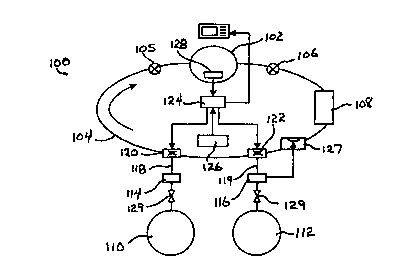
In FIG. 4, the overall mechanical system of the design is depicted and
suitably
comprises a flow loop, generally indicated at 100, in turn comprising a
flexible,
2 5 volumetrically defined counterlung 102 from which a diver inhales and to
which a diver
exhales a breathing gas mixture through a suitable mouthpiece. The counterlung
102 is
coupled into the flow loop 100 by means of suitable low pressure hoses 104
which define the
gas flow path of the flow loop. Gas flow direction through the low pressure
hoses 104 are
controlled by first and second 1-way check valves 105 and 106 which are
disposed along the
3 0 low pressure hoses 104 and positioned so as to define the flow of
breathing gas into and out
of the counterlung 102. Maintaining the correct breathing gas flow direction
is important,
since a diver's exhaled breath contains quantities of carbon dioxide which
must be removed
from the exhaled gas volume before the remaining residual oxygen-containing
gas is
reintroduced to the gas flow and, thus, the counterlung 102. Carbon dioxide
(COZ) is
3 5 removed from the exhaled gas volume by a CO~ scrubber canister 108 which
is disposed in
gas flow in a direction defined as down-stream from the counterlung 102.
Operation of the 1-
way check valves 105 and 106 ensures that the exhaled gas volume leaves the
counterlung
through the appropriate low pressure hose which is coupled to the CO, scrubber
canister 108,
-16-
T.._._ _.._._.__ .. __
CA 02296338 2000-O1-18
W O 99/03524
1
PCT/US98/14697
rather than allowing cross flow between COz containing exhaled gas and an
incoming volume
of breathing gas from the gas source.
The construction and operation of the CO~ scrubber canister 108 is well
understood by
those having skill in the art and may comprise any one of a number of commonly
used COz
removal systems. Preferably, the CO~ scrubber canister 108 comprises a soda
lime cartridge
having about 3 to 5 hours of CO~ scrubbing capability. Breathing gas is
supplied to the flow
loop 100 by a breathing gas source suitably comprising first and second
cylinders, 110 and
112, respectively, capable of receiving and holding a volume of a compressed
breathing gas.
The first cylinder 110 comprises an oxygen or oxygen rich gas, preferably
oxygen (OZ) in its
pure form, while the second tank I 12 is filled with a volume of a compressed
diluent gas,
such as air, which as will be described in greater detail below, may be mixed
with oxygen
from the first tank 110 to thereby vary the partial pressure of oxygen
provided to the flow
loop of the rebreather system. Preferably , the diluent tank 112 contains a
volume of
compressed air which, as is generally understood by those having skill in the
art, contains a
specific fraction of oxygen (0.21 ) in the gaseous mix. Alternatively, the
diluent gas
contained within the diluent tank 112 may be any one of the number of inert
gasses which
have been conventionally determined as suitable for deep diving operations, or
a custom
2 0 mixture of such an inert gas with a specific fraction of oxygen.
The oxygen and diluent tanks, 110 and 112 respectively, are coupled to the
flow loop
100 through respective high pressure regulators 114 and 116 respectively. The
pressure
regulators 114 and 116 regulate and reduce the gas flows from the oxygen and
diluent tanks
to a lower, operating, pressure suitable for the low pressure hoses 104
comprising the
2 5 rebreather flow loop 100. Various pressure regulator designs are suitable
for use with the
rebreather system of the present invention, and might indeed be implemented as
moving
orifice-type pressure regulators, balanced flow-through piston-type, or the
like. A typical
implementation of the pressure regulators 1 I 4 and 116 reduces the gas
pressure of
compressed oxygen or compressed diluent gas within their respective storage
tanks 110 and
3 0 112, from their nominal, compressed, values to a lower pressure of about
ten atmospheres ( 10
atm). While described as reducing gas pressures from current tank pressure to
about ten atm,
it will be understood by those with skill in the art that the pressure
regulators 114 and 116
may be set to deliver low pressure gas at pressures quite different from 10
atm.
Low pressure regulated gas, whether oxygen or diluent, is coupled to the flow
loop
35 100 by means of low pressure hoses 118 and 119, each of which are connected
to introduce
oxygen or diluent gas from their source tanks to individual mass flow control
valves 120 and
122. Oxygen is introduced into the flow loop I 00 through mass flow control
valve 120,
while the diluent gas is introduced to the flow loop through mass flow control
valve 122.
-17-
CA 02296338 2000-O1-18
WO 99/03524 PCTNS98/14697
1
During normal operation of the rebreather, mass flow control valves 120 and
122 determine
the amount of oxygen and diluent, respectively, which is introduced to the
system in order to
maintain the partial pressure of the breathing gas within the specified range.
Prior to discussing the construction of mass flow control valves 120 and 122,
it is
necessary to return momentarily to the graph of flow rate as a function of
depth as depicted in
FIG. 5. Inspection of the flow rate values shown in FIG. 5, and analysis of
the data contained
in Table 1, shows that for the oxygen consumption extremes chosen, both oxygen
and diluent
flow rates are approximately linear with respect to depth. Indeed, analysis of
the data of
Table 1 indicates that diluent, or air, flow rates will increase with depth at
a rate of
approximately 0.07 SLM per foot. Likewise, oxygen flow rates will decrease
with depth at a
rate of approximately -.014 SLM per foot. Similar calculations can be
performed on the data
of Table 2 to give similar results, varying only in the numerical value
obtained for the rate of
flow rate change per foot of depth.
Thus, with oxygen and diluent (or air) flow rates exhibiting linear dependence
on
depth, it can be understood that mass flow control valves 120 and 122, in one
embodiment of
the invention, are implemented as a simple, mechanical flow control valve,
preferably a first
stage regulator that produces an intermediate pressure that is depth
dependent, coupled to
2 0 sonic orifice, which produces flow rates dependent solely on depth in
accordance with a rate
of change derived in accordance with the invention. Such a mechanical
construction is well
within the contemplation of those having skill in the art and indeed, can be
easily
implemented by making suitable modifications to any one of a number of
conventional first
stage regulators implemented in prior art closed or semi-closed rebreather
systems. While
2 5 the mechanical embodiment of the invention has the advantage of
simplicity, it is unable to
account for the descent rate terms given in Equation 7. This further increases
the probability
that the partial pressure of oxygen will exceed the specified maximum value
during descent.
There are number of solutions to this problem such as adding a rigid volume
between the
oxygen rich gas source and the counterlung (a particular embodiment of which
is disclosed in
3 0 U.S. Patent No. 4,454,878 to Morrison) or the addition of an
electronically controlled
solenoid valve coupled to a pressure transducer, either of which stops or
reduces the flow of
oxygen rich gas when the descent rate exceeds a specified value. For an
embodiment that
includes an oxygen sensor, the electronically controlled valve functions to
stop the flow of
the oxygen rich gas before the partial pressure of oxygen exceeds the maximum
specified
3 5 value.
In a further embodiment of a semi-closed circuit rebreather system in
accordance with
the invention, mass flow control valves 120 and 122 suitably comprise
electronically
controlled mass flow valves operable in response to a control signal received
from a suitable
-18-
_. ~___._~~~._..._. .._._ _~._...._ . _. .
CA 02296338 2000-O1-18
WO 99/03524 PCT/US98/14697
1
signal processing circuit, thereby automating the control of gas flow from the
oxygen and
diluent tanks 110 and 112 respectively. The signal processing circuit 124 is
implemented, in
accordance with the invention, as a microprocessor, microcontroller, or a
digital signal
processor circuit, capable of being programed by a user with the various user
defined
parameters (such as oxygen consumption, the oxygen content of the oxygen and
diluent gas
cylinders, and the like), and further capable of carrying out the calculations
defined in
Equation 7 so as to define the flow rates from the oxygen and the diluent
cylinders as a
function of depth.
In this regard, the signal processing circuit 124 includes a sensor input port
for
receiving signals from a pressure transducer 126 which converts, in
conventional fashion, a
measurement of ambient pressure to a depth below the surface. Both the signal
processing
circuit i 24 and the pressure transducer 126 are implemented from
conventional,
commercially available components; the signal processing circuit 124 being
adapted from
any available firmware programmable microcontroller circuit having an input
and an output
bus and including an arithmetic computational ability. Various such circuits
are
manufactured by Motorola, Intel Corporation, and Advanced Micro Devices, all
of which are
suitable for incorporation into the present invention. The depth transducer
126 is likewise
implemented from a conventional, commercially available device and is offered
in various
forms as part of a dive computer suite, by virtually every recreational dive
equipment
manufacturer.
In operation, pressure transducer 126 senses the depth of a diver and provides
a
suitable control signal to signal processing circuit 124. In response, the
signal processing
2 5 circuit 124 calculates oxygen and diluent tank flow rates in accordance
with Equation 7,
using the value of depth determined by the pressure transducer 126, the
minimum and
maximum oxygen partial pressure values, the minimum oxygen consumption values
and
oxygen fraction values for the system which have been previously input by a
user.
In accordance with the invention, signal processing circuit 124 issues control
signals
to mass flow control valves 120 and 122, which adjust the oxygen and diluent
flow rates,
respectively, in response thereto.
In a preferred embodiment that includes both mechanical and electronically
controlled
mass flow valves, the electronically controlled valves are designed and
constructed to fail-
open. This condition will ensure that in the event of system failure, oxygen
is always
3 5 available to the diver in sufficient quantities to prevent hypoxia, while
the diver makes his
way to the surface in an emergency ascent.
In a further embodiment of the invention, it will be understood that the high
pressure
regulator 116 connected to the diluent source 112, may include an additional
low-pressure
-19-
CA 02296338 2000-O1-18
WO 99/03524 PCT/US98/14697
1
port to which a conventional SCUBA-type second stage regulator I27 may be
attached.
When the diluent source 112 is configured as a compressed air cylinder, the
compressed air
cylinder in combination with a second stage regulator functions as a bail-out
bottle under
certain emergency conditions. In the limit, the diluent cylinder 112, high
pressure regulator
116 and an optional second stage regulator 127 comprises a simple SCUBA-type
apparatus
such as depicted in FIG. 1.
Additionally, it will be understood by those having skill in the art that
using air as a
diluent gas source has certain disadvantages as the diving depth reaches and
exceeds 150
feet. In particular, the major component of air is nitrogen, which is
recognized as the
contributor to certain desirable physiological effects. Nitrogen narcosis is
known to effect
divers when the diving depth exceeds 1 SO feet and can lead to serious
consequences,
including death, due to its induced state of euphoria. Accordingly, the
invention may be
provided with a second diluent gas source filled with for example, a heliox
mixture (20%
oxygen and 79% helium) which is switched into the flow loop in place of air or
some other
oxygen/nitrogen mixture, at depths greater than about 150 feet. It will thus
be seen that the
rebreather system, in accordance with the invention, is adaptable to mixed-gas
diving, by
merely providing conventionally derived gas sources and performing the
necessary
2 0 calculations in accordance with the algorithm.
CLOSED CIRCUIT EMBODIMENT
In the semi-closed circuit embodiment described above, a major feature of the
invention is the dynamic and adaptable adjustment of oxygen and diluent flow
rates as a
2 5 function of depth alone. An accurate oxygen sensor provided in accordance
with the present
invention improves the performance of a rebreather system significantly. As
was depicted in
FIGS. 5 and 6 and in accordance with the values listed in Tables 1 and 2, when
the range of
oxygen consumption is bounded by a more restrictive set of minima and maxima,
flow rates
from the oxygen and diluent tanks are dramatically reduced, particularly for
the diluent tank.
3 0 Indeed, conventional closed circuit rebreather systems monitor the partial
pressure of oxygen
within the counterlung and provide additional oxygen to the system solely at a
rate necessary
to maintain a pre-set PO, value, i.e., 1.6 atmospheres. Conventional air or
diluent tanks are
provided to add gas during descent when the counterlung is collapsed by the
increase in
hydrostatic pressure. Conventional closed circuit rebreather systems are
designed to add
3 5 oxygen to the system at a rate equal to the rate oxygen is being consumed
by the diver.
However, conventional systems have no way of obtaining a direct measurement of
the
oxygen consumption rate and use an oxygen sensor primarily to monitor the PO,
within the
-20-
_ __.__ ~._____ W _ ._ . ... _.. ..T._._... ._ . . .. _
CA 02296338 2000-O1-18
WO 99/03524
1
PCT/US98/14697
counterlung. Gas flow control is adjusted to maintain POz at a constant preset
value,
typically the maximum allowed by CNS toxicity limits.
In accordance with principles of the present invention, a closed circuit
rebreather
system when used in combination with an accurate and reliable oxygen sensor
allows the
calculation of a POz value, based on practical recreational factors such as
decompression
considerations and pulmonary toxicity limits, which value can be calculated to
give
maximum dive time and minimum decompression time.
In the absence of other considerations, dive time is ultimately controlled by
the
capacity of the breathing gas tank, i.e., the amount of breathing gas that is
available, while
POz is controlled by the CNS toxicity limit. An illustration of the dependence
of
performance on oxygen partial pressure of a closed circuit rebreather is
depicted in FIG. 8.
FIG. 8 is a graphical representation of dive time in minutes plotted as a
function of PO2, with
no-decompression (No D) times plotted at various depths for various values of
PO~. As can
be seen in FIG. 8, for the shallowest depth of 60 feet and for a POZ of 1.6,
the no- -
decompression time limit greatly exceeds by the time limit imposed by the
capacity of the
tank, and the dive will be terminated when tank capacity is exhausted. It is
evident from FIG.
8 that the POz for this particular dive could be reduced to a value of about
1.0 without
impacting the dive time, i.e., the dive time would still be tank capacity
limited.
For intermediate depths of about 80 feet, the no-decompression time limit
corresponds
to the tank capacity limit at a PO~ of 1.6. Setting the PO~ to a lower value
would, in this case,
cause the diver to either ascend to a shallower depth when the no-
decompression time at 80
feet expires (a common practice among recreational divers known as multilevel
diving) or
2 5 remaining at 80 feet and enter a decompression regime. In this particular
example, the choice
of POZ = 1.6 is optimal, and to reduce it would have degraded a diver's
options. However, as
can be seen from FIG. 8, for depths in excess of 80 feet, i.e., for a depth of
100 feet, the
maximum no-decompression time (for a PO~ = 1.6) is about 40 minutes with the
CNS
toxicity Limit on POZ restricting the diver's options with respect to
additional No D time.
3 0 Thus, it can be seen that for a depth of about 100 feet and a No D time of
about 40 minutes,
considerable tank capacity remains. In this particular case, a diver has the
choice of either
remaining at 100 feet and accepting a decompression obligation or ascending to
a shallower
depth in order to remain within a No D regime. If a diver chooses to accept
the
decompression obligation, the diver may stay at I 00 feet until the remaining
tank capacity is
3 5 used, with the constraint that sufficient capacity must remain to pass
through the
decompression regime. For the No D multilevel dive, POz could have been
reduced to a
lower value such that the remaining tank capacity and No D times were equal
without
-21-
CA 02296338 2000-O1-18
WO 99/03524 PCT/US98/14697
1
diminishing dive time, but in the absence of pulmonary oxygen toxicity
considerations, this is
not necessary.
However, the addition of constraints associated with pulmonary oxygen toxicity
results in situations in which a reduced value of PO, improves the performance
of the
rebreather in several important aspects.
Turning now to FIG. 9, pulmonary toxicity limits, as defined by the National
Oceanographic and Atmospheric Administration (NOAA) have been superposed on
the
graphical representation of dive time and PO, of FIG. 8. As can be seen in
FIG. 9,
pulmonary oxygen toxicity considerations have the effect of decreasing
allowable dive time
as POZ increases. Thus, for depth shallower than approximately 60 feet there
are multiple
choices of the value of POz. One could choose a value of POZ where the
pulmonary toxicity
limit equals tank capacity (POZ = 1.0 in the illustration of FIG. 9), or
choose a lower value of
POZ where the no-decompression time equals tank capacity. Neither choice would
effect dive
time in this circumstance, but since there are well-defined daily pulmonary
constraints, the
small value of POZ is preferred. The dive time of any one particular dive is
not diminished,
but the pulmonary toxicity limits imposed by subsequent repetitive dives will
be increased.
Thus, it can be seen that where the pulmonary toxicity limit equals or exceeds
the dive
2 0 time as controlled by tank capacity, the optimum solution for POz is that
which equates no-
decompression time to tank capacity time.
For depths greater than 60 feet, i.e., depths at which pulmonary toxicity
limits restrict
dive times to values less than tank capacity, an additional degree of freedom
is available over
that imposed by conventional rebreather systems. Following the example of FIG.
6, for a
2 5 depth of approximately 100 feet, as was the case in the absence of
pulmonary toxicity limits,
a diver has a choice of either staying at that depth his No D limit and
accepting a
decompression obligation, or a diver may ascend to a shallower depth and stay
within the No
D limits. If a diver chooses the second option, i.e., a mufti level dive, both
capacity and no-
decompression times will be reduced somewhat. However, an optimum solution for
PO~ will
30 be either when the no-decompression time is equal to tank capacity time or
when the
pulmonary toxicity limit time is equal to tank capacity time and one can
anticipate either
eventuality by choosing the minimum of these values.
If a diver chooses to accept the decompression obligation, the diver may
remain at 100
feet, but it is important to note that if the pulmonary toxicity limit is
reached, the value of PO~
3 5 must be reduced to approximately 0.5 atm for which the pulmonary toxicity
time limit is
unlimited. However, POZ = 0.5 can result in an unnecessarily long
decompression. In order
to maximize bottom time while minimizing decompression time, a value of POz is
chosen
such that the tank capacity time at depth when diminished by the capacity
required for
-22-
_. _.. _ ~~.. .._~ _. _
CA 02296338 2000-O1-18
WO 99/03524 PCT/US98/14697
1
decompression, is equal to the pulmonary toxicity limit time at depth, that
has been
diminished by the pulmonary time required for maximum POZ during
decompression.
The above-described rules may be summarized with reference to the exemplary
simplified flow chart of FIG. 10 which illustrates the procedure. In
particular, in accordance
with the flow diagram of FIG. 10, the procedure begins by calculating the tank
capacity
limited dive time, including any time limitations imposed by a decompression
obligation. A
second calculation is performed and determines the dive time that is limited
by the no-
decompression time available for the desired diving depth. A further
calculation is
performed and determines the dive time that is limited by both single dive and
daily
allowable oxygen toxicity limits, with the minimum values used to govern the
dive. Care
must be taken to account for oxygen toxicity limitations imposed during any
decompression
obligation.
From the capacity limited dive time and the no-decompression limited dive time
values, a value of PO~ is determined from, for example, the graph of FIG. 8 or
FIG. 9, for
which the tank capacity limitation is equal to the no-decompression
limitation. Further, a
value of PO~ is determined for which the capacity limited dive time is equal
to the pulmonary
toxicity limited dive time as determined above. For either value of POz
determined above,
2 0 the minimum of these values is chosen as the PO~ set point for a closed
circuit rebreather
system constructed in accordance with practice of the present invention. The
value of POz is
set equal to the minimum of either value determined above, with the additional
constraint that
it be greater than 0.5 and less than the maximum allowable, i.e., 1.6 atm.
It is important to note that both single and daily allowable oxygen toxicity
limits be
2 5 monitored, with the minimum values used to govern the parameters of a
dive.
This method of calculating a particular value of PO, may be better understood
when
considered in the context of a specific example. As a practical matter, oxygen
toxicity dive
time limits are set out as a function of the partial pressure of oxygen in the
following table,
Table 3.
35
-23-
CA 02296338 2000-O1-18
1
WO 99/03524 PCT/US98/14697
TABLE 3
Po Single Dive Daily Limit
0.5 no limit no limit
0.6 720 min 720 min
0.7 570 570
0.8 450 450
0.9 360 360
1.0 300 300
1.1 240 270
1.2 210 240
1.3 180 210
1.4 150 180
1.5 120 180
i .6 45 150
Allowable dive times at a particular PO~ are converted into a rate of
accumulation of
what will be termed herein Oxygen Toxicity Units (OTU). For purposes of the
example, 300
is arbitrarily selected as the number of non-dimensional oxygen toxicity units
allowable.
Accordingly, for both single and daily oxygen toxicity limit calculation
purposes, the oxygen
2 5 toxicity unit accumulation rate or OTUR, can be established by simply
dividing 300 by the
allowable time. Thus, at an oxygen partial pressure of 1.0, OTUR can be
established by
simply dividing 300 by the allowable time. Thus, at an oxygen partial pressure
of 1.0, OTUR
is one unit per minute. In accordance with the invention, each value of PO, is
associates with
a corresponding OTU accumulation rate such that OTUR = OTUR (POZ). As a dive
3 0 progresses, allowable OTU will decrease, and if the dive enters a
decompression regime, the
OTU accumulation rate will increase as the necessary OTU's required for a
minimum
decompression time are set aside. The pulmonary time limit, ToTU, of the dive
may be
expressed as:
EQUATION 15
TOZ,U=IOT UREMAINING ~T UoEC~~ ~T URlPo2'
-24-
..._.. _....__.~__ ._ .... .........~_~.__._.._- ~_._ .._. . T ..... ..
___....._._
CA 02296338 2000-O1-18
1
WO 99/03524 PCT/US98/14697
where OTU~,~,N,NC represents oxygen toxicity units still available to a diver,
OTUpEc
represents the oxygen toxicity units set aside for any decompression regime
and OTUR (POZ)
represents the oxygen toxicity unit accumulation rate at a particular chosen
value of POZ.
The capacity limited, TcAn, which must also allow for gas consumption during
decompression, may be expressed in pertinent part as:
EQUATION 16
T CAP vCAPl O2
where V~~P 1S the remaining volumetric capacity of the oxygen tank as
indicated by tank
pressure, and OZ is the volumetric flow rate which for a closed circuit system
is equal to the
rate of oxygen consumption. One possible value of PO, for a particular dive is
obtained
when the pulmonary time limit ToT~ is equated to the capacity limited time,
TcA,,, or:
EQUATION I7
OT U~PQ2~=f OT UR~AINING OT UDECJ/(VCAPl O2~
for which there is unique solution for POz.
The second candidate for the choice of PO~ is achieved by equating the no
decompression time to the capacity limited time. No D times can be calculated
using a
2 5 number of different theories, the most common of which are based on the
work of John Scott
Haldane (1908). This theory models the human body as though it consisted of a
number
(typically between 5 and 12) of tissues, each having a different time scale
and allowable
nitrogen tension upon surfacing. This theory can be expressed by the following
differential
equation:
EQUATION 18
dNi/dt= (D-Ni) /Ti
3 5 where D is the depth, N; is a measure of the nitrogen tension in units of
feet of sea water, i; is
the "halftime," in units of minutes, and the subscript (); refers to any one
of the tissues of the
model. Typical values of i; range from 5 to 480 minutes.
For gasses that have a variable oxygen content, the equivalent depth that must
be used
-25-
CA 02296338 2000-O1-18
WO 99/03524 PCT/US98/14697
1
for the calculations, commonly referred to as the Equivalent Air Depth, is a
function of both
depth and PO2, and
EQUATION 19
EAD = 3 3 [ ( PCB PoZ ) / ~ 7 9 - 1 ]
where EAD has units of feet of sea water, PAMB and POZ have units of
atmospheres. By way
of example, if D= 99 feet, and the gas were air, PAMg = 4, POZ= 0.84, and
EAD=D=99 feet.
However, if the gas were oxygen rich, e.g., PO, = 1.4, EAD=76 feet., which
would result in
an increased NoD time. The formula for remaining NoD time is
EQUATION 20
NoD = Minimum { z iLn [ ( EAD-N1 ) / ( EAD - NCi ) ] }
where Ln is the natural logarithm, i.e., Ln(2)=0.693.
Thus at any time during the dive, the NoD time is a function of the previous
dive
profile as reflected in the present value of N, the depth as reflected in the
present value of
PpM~, and of course PO2
By equating this time to the capacity limited time, one can solve for the
second choice
of an optimum value of PO2.
2 5 EQUATION 21
NoD ( Po2 ) - T CAP
The optimum POZ is the minimum of the two choices found by solving Equations
16
and 21.
When any N>NC, decompression is required and Equation 20 may be used to
calculate
decompression times by simply replacing the minimum with the maximum of the
expression
indicated.
In practical terms, if the solution is found to be less than 0.5, value of POZ
is set equal
3 5 to 0.5 because lower values of POZ contribute no additional oxygen
toxicity units, and all
other factors being equal, a higher value of POz is preferable. On the other
hand if both
choices exceed 1.6, 1.6 is chosen in order to avoid CNS oxygen toxicity. These
PO, values
are, of course, calculated in situ by a suitable signal processing circuit
operating on data
-26-
T._ _ __._. _ . _
CA 02296338 2000-O1-18
WO 99/03524 PCT/US98/14697
1
provided by an oxygen sensor, an ambient pressure (depth) guage, a tank
capacity indicator
(pressure guage), and firmware pro~,nammable NoD and oxygen toxicity
accumulation
schedules, as bounded by the upper and lower limits of POZ as mentioned
previously. In situ
calculations provide for real-time adaptability of oxygen partial pressures
with respect to the
dynamic nature of a typical dive. In particular, the effects of a constantly
changing depth can
be taken into account in accordance with the invention, with suitable PO,
values being
constantly recalculated and dynamically provided to the diver. Thus, at any
point during a
dive the POZ value being delivered to a diver is optimized so as to maximize
bottom time
while accounting for any required decompression and the accumulation of oxygen
toxicity
units.
In summary, although certain embodiments of the invention, i.e., a semi-closed
circuit
rebreather system, do not require an oxygen sensor, certain performance
benefits may be
obtained by embodiments of the invention that include such an oxygen sensor.
Performance
enhancements are obtained by taking into account the reduced nitrogen content
of the
breathing mixture and the advantageous effect this has on no-decompression
times of a dive.
In addition, an oxygen sensor can be used to establish a more restrictive
range of oxygen
consumption for a particular diver, which results in substantially reduced
flow rates, longer
2 0 dive times and thus, greater efficiency.
Moreover, the closed circuit embodiment of the present invention functions in
terms of
a calculated discrete value of oxygen partial pressure. However, an
alternative design is able
to use the same rules developed for the semi-closed circuit embodiment but
with the limits on
2 5 oxygen partial pressure greatly reduced and centered about the value
calculated in accordance
with the closed circuit algorithm and the limits on oxygen consumption
substantially reduced
and centered about the value calculated by an oxygen sensor. While the semi-
closed circuit
rebreather system exhibits a capacity decrease as PO, increases, thus leading
to a more
sensitive dependence of dive time on PO2, the rules developed for
deternzination of POz for
3 0 the closed circuit rebreather remain applicable for the semi-closed
circuit system.
A particular embodiment of a closed circuit rebreather system, capable of
operation in
accordance with principles of the invention described above, is depicted in
FIG. 11. The
components of the closed circuit rebreather system of FIG. 11 are
substantially the same as
the components of the semi-closed circuit rebreather system, in accordance
with the
3 5 invention, as depicted in FIG. 4, but with the addition of a tank pressure
indicator 129
coupled to the supply tank and an oxygen sensor 128 provided within the
counterlung 102.
The oxygen sensor 128 and pressure indicator 129 are electronically coupled to
the signal
processing circuit 124 and provide the signal processing circuit with
information relating to
-27-
CA 02296338 2000-O1-18
WO 99/03524 PCT/US98/14697
1
the partial pressure of oxygen comprising the gas within the counter lung and
a figure of
merit corresponding to the remaining capacity of the tank. It is, of course,
axiomatic that the
signal processing circuit 124 be one of a type capable of performing the
calculations in
accordance with the algorithm of the present invention, so as to develop and
maintain a
suitable oxygen partial pressure and deliver breathing gas comprising that
optimal partial
pressure to the diver through the counterlung.
Oxygen sensor 128, like the signal processing circuit 124 and pressure
transducer 126,
is implemented as any one of a number of conventional, commercial available
oxygen
sensors, as would be understood by one having skill in the art. Various oxygen
sensor
designs are prevalent throughout the field and are a mandatory component to
the functioning
of conventional closed circuit rebreather systems.
Reliable closed and semi-closed rebreather systems have been disclosed which
operate
in accordance with an algorithm to adaptively control oxygen and diluent gas
flow rates as a
function of depth, so as to maximize a diver's bottom time while taking
deleterious
physiological effects into account. The embodiments described above, diving
depth, as
defined by ambient pressure, has been used as the primary determinant of gas
flow rates, with
relatively wide extremes of oxygen consumption rates setting boundary
conditions upon flow
2 0 rate calculations. As will be evident to those having skill in the art,
arbitrarily determined
boundary conditions can be significantly scaled down by monitoring and
recording a
particular diver's oxygen consumption profile for example, the resulting
extremes of which
may be substituted into the algorithm of the invention in order to further
refine the flow rate
calculations and further increase bottom time.
2 5 It will be recognized by those skilled in the art that various
modifications may be made
to the various preferred and other embodiments of the invention described
above, without
departing from the broad inventive scope thereof. It will be understood,
therefore, that the
invention is not limited to the particular embodiments, arrangement or steps
disclosed, is
rather intended to cover any changes, adaptations or modifications which are
within the scope
30 and spirit of the invention as defined by the appended claims.
-28-
__...-...~.._. _ ... . T_ _....___. __