Language selection

Search

Patent 2296441 Summary

Third-party information liability

Some of the information on this Web page has been provided by external sources. The Government of Canada is not responsible for the accuracy, reliability or currency of the information supplied by external sources. Users wishing to rely upon this information should consult directly with the source of the information. Content provided by external sources is not subject to official languages, privacy and accessibility requirements.

Claims and Abstract availability

Any discrepancies in the text and image of the Claims and Abstract are due to differing posting times. Text of the Claims and Abstract are posted:

  • At the time the application is open to public inspection;
  • At the time of issue of the patent (grant).
(12) Patent: (11) CA 2296441
(54) English Title: ONE PIECE MOLDED COMPONENT HIGH MOUNTED STOP LAMP
(54) French Title: FEU D'ARRET MONOBLOC A FIXATION HAUTE
Status: Expired and beyond the Period of Reversal
Bibliographic Data
(51) International Patent Classification (IPC):
  • B60Q 01/44 (2006.01)
  • B60Q 01/30 (2006.01)
  • F21S 43/00 (2018.01)
  • F21S 43/20 (2018.01)
  • F21S 43/40 (2018.01)
(72) Inventors :
  • BLOOMFIELD, RICHARD M. (United States of America)
  • DESAI, DEVAL M. (United States of America)
  • WHEAT, RONALD A. (United States of America)
(73) Owners :
  • NORTH AMERICAN LIGHTING, INC.
(71) Applicants :
  • NORTH AMERICAN LIGHTING, INC. (United States of America)
(74) Agent: SMART & BIGGAR LP
(74) Associate agent:
(45) Issued: 2004-08-24
(22) Filed Date: 2000-01-19
(41) Open to Public Inspection: 2000-12-23
Examination requested: 2000-01-19
Availability of licence: N/A
Dedicated to the Public: N/A
(25) Language of filing: English

Patent Cooperation Treaty (PCT): No

(30) Application Priority Data:
Application No. Country/Territory Date
09/339,078 (United States of America) 1999-06-23

Abstracts

English Abstract


A one piece molded vehicle lamp includes a housing portion, a lens portion,
and a
hinge connecting the housing portion to the lens portion. At least one
connector
secures the lens portion to the housing portion. A bulb is located on an
inside of the
housing portion. Light emanating from the bulb reflects light from the bulb
outward
through the lens portion.


Claims

Note: Claims are shown in the official language in which they were submitted.

CLAIMS:
1. A one piece molded vehicle lamp comprising:
a housing portion;
a lens portion;
a hinge connecting said housing portion to said lens portion;
at least one connector used to secure said lens portion to said housing
portion; and
a bulb located on an inside of said housing portion;
wherein light emanating from said bulb reflects light from the bulb outward
through the lens portion.
2. A one piece molded vehicle lamp as claimed in claim 1 wherein the
housing portion is formed from a transparent plastic material.
3. A one piece molded vehicle lamp as claimed in claim 2 wherein said
transparent plastic material is lightweight.
4. A one piece molded vehicle lamp as claimed in any of claims 1-3 further
comprising a reflective finish provided on said inside of said housing
portion.
5. A one piece molded vehicle lamp as claimed in any of claims 1-4 wherein
the at least one connector is provided on said lens portion.

6. A one piece molded vehicle lamp as claimed in any of claims 1-5 wherein
said housing portion includes an opening for allowing bulb members to be
affixed
on said inside of said housing portion.
7. A one piece molded vehicle lamp as claimed in any of claims 1-6 wherein
said vehicle lamp is a vehicle stop lamp.
8. A one piece molded vehicle lamp as claimed in any of claims 1-7 further
comprising a mounting means for mounting said vehicle lamp on a vehicle.
9. A molded high mounted stop lamp comprising:
a housing portion having a parabolic shaped interior;
a bulb mounted in said interior;
a reflective finish applied directly to the housing portion;
a lens portion; and
a living hinge connecting said housing portion to said lens portion;
such that said reflective finish reflects light from said bulb through said
lens
portion.
10. A molded high mounted stop lamp as claimed in claim 9 further comprising:
mounting tabs extending from a first side and from a second side of said
housing portion, such that the housing portion may be rigidly affixed to a
vehicle.

11. A molded high mounted stop lamp as claimed in any of claims 9-10 further
comprising:
a snap means provided on an inside edge of said lens portion for inserting
said snap means into a corresponding hole on said housing portion.
12. A molded high mounted stop lamp as claimed in any of claims 9-11
wherein said housing portion includes at least one cavity for mounting said
bulb.
13. A molded high mounted stop lamp as claimed in any of claims 9-12
wherein said housing portion is a lightweight, transparent material.
14. A molded high mounted stop lamp as claimed in any of claims 9-13
wherein the housing portion is a rectangular-like structure.

Description

Note: Descriptions are shown in the official language in which they were submitted.


CA 02296441 2000-O1-19
ONE PIECE MOLDED COMPONENT HIGH MOUNTED STOP LAMP
FIELD OF INVENTION
This invention relates to the field of automobile lamp assemblies, and in
particular, to a one-piece molded high mounted stop lamp assembly.
BACKGROUND OF THE INVENTION
High mounted stop lamps ("HMSL") have been a requirement in this country
for several years. Automobile manufacturers have provided various types of
lamp
assemblies to meet this requirement.
A conventional high mounted stop lamp consists of a housing with a reflective
coating on the inside and a lens mounted thereto with a bulb inside. While
this type
of lamp assembly may come in various shapes and sizes, many of these
assemblies
require several components to be connected together, including in addition to
the lens
and housing, a separate bracket to facilitate the attachment of the bulb
socket. A
disadvantage of these structures is the high tooling and lamp costs, as well
as the
difficulty of assembly and the length of manufacturing time. Other indirect
consequences of these designs include high left-over scrap and added vehicle
weight.
1

CA 02296441 2000-O1-19
SUMMARY OF THE INVENTION
In one aspect of the present invention, a one piece molded vehicle lamp
includes a a housing portion, a lens portion, and a hinge connecting the
housing
portion to said lens portion. At least one connector is used to secure the
lens portion
to the housing portion. A bulb is located on an inside of the housing portion,
wherein
light emanating from the bulb reflects light from the bulb outward through the
lens
portion.
In another aspect of the present invention, a molded high mounted stop lamp
includes a housing portion having a parabolic shaped interior. The stop lamp
also
includes a bulb is mounted in the interior, a reflective finish, and a lens
portion. A
living hinge connects the housing portion to the lens portion, such that the
reflective
finish reflects light from the bulb through the lens portion.
2

CA 02296441 2000-O1-19
DETAILED DESCRIPTION OF PREFERRED EMBODIMENTS
The present invention represents an improvement over prior high mounted
stop lamps in that it is constructed from a one piece body molded from a
plastic
material. The one piece body is formed from a transparent plastic material and
comprises a housing portion with a reflective finish and a lens portion. The
body is
folded along a living hinge, connecting the lens portion like a lid to the
housing
portion, forming a box-like structure.
Preferably, the body is molded out of a transparent plastic material. In this
manner, the lens portion of the body is pre-made to allow light from a bulb
located
inside the housing portion to emanate therethrough. The reflective finish is
applied
directly to the housing portion of the body, preferably on the inside surface
thereof,
but not the lens portion. In this manner, in use, the interior surface of the
housing can
reflect light from the bulb outward through the transparent lens portion.
The one piece body may also be molded with additional components. For
example, means for securing that unsecured end of the lens portion to the
housing
portion can be provided, i.e., the lens portion can be molded with a snap
member and
housing portion can be molded with a corresponding hole in which the snap
member
can be inserted. In this manner, after the body is molded and the finish is
applied, the
lens portion is simply folded over along the living hinge and snapped to the
housing
portion.
Also, one or more openings can be molded in the housing portion to allow
bulb members to be inserted and attached therein. Mounting tabs may also be
molded
on the exterior of the housing portion which can be used to mount the body to
the
automobile. The body may also be molded in virtually any shape, including
having a
3

CA 02296441 2000-O1-19
portion of the housing behind the light source in the shape of a parabola, for
reflecting
and directing the light outward through the lens portion.
The present invention makes manufacturing and assembly easy and lower in
cost in relation to prior devices. Once the body is molded and the reflective
finish is
applied to the housing portion, the lens portion is simply folded toward the
housing
portion and snapped together. The steps needed to install a separate lens onto
the
housing and secure other components thereto are substantially eliminated.
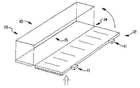
Figures 1 and 2 show two embodiments of the present invention. Figure 1
shows a body 10 in the shape of a rectangular box with a housing portion 13
and lens
portion 12 connected by a living hinge 14, wherein two separate connectors 11
are
used to secure the lens portion 12 of the box to the housing portion 13. A
reflective
finish 15 is provided on the inside of the housing portion 13.
Figure 2 shows an embodiment having a body 1 with a housing portion 2 and
lens portion 6, wherein the back surface of the housing portion 2 is in the
shape of two
parabolas. This shape makes for efficient reflection of light emanating from
the bulb
4 outward through the lens portion 6. Mounting tabs 5 extend from either side
of the
body for mounting the body to the automobile. A single snap 8 is provided on
the
inside edge of the lens portion 6 which can be inserted into a corresponding
hole 9
molded in place on the housing portion 2. It should be understood that the
reverse
construction can be used as well. Line AA represents the axis of the living
hinge
which separates the housing portion 2 from the lens portion 6. Holes 3 are
provided
for bulbs 4. A reflective finish 7 is provided on the inside of the housing
portion 2,
but not on the lens portion 6.
4

Representative Drawing
A single figure which represents the drawing illustrating the invention.
Administrative Status

2024-08-01:As part of the Next Generation Patents (NGP) transition, the Canadian Patents Database (CPD) now contains a more detailed Event History, which replicates the Event Log of our new back-office solution.

Please note that "Inactive:" events refers to events no longer in use in our new back-office solution.

For a clearer understanding of the status of the application/patent presented on this page, the site Disclaimer , as well as the definitions for Patent , Event History , Maintenance Fee  and Payment History  should be consulted.

Event History

Description Date
Inactive: IPC deactivated 2021-10-09
Inactive: First IPC assigned 2019-08-20
Inactive: IPC assigned 2019-08-07
Inactive: IPC expired 2018-01-01
Time Limit for Reversal Expired 2009-01-19
Letter Sent 2008-01-21
Inactive: IPC from MCD 2006-03-12
Grant by Issuance 2004-08-24
Inactive: Cover page published 2004-08-23
Pre-grant 2004-06-09
Inactive: Final fee received 2004-06-09
Notice of Allowance is Issued 2003-12-12
Letter Sent 2003-12-12
Inactive: Approved for allowance (AFA) 2003-12-02
Amendment Received - Voluntary Amendment 2003-10-17
Inactive: S.30(2) Rules - Examiner requisition 2003-04-17
Application Published (Open to Public Inspection) 2000-12-23
Inactive: Cover page published 2000-12-22
Letter Sent 2000-04-19
Inactive: Single transfer 2000-03-27
Inactive: First IPC assigned 2000-03-16
Inactive: IPC assigned 2000-03-08
Inactive: Courtesy letter - Evidence 2000-03-07
Inactive: Filing certificate - RFE (English) 2000-03-03
Inactive: Inventor deleted 2000-03-01
Application Received - Regular National 2000-02-18
Request for Examination Requirements Determined Compliant 2000-01-19
All Requirements for Examination Determined Compliant 2000-01-19

Abandonment History

There is no abandonment history.

Maintenance Fee

The last payment was received on 2004-01-19

Note : If the full payment has not been received on or before the date indicated, a further fee may be required which may be one of the following

  • the reinstatement fee;
  • the late payment fee; or
  • additional fee to reverse deemed expiry.

Patent fees are adjusted on the 1st of January every year. The amounts above are the current amounts if received by December 31 of the current year.
Please refer to the CIPO Patent Fees web page to see all current fee amounts.

Fee History

Fee Type Anniversary Year Due Date Paid Date
Application fee - standard 2000-01-19
Request for examination - standard 2000-01-19
Registration of a document 2000-01-27
MF (application, 2nd anniv.) - standard 02 2002-01-21 2002-01-11
MF (application, 3rd anniv.) - standard 03 2003-01-20 2003-01-06
MF (application, 4th anniv.) - standard 04 2004-01-19 2004-01-19
Final fee - standard 2004-06-09
MF (patent, 5th anniv.) - standard 2005-01-19 2005-01-06
MF (patent, 6th anniv.) - standard 2006-01-19 2006-01-05
MF (patent, 7th anniv.) - standard 2007-01-19 2007-01-02
Owners on Record

Note: Records showing the ownership history in alphabetical order.

Current Owners on Record
NORTH AMERICAN LIGHTING, INC.
Past Owners on Record
DEVAL M. DESAI
RICHARD M. BLOOMFIELD
RONALD A. WHEAT
Past Owners that do not appear in the "Owners on Record" listing will appear in other documentation within the application.
Documents

To view selected files, please enter reCAPTCHA code :


To view images, click a link in the Document Description column. To download the documents, select one or more checkboxes in the first column and then click the "Download Selected in PDF format (Zip Archive)" or the "Download Selected as Single PDF" button.

List of published and non-published patent-specific documents on the CPD .

If you have any difficulty accessing content, you can call the Client Service Centre at 1-866-997-1936 or send them an e-mail at CIPO Client Service Centre.


Document
Description 
Date
(yyyy-mm-dd) 
Number of pages   Size of Image (KB) 
Representative drawing 2000-12-07 1 6
Drawings 2003-10-16 1 33
Claims 2003-10-16 3 67
Abstract 2000-01-18 1 10
Description 2000-01-18 4 133
Claims 2000-01-18 3 61
Drawings 2000-01-18 2 27
Representative drawing 2004-07-19 1 9
Filing Certificate (English) 2000-03-02 1 164
Courtesy - Certificate of registration (related document(s)) 2000-04-18 1 113
Reminder of maintenance fee due 2001-09-19 1 116
Commissioner's Notice - Application Found Allowable 2003-12-11 1 160
Maintenance Fee Notice 2008-03-02 1 174
Correspondence 2000-03-01 1 12
Correspondence 2004-06-08 1 33