Note: Descriptions are shown in the official language in which they were submitted.
CA 02296472 2000-O1-20
DEVICE FOR DETECTING POSITION
FIELD OF THE INVENTION
The invention relates to an apparatus for detecting the
position of an object which can move along a predefined path. Such
apparatus may be used for controlling the position of a lift cage or the like
and thus ensuring its positioning at predetermined stops according to floor
levels.
BACKGROUND OF THE INVENTION
European patent 694 792 discloses an apparatus of this type for
detecting the position of a movable object, which has an acoustic signal
waveguide which extends along a travel path and has a predetermined,
uniform speed of propagation of sound, and has a signal input coupler, which
is connected to a signal generator and is located on the movable object, to
couple an acoustic signal into the acoustic signal waveguide. In this case,
signal output couplers are arranged at both ends of the acoustic signal
waveguide and are each connected to a counter, the two counters being
clocked by a clock generator and connected to a subtracter for the output
signals from the two counters. The output signal from the subtracter, as a
measure of the propagation-time difference of the acoustic signal coupled in
from the point at which it is coupled in to the signal output couplers, can be
processed by an evaluation unit to form a signal which is representative of
the instantaneous position of the movable object on the travel path, the
signal
input coupler operating with a signal spacing which is greater than the
propagation time of sound from one end of the travel path to the other. If the
movable object is at a standstill, standing waves can form, depending on the
position of the object, as the result of reflections of the acoustic signal at
the
CA 02296472 2004-11-22
-2-
ends of the acoustic signal waveguide, and can lead to measurement
problems as a result of fluctuations in amplitude.
SUMMARY OF THE INVENTION
It is an object of an aspect of the invention to provide an
apparatus for detecting the position of an object which can be moved
along a prescribed path, with which it is possible to pick up measured
values even when the object is at a standstill.
An apparatus for detecting the position of an object moveable
along a predetermined travel path in accordance with the present
invention comprises
an acoustic signal waveguide extending along the travel path and
having a predetermined, uniform speed of propagation of sound;
a signal input coupler located on the moveable object, to couple a
clocked acoustic signal into the acoustic signal waveguide,
at least one signal output coupler being arranged at one end of the
acoustic signal waveguide and being connected to an evaluation unit for
determining the propagation-time of the sound signal from a position at
which it is coupled in to the at least one signal output coupler and for
generating a signal representative of the instantaneous position of the
moveable object on the travel path,
wherein the signal input coupler couples in, as acoustic signal,
adjacent pulses having a varying time interval.
By varying the time intervals between successive pulses fed
into the acoustic signal waveguide, it is possible to pick up valid
measured values even in unfavourable stopping positions of the movable
object, since in this case the standing wave is shifted as the result of
variation of the repetition time, and thus evaluation outside the oscillation
nodes of the said wave is made possible.
CA 02296472 2000-O1-20
-3-
Further objects, embodiments and advantages of the
invention will become apparent from the following description and the
claims.
BRIEF DESCRIPTION OF THE DRAWINGS
The invention will be explained in more detail below with
reference to a preferred embodiment illustrated schematically in the
appended drawings.
Fig. 1 shows, schematically, an embodiment of an apparatus for
detecting position according to the invention.
Fig. 2 shows a timing diagram relating to the signals of the apparatus
from Fig. 1.
DETAILED DESCRIPTION OF THE PREFERRED EMBODIMENT
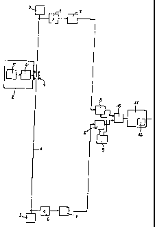
The apparatus shown for detecting position, which can be used in
particular for detecting the position of a lift cage, comprises a acoustic
signal
waveguide 1, for example a steel rail or in particular a wire, which extends
along a predefined travel path, along which a moveable object 2, for example
a lift cage, can be moved to and fro. The acoustic signal waveguide 1 having
a predetermined, uniform speed of propagation of sound, is clamped or held
in a damped manner at both ends in a damping clamp or mounting 3.
The moveable object 2 carries a signal input coupler 4 which is
connected to a signal generator 5, for example an oscillator, via a signal
matching circuit 4'. The signal input coupler 4, which in particular operates
inductively, couples an acoustic signal, which periodically includes a
synchronization pulses S received from the signal generator 5, into the
acoustic signal waveguide 1. The synchronization pulses S have a clock
period greater than the duration of the propagation of the acoustic signal
from
one end of the acoustic signal waveguide 1 to the other.
CA 02296472 2000-O1-20
-4-
In addition, the signal input coupler 4 couples in additional pulses
M, specifically a large number of additional pulses M, during each clock
period of the synchronization pulses S. The clock period of the additional
pulses M is such that a distance resolution, needed for example for braking
and for moving to an exact position of the object 2, is achieved in the
direction
of the travel path.
The synchronization pulses S are marked, that is to say can be
distinguished from the additional pulses M during the evaluation. The marking
can be made, for example, by their clock period being an appropriate multiple
of the clock period of the additional pulses M, and additionally by their
temporal offset in relation to the additional pulses M, for example by one
half
clock period, cf. the pulse train generated by the signal generator 5 in the
first
line of Fig. 2. Then, a predetermined number of m additional pulses M follows
a synchronization pulse S in each case.
However, marking can also be made in an other way, thus the
synchronization pulses S can be distinguished from the additional pulses M
by modulation, pulse width, pulse height or the like.
The synchronization and additional pulses S, M to be coupled in
may be short electromagnetic pulses, for example simple pulses or pulse
trains, or periodic frequency shift keying. The synchronization pulses S are
used when the travel path is very long, for example in lifts in multi-storey
buildings, in which case the necessary distance resolution leads to new
pulses being coupled into the acoustic signal waveguide 1 before a preceding
pulse has reached the end of the signal waveguide 1.
A signal output coupler 6 is arranged in each case at the ends of
the acoustic signal waveguide 1. This is preferably a piezoelectric signal
output coupler 6, however those operating inductively or capacitively can also
be used.
In order that the signal output coupler 6 can pick up an evaluable
signal even when the object 2 is at a standstill, and therefore the signal
generator 5 is in an unfavourable stopping position thereof, and does not
CA 02296472 2000-O1-20
-5-
operate in an oscillation node of a standing wave produced by reflection at
the end of the acoustic signal waveguide 1, the additional pulses M are
coupled in with a varying time interval, as emerges from the signal
illustrated
in Fig. 2 and fed into the acoustic signal waveguide 1. The time interval of
the
additional pulses M is expediently jittered by 0.1 ms, for example, around a
mean value of, for example, 1.0 ms. This variation can be carried out in a
predetermined sequence or else randomly, and preferably with a
predetermined variability around the mean value.
Each signal output coupler 6 is connected to a signal matching
circuit 7 whose output lines in each case lead to a counter 8. Both the
counters 8 are clocked by a clock generator 9, an oscillator. The clock time
of
the clock generator 9 is considerably lower than the propagation time of the
sound from one end of the acoustic signal waveguide 1 to the other and is
selected in accordance with the desired measurement path resolution. The
outputs from the counters 8 are fed to a subtracter 10, which forms the
difference of the output signals of the counters 8 and feeds it to an
evaluation
unit 11, for example a microprocessor, where the output signal from the
subtracter 10 is evaluated.
The synchronization pulses S are used to indicate to the
evaluation unit 11 which following pairs of additional pulses belong to each
other, namely the respective nth, that is to say the first, second, third and
so
on, additional pulses M arriving at the two signal output couplers 6
(designated by A and B in Fig. 2) at different times Ta and Tb following the
respective synchronization pulse S, in order that the evaluation unit 11 can
detect or determine the associated absolute time difference Ta - Tb = 0T
between associated additional pulses M, and hence the position of the object
2. The jittering of the additional pulses M has no influence on this, since
the
time difference is absolute.
The evaluation in order to detect the position is primarily carried
out in relation to the additional signals M, however the synchronization
pulses
S can also be evaluated in this regard, specifically above all but not
CA 02296472 2000-O1-20
-6-
exclusively when the respective mth additional pulse is specially marked, in
order in this way to serve as a synchronization pulse S.
If the movable object 2 is located in the centre between the signal
output couplers 6, the outputs from the counters 8 are equal and their
difference is zero. If the object 2 (in the case of a vertical path) is
located
above the centre, the output from the counter 8 which is connected to the
upper signal output coupler 6 is smaller than that of the other. From the
propagation time difference of the additional pulses M belonging together in
the acoustic signal waveguide 1, determined by the subtracter 10, and the
known sound speed in the latter, there results the distance of the movable
object 2 from the centre. Since the difference would have a different sign if
the movable object 2 were to be located below the centre, it is also known
whether the movable object 2 is located above or below the centre, that is to
say the exact position of the movable object 2 can thus be calculated. A
digital or analog position signal which can be generated by the evaluation
unit
11 can be used for tracking control.
A monitoring circuit 12 (watchdog) of the evaluation unit 11 can be
used for the simple monitoring of the measurement path in the case of an
input coupling which is constant over time of the input coupling signal. In
the
case of a contamination which is capable of damping the signal on the
acoustic signal waveguide 1, the difference determined by the subtracter 10
exceeds a predetermined value, to which the monitoring circuit 12 responds
in order to trigger a corresponding alarm signal or the like.
The speed of sound in a acoustic signal waveguide 1 made of
steel is approximately 5300 m/s. In the case of a time resolution of 188 ns,
for
which a clock generator frequency of 5.3 MHz is necessary, the location
resolution of the measurement path is about 1 mm.
Instead of being coupled to the signal generator 5, the signal input
coupler 4 may be triggered by evaluation unit 11 to couple the acoustic
signals into the signal waveguide 1. Instead it is also possible that the
signal input coupler 4 triggers the evaluation unit 11 via an electric signal
to
CA 02296472 2000-O1-20
-7-
define the temporal start of each coupling of an acoustic signal into the
signal waveguide 1 for the evaluation to be done by the evaluation unit 11.
Instead of the preferred provision of a signal output coupler 6
at each of the two ends of the signal waveguide 1, only one signal output
coupler 6 provided at one of the ends of the signal waveguide 1 may be
used.
While the invention has been shown and described with
reference to a preferred embodiment, it should be apparent to one of
ordinary skill in the art that many changes and modifications may be made
without departing from the spirit and scope of the invention as defined in
the claims.