Note: Descriptions are shown in the official language in which they were submitted.
CA 02296591 2000-O1-17
WO 99/10268 PCT/US98/15273
1
METHOD AND APPARATUS FOR
WINDING FIBER ON A SPOOL
BACKGROUND OF THE INVENTION
Field of the Invention
The present invention relates to a method and apparatus for winding a
continuous length of fiber onto a spool and, more particularly, to a method
and
apparatus for winding a continuous length of optical waveguide fiber onto
first
and second sections of a spool.
to Description of the Related Art
A manufacturer of optical waveguide fiber (optical fiber) typically must
dispense sections of optical fiber from a bulk spool, which contains a large
amount of optical fiber, onto respective shipping spools, which are sent to
customers. Both ends of the optical fiber on the shipping spool must be
readily
15 accessible for testing. Therefore, the manufacturer winds a first portion
of the
optical fiber onto a sample section of the shipping spool and winds the
remainder of the optical fiber onto a separate, main section of the shipping
spool. A conventional process for winding the optical fiber onto the sample
and main sections of the shipping spool involves both manual and automatic
2 o winding steps. Specifically, at a manual winding station, an operator
manually
pulls a portion (typically ten meters) of the optical fiber from the bulk
spool
through a hole in a flange of the shipping spool and manually winds it onto
the
CA 02296591 2000-O1-17
WO 99/10268 PCT/US98/15273
2
sample section of the shipping spool. The operator then transfers the shipping
spool from the manual winding station to a winding apparatus, which
automatically winds a desired amount of the optical fiber from the bulk spool
onto the main section of the shipping spool. The operator subsequently severs
the optical fiber extending between the shipping spool and the bulk spool.
The conventional process is time consuming and inefficient. For
example, the manual pulling and winding steps occupy the operator=s time,
and the operator cannot perform the steps quickly. Furthermore, the tension in
the manually-wound, optical fiber varies, and, if the operator winds the
optical
to fiber onto the sample section too tightly, the optical fiber must be
unwound and
rewound. The need to transfer the shipping spool from the manual winding
station to the winding apparatus further contributes to the time- consuming
and
inefficient nature of the conventional process.
Additionally, manual winding of the optical fiber on the sample section of
i5 the shipping spool may contribute significantly to injuries to the
operator.
Manual winding requires extension of the upper arm and continual rotation of
the lower arm around the elbow. During a typical 12 hour shift, the operator
will experience several hundred shoulder and elbow rotations per shift.
SUMMARY OF THE 1NVENT10N
2o An object of the present invention is to provide a substantially
automated winding method and apparatus.
Another object of the present invention is to provide a winding method
and apparatus that quickly wind optical fiber on a shipping spool.
Another object of the present invention is to provide a winding method
25 and apparatus that wind a continuous length of optical fiber onto a sample
section and a main section of a shipping spool such that both ends of the
optical fiber are readily accessible for testing.
Yet another object of the present invention is to provide a winding
method and apparatus that consistently provide a desired amount of tension in
3 o an optical fiber wound on a sample section of a shipping spool.
CA 02296591 2000-O1-17
WO 99/10268 PCTNS98/15273
3
Additional objects and advantages of the invention will become
apparent from the description which follows. Additional advantages may also
be learned by practice of the invention.
In a broad aspect the invention provides a method of winding a first
portion of a continuous length of fiber from a fiber supply onto an object.
The
method comprises the steps of preliminarily winding a first portion of the
continuous length of fiber to collect the first portion from the fiber supply
while
a second portion of the continuous length of fiber remains at the fiber supply
and winding the collected first portion onto the object while the second
portion
to remains at the fiber supply.
In another broad aspect, the invention provides an apparatus for
winding a first portion of a continuous length of fiber from a fiber supply
onto
an object. The apparatus comprises a reel that rotates to collect the first
portion of the continuous length of fiber while a second portion of the
i5 continuous length of fiber remains at the fiber supply and a carriage that
rotatably supports the reel and that causes the reel to revolve around the
object to wind the collected first portion of the continuous length of fiber
onto
the object while the second portion remains at the fiber supply.
In another broad aspect, the invention provides a method of winding a
2 o continuous length of fiber from a fiber supply onto first and second
sections of
a spool. The method comprises the steps of preliminarily winding a first
portion of the continuous length of fiber to collect the first portion from
the fiber
supply while a second portion of the continuous length of fiber remains at the
fiber supply, winding the collected first portion onto the first section of
the
25 spool while the second portion remains at the fiber supply, and winding the
second portion of the continuous length of fiber from the fiber supply onto
the
second section of the spool.
In another broad aspect, the invention provides an apparatus for
winding a continuous length of fiber from a fiber supply onto first and second
3 o sections of a spool. The apparatus comprises a first device that collects
a first
portion of the continuous length of fiber from the fiber supply and winds the
*rB
CA 02296591 2000-O1-17
WO 99/102b8 PCT/US98/15273
4
collected first portion onto the first section of the spool, and a second
device
that winds a second portion of the continuous length of fiber onto the second
section of the spool.
It is to be understood that both the foregoing summary and the following
detailed description are exemplary only and are not restrictive of the
invention,
as claimed.
BRIEF DESCRIPTION OF THE DRAWINGS
The invention will be described in conjunction with the accompanying
drawings, which illustrate a presently preferred embodiment.
to FIG. 1 is a side view of a preferred embodiment of a winding apparatus
according to the present invention, showing a sample section winding device in
a winding position.
FIG. 2 is a side view of a portion of the winding apparatus of FIG. 1,
showing an optical fiber being wound onto a reel of the sample section winding
device.
FIG. 3 is a side view of a portion of the winding apparatus of FIG. 1,
showing the optical fiber being wound from the reel onto a sample section of a
spool.
FIG. 4 is a side view of a portion of the winding apparatus of FIG. 1,
2 o showing the optical fiber being wound onto a main section of the spool.
FIG. 5 is a side view of the winding apparatus of FIG. 1, showing the
sample section winding device in a retracted position.
FIG. 6 is a top view of the sample section winding device taken along
line 6-6 of FIG. 5.
FIG. 7 is a partial sectional view of the reel of the winding apparatus of
FIG. 1.
FIG. 8 is a sectional view of the spool, a shaft, and bolster plates of the
winding apparatus of FIG. 1.
DESCRIPTION OF THE PREFERRED EMBODIMENT
3o Reference will now be made in detail to the preferred embodiment
illustrated in the drawings.
CA 02296591 2000-O1-17
WO 99/10268 PCTNS98/15273
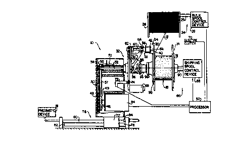
As shown generally in FIG. 1, a preferred winding apparatus 10 winds a
continuous length of optical fiber 12 onto a shipping spool 14. As shown in
FIG. 8, the shipping spool 14 has a sample (first) section 16 and a main
(second) section 18. The sample section 16 is recessed in a flange 20. The
5 flange 20 has a hole 22 that permits the continuous length of optical fiber
to
extend between the sample and main sections 16 and 18.
The winding apparatus 10 includes a fiber supply 24 that supplies the
continuous length of optical fiber, a sample section winding device (first
device) 32 that collects a minor or first portion of the continuous length of
to optical fiber from the fiber supply 24 and winds the collected first
portion onto
the sample section 16 of the shipping spool 14, and a main section winding
device (second device) 86 that winds a major or second portion of the
continuous length of optical fiber onto the main section 18 of the shipping
spool 14.
The fiber supply 24 preferably includes a bulk spool 26, which has
optical fiber wound thereon, and a bulk spool control device 28, which
controls
the rotation of the bulk spool 26 by controlling rotation of a shaft 29 upon
which
the bulk spool 26 is mounted. The fiber supply 24 may also include
conventional components (not shown), such as pulleys, that tension the optical
2o fiber and otherwise assist in the winding process. A processor 30
communicates with the bulk spool control device 28 to control the supply of
optical fiber by the fiber supply 24.
The sample section winding device 32 preferably includes a reel 34
having an elastic portion 36 with an angled slit 38, which extends
substantially
parallel to a rotational axis RA of the reel 34 and which is designed to grip
a
free end of the first portion of the continuous length of optical fiber (FIG.
7).
The reel 34 also has a flange 40 with a beveled edge 42. The beveled edge
42 prevents damage to the optical fiber if it should contact the flange 40
during
winding onto the reel 34.
3 o A motor 44, which is controlled by the processor 30, rotates the reel 34
about the axis RA (FIG. 1 ). A power train connecting the motor 44 to the reel
CA 02296591 2000-O1-17
WO 99/10268 PCT/US98/15273
34 includes a shaft 46 of the motor 44, a pulley 48 mounted on the shaft 46, a
belt 50, a rotatable main shaft 52 having pulleys 54 and 56 mounted on
opposite ends thereof, a belt 58, and a rotatable reel shaft 60 having a
pulley
62 mounted on an end thereof. The pulleys 48, 54, 56, and 62 are all fixed on
5 their respective shafts 46, 52, and 60 so that they do not rotate relative
to the
shafts.
A hysteresis slip clutch 64 (Magpower, part no. HCD1-1) connects the
reel shaft 60 and the reel 34. The slip clutch 64 causes the reel shaft 60 and
the reel 34 to be fixed together until a torque on the reel 34 exceeds an
i0 opposing torque on the reel shaft 60 by a predetermined amount. When the
predetermined amount is exceeded, the slip clutch 64 permits the reel shaft 60
and the reel 34 to rotate relative to one another. The slip clutch 64 can be
adjusted to provide a predetermined amount of torque. The significance of the
slip clutch 64 will be evident during the explanation of the operation of the
winding apparatus 10.
A carriage 66 supports the reel 34, along with a counterweight 68. The
motor 44 rotates the carriage 66 to cause the reel 34 and the counterweight 68
to revolve around an axis MA, which is also the rotational axis of the sample
and main sections 16 and 18 of the shipping spool 14. The reel 34 is
2 o preferably revolved around the axis MA in a direction that causes the
least
amount of bending of the optical fiber extending through the hole 22 in the
flange 20.
A power train connecting the motor 44 to the carriage 66 includes the
shaft 46, a pulley 49 mounted on the shaft 46, a belt 51, a hollow, first
clutch
shaft 53 having a pulley 55 and an electric clutch 70 mounted on opposite
ends thereof, a solid, second clutch shaft 57 having a pulley 59 mounted
thereon, a belt 61, and a pulley 63 mounted on the carriage 66. The pulleys
49, 55, 59, and 63 are all fixed to the component upon which they are mounted
so that they do not rotate relative to that component.
3 o The processor 30 shifts the electric clutch 70 between engaged and
disengaged states. When the electric clutch 70 is in the engaged state, the
CA 02296591 2000-O1-17
WO 99/10268 PCT/US98/152'73
7
first clutch shaft 53 and the second clutch shaft 57 are fixed together so
that
power from the motor 44 can transferred to rotate the carriage 66. When the
electric clutch 70 is in the disengaged state, the first clutch shaft 53 and
the
second clutch shaft 57 can rotate relative to one another so that the motor 44
cannot rotate the carriage 66.
A detector 72 detects each rotation of the carriage 66 and provides this
information to the processor 30, which counts the number of rotations. The
detector 72 preferably comprises a proximity sensor that senses each pass of
a metal screw 74 on the carriage 66.
to The winding apparatus 10 also includes a moving mechanism 76 for
moving the sample section winding device 32 between a retracted position
(FIG. 5) and a winding position (FIG. 1 ). The moving mechanism 76 includes
two guide rails 78 (FIG. 6) and a rod-less cylinder 80, which extend through a
base portion 77 of the sample section winding device 32. A movable magnet
(not shown) in the rod-less cylinder 80 is magnetically coupled to the base
portion 77. A pneumatic device 81 is controlled by the operator to drive the
movable magnet to move the sample section winding device 32.
The moving mechanism 76 also includes a first bumper 82 and a
second bumper 84. The second bumper 84 contacts the base portion 77 to
2 o ensure proper positioning of the sample section winding device 32 relative
to
the shipping spool 14.
The main section winding device 86 of the winding apparatus 10
preferably includes a shipping spool control device 88, which controls the
rotation of the shipping spool 14 about axis MA by controlling the rotation of
a
shaft 90 upon which the shipping spool 14 is mounted. The processor 30
controls the shipping spool control device 88.
As shown in FIG. 8, the shipping spool 14 is held on the shaft 90 by a
fixed bolster plate 91 and a removable bolster plate 92. A conventional quick
connect coupling 93 removably connects the bolster plate 92 to the shaft 90.
3 o The bolster plate 92 has a recess 94 for receiving a portion of the
shipping
spool 14 so that a beveled portion 96 can extend partially into the sample
CA 02296591 2000-O1-17
WO 99/10268 PCT/US98/15273
8
section 16 of the shipping spool 14. The beveled portion 96 guides the first
portion of the optical fiber into the sample section 16, as will be described
later.
The winding apparatus 10 of the present invention operates as follows.
While the sample section winding device 32 is in the retracted position (FIG.
5), an operator mounts an empty shipping spool 14 on the shaft 90 and
attaches the bolster plate 92 to the shaft 90 to hold the shipping spool 14 in
position. The operator then controls the moving mechanism 76 to move the
sample section winding device 32 to the winding position (FIG. 1 ).
to The operator threads the free end of a first portion of a continuous
length of optical fiber from the fiber supply 24 through the hole 22 (FIG. 8)
in
the flange 20 of the shipping spool 14. The free end is threaded from the
inner
side of the flange 20 toward the outer side of the flange 20. The operator
inserts the free end into the slit 38 in the elastic portion 36 on the reel
34, as
shown in FIG. 1.
After receiving a signal initiated by the operator, the processor 30
causes the bulk spool control device 28 to rotate the bulk spool 26 to pay out
the first portion and simultaneously energizes the motor 44 to drive the reel
34
(the electric clutch 70 is in the disengaged state). As shown in FIG. 2, the
first
2 o portion being paid out by the bulk spool 26 is collected by the rotating
reel 34
in a preliminary winding step. If the torque on the reel shaft 60 would cause
more than a desired amount of tension (preferably 20 grams or less) in the
optical fiber, the slip clutch 64 slips and allows the reel 34 to rotate more
slowly than the reel shaft 60.
After the bulk spool control device 28 determines (based on the number
of rotations of the bulk spool 26) that the entire first portion (preferably
about
ten meters) has been paid out by the bulk spool 26, the processor 30 stops the
rotation of the bulk spool 26. Although the motor 44 continues to rotate the
reel shaft 60 even after the bulk spool 26 stops paying out the first portion,
the
3 o slip clutch 64 allows the reel 34 to remain stationary while providing no
more
than a desired amount of tension in the optical fiber.
*rB
CA 02296591 2000-O1-17
WO 99/10268 PCT/US98/15273
9
The processor 30 then shifts the electric clutch 70 to the engaged state,
thereby causing the carriage 66 to rotate and causing the reel 34 to revolve
around axis MA of the sample section 16 of the stationary shipping spool 14.
FIG. 3 shows that, as the reel 34 revolves, the first portion of the optical
fiber
contacts the beveled portion 96 of the bolster plate 92, which guides the
optical fiber into the sample section 16 (FIG. 7). While the reel 34 is
revolving
around axis MA, the slip clutch 64 slips to allow the reel 34 to rotate
relative to
the reel shaft 60 and wind the first portion onto the sample section 16 with a
predetermined tension (preferably 20 grams or less) in the optical fiber.
1 o The processor 30 deenergizes the motor 44 to stop rotation of the
carriage 66 after the detector 72 has detected a predetermined number of
rotations of the carriage 66 (the number of rotations required to wind
substantially the entire first portion from the reel 34 onto the sample
section
16). The operator then removes the free end of the first portion from the grip
of
the elastic portion 36 and inserts it into the sample section 16 of the
shipping
spool 14, where it is readily accessible for testing. The free end can be held
in
place by a foam wedge (not shown) inserted into the sample section 16.
After receiving a signal initiated by the operator, the processor 30
causes the bulk spool control device 28 to rotate the bulk spool 26 to pay out
2 o the second portion of the continuous length of optical fiber and
simultaneously
causes the shipping spool control device 88 to rotate the shipping spool 14
about axis MA to wind the second portion onto the main section 18 of the
shipping spool 14. When the entire second portion has been paid out by the
bulk spool 26 (as determined by rotations of a capstan (not shown) over which
25 the optical fiber passes), the processor 30 stops the rotation of the bulk
spool
26 and the shipping spool 14. The operator then severs the optical fiber
extending between the bulk spool 26 and the shipping spool 14 and attaches
the newly-created free end of the second portion to the shipping spool, where
it is readily accessible for testing.
3o As is apparent from the description above, the preferred winding
apparatus performs the winding process substantially automatically. In
CA 02296591 2000-O1-17
WO 99/10268 PCT/US98/15273
addition, the preferred winding apparatus quickly winds the optical fiber. For
example, the preferred apparatus can collect the first portion on the reel 34
in
six seconds and can wind the first portion on the sample section 16 in four
seconds.
It will be apparent to those skilled in the art that various modifications
and variations can be made in the method and apparatus of the present
invention without departing from the scope or spirit of the invention. For
example, although a preferred embodiment has been described with reference
to the winding of an optical fiber on a shipping spool, certain aspects of the
invention may be applied to the winding of other fibers on different types of
spools.
Other embodiments of invention will be apparent to those skilled in the
art from consideration of the specification and practice of the invention
disclosed herein. It is intended that the specification and examples be
considered as exemplary only, with a true scope and spirit of the invention
being indicated by the following claims.