Language selection

Search

Patent 2296879 Summary

Third-party information liability

Some of the information on this Web page has been provided by external sources. The Government of Canada is not responsible for the accuracy, reliability or currency of the information supplied by external sources. Users wishing to rely upon this information should consult directly with the source of the information. Content provided by external sources is not subject to official languages, privacy and accessibility requirements.

Claims and Abstract availability

Any discrepancies in the text and image of the Claims and Abstract are due to differing posting times. Text of the Claims and Abstract are posted:

  • At the time the application is open to public inspection;
  • At the time of issue of the patent (grant).
(12) Patent: (11) CA 2296879
(54) English Title: PROCESS FOR THE TREATMENT OF STEEL WORK GASES
(54) French Title: PROCEDE DE TRAITEMENT DES GAZ D'ACIERIE
Status: Expired and beyond the Period of Reversal
Bibliographic Data
(51) International Patent Classification (IPC):
  • F27D 17/00 (2006.01)
  • C21B 7/00 (2006.01)
  • C21C 5/00 (2006.01)
  • F01K 23/10 (2006.01)
  • F22B 1/18 (2006.01)
(72) Inventors :
  • AVART, PASCAL (France)
  • GIRARD, JEROME (France)
  • MURE, GENEVIEVE (France)
  • POUSSET, EMMANUEL (France)
(73) Owners :
  • L'AIR LIQUIDE, SOCIETE ANONYME POUR L'ETUDE ET L'EXPLOITATION DES PROCEDES GEORGES CLAUDE
(71) Applicants :
  • L'AIR LIQUIDE, SOCIETE ANONYME POUR L'ETUDE ET L'EXPLOITATION DES PROCEDES GEORGES CLAUDE (France)
(74) Agent: NORTON ROSE FULBRIGHT CANADA LLP/S.E.N.C.R.L., S.R.L.
(74) Associate agent:
(45) Issued: 2007-05-08
(22) Filed Date: 2000-01-24
(41) Open to Public Inspection: 2000-08-11
Examination requested: 2003-12-09
Availability of licence: N/A
Dedicated to the Public: N/A
(25) Language of filing: English

Patent Cooperation Treaty (PCT): No

(30) Application Priority Data:
Application No. Country/Territory Date
99 01599 (France) 1999-02-11

Abstracts

English Abstract

Steel work gases (blast-furnace gases, coke--oven gases, converter gases, etc.) are burnt, optionally with a supply of natural gas (12) and of air (13), in a postcombustion section (6) between the outlet of a gas turbine (1) causing generation and the inlet of a recovery boiler (7), the steam from which is utilized especially for producing electrical energy. Application to the combustion of residual gases in steelmaking and to the production of energy.


French Abstract

Les gaz d'aciérie (gaz de hauts fourneaux, gaz de cokerie, etc.) sont brûlés, facultativement en ajoutant du gaz naturel (12) et de l'air (13), dans une section de postcombustion (6) entre la sortie de la turbine à gaz (1) causant la génération et l'entrée d'une chaudière de récupération (7), la vapeur ainsi produite étant utilisée pour la production d'électricité. Application à la combustion des gaz résiduels de la fabrication d'acier et de la production d'énergie.

Claims

Note: Claims are shown in the official language in which they were submitted.

-6-
CLAIMS
1. Process for the treatment of steel work gases,
characterized in that it comprises the steps of sending
the steel work gas into at least one combustion section
(6) between the gas outlet (4) of a gas turbine (1) and
the gas inlet of a recovery boiler (7) and of burning
(10) the steel work gas in the said combustion section
(6).
2. Process according to Claim 1, characterized in that
the steel work gas is a blast-furnace gas.
3. Process according to Claim 1, characterized in that
it includes the step of furthermore introducing a stream
of air (13), at least locally, into the combustion
section (6) in order to ensure combustion of the steel
work gas.
4. Process according to any one of Claims 1 to 3,
characterized in that it includes the step of
furthermore introducing a stream of combustible gas
(12), at least locally, into the combustion section (6)
in order to ensure combustion of the steel work gas.
5. Process according to Claim 4, characterized in that
the flow rate of additional combustible gas does not
exceed 10% of the flow rate of the steel work gas.
6. Process according to any one of Claims 1 to 5,
characterized in that the steel work gas is sent into
the combustion structure at a pressure of less than 1.3
× 10 5 Pa.
7. Process according to any one of Claims 1 to 6,
characterized in that the flow rate of steel work gas
varies between 15 and 100 kg/s.

-7-
8. Process according to Claim 7, characterized in that
the flow rate of exhaust gas from the turbine (1) is at
least 2.5 times the maximum flow rate of steel work gas.
9. Process according to any one of Claims 3 to 8,
characterized in that the flow rate of air is greater
than 60% of the nominal flow rate of exhaust gas from
the turbine (1).
10. Process according to any one of Claims 1 to 9,
characterized in that the combustion of the steel work
gases delivers a thermal power of between 40 and 200
MW th .
11. Process according to any one of Claims 1 to 10,
characterized in that it includes the step of providing,
at least temporarily, a heat screen (16) for protecting
the front exchange sections of the recovery boiler (7).

Description

Note: Descriptions are shown in the official language in which they were submitted.


CA 02296879 2005-12-15
-1-
The present invention relates to the treatment of
steel work gases such as blast-furnace gas produced in
metal treatment plants.
Currently, steel work gases (such as for example
blast-furnace gases, coke-oven gases and converter
gases) are burnt in conventional boilers, using
atmospheric air as oxidizer. This arrangement does not
allow significant thermal and/or electrical powers to be
achieved. More recently, it has been proposed to burn
steel work gases in gas turbines, thereby requiring
expensive pretreatments (dust removal, compression to
pressures up to 30 bar) of these gases and consequently
require the compressors and combustion chambers of the
turbines to be adapted.
The object of the present invention is to provide a
novel process for the treatment of steel work gases,
allowing them to be treated and utilized in an optimum
fashion by burning them in a postcombustion section of a
gas turbine and, downstream, in a recovery boiler, thus
combining the production of electricity by the turbine
with the efficient production of thermal energy in the
recovery boiler.
To do this, according to one feature of the
invention, the process for the treatment of steel work
gases is characterized in that it comprises the steps of
sending the steel work gas into at least one combustion
section between the gas outlet of a gas turbine and the
gas inlet of a recovery boiler and of burning the steel
work gas in the said combustion section, preferably in
order to produce steam in the recovery boiler.
Moreover, such a process offers great operating
flexibility, being suitable for plants in which the flow
rate and/or calorific value of the steel work gas
vary/varies greatly.
This type of process also makes it possible to
treat large volumes of steel work gas and,

CA 02296879 2000-01-24
- 2 -
correspondingly, to achieve considerable installed
powers, exceeding 200 MW.
According to other features of the invention:
- the process includes the step of furthermore
introducing a stream of fresh air, at least locally,
into the combustion section in order to ensure
combustion of the steel work gas;
- the process includes the step of furthermore
introducing a stream of combustible gas, at least
locally, into the combustion section in order to
guarantee combustion of the steel work gas, especially
when its calorific value becomes very low.
Further features and advantages of the present
invention will emerge from the following description of
embodiments, the description being given by way of
entirely non-limiting illustration, with reference to
the appended drawing in which:
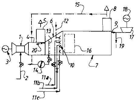
- the single figure schematically represents a
combined plant for the implementation of a process
according to the invention.
The single figure shows a gas turbine unit 1
supplied with gaseous or liquid combustible gas 2, for
example natural gas, and driving a generator 3
delivering electrical energy.
The exhaust gases from the turbine of the gas
turbine unit 1 are sent into a duct provided with a
flue 5. However, according to the invention, the duct 4
emerges in a postcombustion section 6 with a divergent
profile emerging, in turn, in the inlet section of a
recovery boiler 7 provided with a gas flue 8 and with a
steam output circuit 9.
Placed in the postcombustion section 6 are rows
of burners 10 fed, on the one hand, by at least one
steel work gas supply circuit lla, llb, 11c coming from
various steelmaking plants, typically blast furnaces
and/or coke ovens. In one particular embodiment, the
burners 10, or auxiliary burners of the latter, are
able to be fed with gaseous fuel, typically natural
gas, via a supply pipe 12.

CA 02296879 2000-01-24
- 3 -
In addition, according to one aspect of the
invention, the postcombustion section 6 includes,
upstream of the rows of burners 10, injector rails or
nozzles 13 for injecting an oxidizer gas, slightly
compressed by a blower 14. The oxidizer gas is
typically atmospheric air and/or atmospheric air
combined with a portion of the exhaust gases from the
recovery boiler 7, supplied by a pipe 15.
According to one particular aspect of the
invention, in order to take into account any
fluctuations in flow rate and in calorific value of the
steel work gases injected into the burners 10, the
nests of exchanger tubes in the boiler 7, at least in
the front part of the latter, can be selectively
partially protected by heat screens 16, for example of
the water-film type.
Conventionally, the steam available at the
outlet (9) of the recovery boiler 7 is at least partly
expanded in a turbine 17 driving a generator 18,
another portion 19 of the steam being used for other
industrial processes.
The process according to the invention applies
to steelmaking plants, entailing the burning of large
and variable amounts of steel work gases having a low
NCV (Net Calorific Value), which is typically about
3500 kJ/Sm3 but which can fall to values of between
3100 and 3200 kJ/Sm3. When the NCV becomes very low,
the flame of the burners 10 is supported by an
auxiliary stream of natural gas 12 corresponding to
between 3 and 10% of the energy power of the steel work
gases lla, b, c.
Should the gas turbine stop or should there be
peaks in the production of steel work gases, the
combustion of the latter takes place by injecting air
or air and recycled gases introduced via the injector
rails 13 so to maintain the nitrogen oxide and carbon
monoxide emission levels at the outlet of the flue 8 at
low values.

CA 02296879 2000-01-24
- 4 -
Symmetrically, the gas turbine 1 may operate
autonomously, without postcombustion of these exhaust
gases, a structure of pivoting dampers 20 preventing
access of the gases to the postcombustion station 6 and
deflecting them into the actual flue 5 of the turbine
1.
An illustrative embodiment of a plant for the
implementation of such a process will now be given.
The turbine 1 is of the type capable of
producing 70 MWe of electrical power, which propels
into the postcombustion section 6 a stream of exhaust
gases at a rate of 200 kg/s and a temperature of
between 500 and 600 C. The exhaust gases from the
turbine have a residual oxygen content of between 14
and 15% and a water content of greater than 5%. The
steel work gases, typically at a temperature of less
than 80 C, are injected into the burners 10 at a very
low pressure, of less than 1.5 x 10⁵ Pa and typically of
between 1.05 x 10⁵ Pa and 1.3 x 10⁵ Pa. These steel work
gases, with an NCV of about 3400 kJ/Sm3, essentially
consist, besides predominantly nitrogen, of CO (at
least 20%) and CO2 (up to 20%) with a hydrogen content
and a water content which are each less than 2%. The
turbine 1 is designed to deliver an exhaust gas mass
flow rate of at least 2.5 times the maximum flow rate
of steel work gases to be treated. The flow rate of
oxidizer air (pure or mixed) 13 is, should the turbine
stop, greater than 60%, typically approximately 70%, of
the nominal flow rate of exhaust gases from the
turbine.
The process according to the invention makes it
possible to deliver a postcombustion power of between
50 and 200 MWt,,, under conditions indicated in the table
below, for a recovery boiler operating with a steam
pressure of approximately 100 x 105 Pa absolute and a
steam temperature of about 550 C.
I Postcombustion Boiler inlet Boiler inlet Steam flow rate

CA 02296879 2000-01-24
- 5 -
power exhaust-gas exhaust-gas
temperature flow rate
MWtn c kg/s kg/s
50 720 230 50
200 1020 290 100
200 (fresh air) 850 220 60
Although the present invention has been
described in relation to particular embodiments, it is
not limited thereby but is, on the contrary, capable of
modifications and variants which will be apparent to
those skilled in the art. In particular, depending on
the volumes and the number of sources of steel work
gases, the latter may be burnt in at least two plants
of the type described above, these acting in parallel
and/or alternately.

Representative Drawing
A single figure which represents the drawing illustrating the invention.
Administrative Status

2024-08-01:As part of the Next Generation Patents (NGP) transition, the Canadian Patents Database (CPD) now contains a more detailed Event History, which replicates the Event Log of our new back-office solution.

Please note that "Inactive:" events refers to events no longer in use in our new back-office solution.

For a clearer understanding of the status of the application/patent presented on this page, the site Disclaimer , as well as the definitions for Patent , Event History , Maintenance Fee  and Payment History  should be consulted.

Event History

Description Date
Time Limit for Reversal Expired 2020-01-24
Common Representative Appointed 2019-10-30
Letter Sent 2019-01-24
Inactive: Correspondence - Transfer 2008-11-14
Letter Sent 2008-04-29
Grant by Issuance 2007-05-08
Inactive: Cover page published 2007-05-07
Pre-grant 2007-02-20
Inactive: Final fee received 2007-02-20
Notice of Allowance is Issued 2006-10-31
Letter Sent 2006-10-31
Notice of Allowance is Issued 2006-10-31
Inactive: Approved for allowance (AFA) 2006-09-21
Inactive: IPC from MCD 2006-03-12
Amendment Received - Voluntary Amendment 2005-12-15
Inactive: S.30(2) Rules - Examiner requisition 2005-10-25
Amendment Received - Voluntary Amendment 2004-02-19
Letter Sent 2004-01-06
Request for Examination Received 2003-12-09
Request for Examination Requirements Determined Compliant 2003-12-09
All Requirements for Examination Determined Compliant 2003-12-09
Letter Sent 2002-05-09
Application Published (Open to Public Inspection) 2000-08-11
Inactive: Cover page published 2000-08-10
Letter Sent 2000-04-07
Inactive: IPC assigned 2000-03-15
Inactive: First IPC assigned 2000-03-15
Inactive: IPC assigned 2000-03-15
Inactive: Single transfer 2000-03-07
Inactive: Courtesy letter - Evidence 2000-02-29
Inactive: Filing certificate - No RFE (English) 2000-02-28
Filing Requirements Determined Compliant 2000-02-28
Application Received - Regular National 2000-02-24

Abandonment History

There is no abandonment history.

Maintenance Fee

The last payment was received on 2006-12-20

Note : If the full payment has not been received on or before the date indicated, a further fee may be required which may be one of the following

  • the reinstatement fee;
  • the late payment fee; or
  • additional fee to reverse deemed expiry.

Please refer to the CIPO Patent Fees web page to see all current fee amounts.

Owners on Record

Note: Records showing the ownership history in alphabetical order.

Current Owners on Record
L'AIR LIQUIDE, SOCIETE ANONYME POUR L'ETUDE ET L'EXPLOITATION DES PROCEDES GEORGES CLAUDE
Past Owners on Record
EMMANUEL POUSSET
GENEVIEVE MURE
JEROME GIRARD
PASCAL AVART
Past Owners that do not appear in the "Owners on Record" listing will appear in other documentation within the application.
Documents

To view selected files, please enter reCAPTCHA code :


To view images, click a link in the Document Description column. To download the documents, select one or more checkboxes in the first column and then click the "Download Selected in PDF format (Zip Archive)" or the "Download Selected as Single PDF" button.

List of published and non-published patent-specific documents on the CPD .

If you have any difficulty accessing content, you can call the Client Service Centre at 1-866-997-1936 or send them an e-mail at CIPO Client Service Centre.


Document
Description 
Date
(yyyy-mm-dd) 
Number of pages   Size of Image (KB) 
Representative drawing 2000-08-09 1 8
Abstract 2000-01-24 1 21
Drawings 2000-01-24 1 13
Description 2000-01-24 5 215
Claims 2000-01-24 2 56
Cover Page 2000-08-09 1 33
Claims 2005-12-15 2 47
Description 2005-12-15 5 207
Representative drawing 2007-04-17 1 10
Cover Page 2007-04-17 1 40
Filing Certificate (English) 2000-02-28 1 164
Courtesy - Certificate of registration (related document(s)) 2000-04-07 1 113
Reminder of maintenance fee due 2001-09-25 1 116
Acknowledgement of Request for Examination 2004-01-06 1 188
Commissioner's Notice - Application Found Allowable 2006-10-31 1 161
Maintenance Fee Notice 2019-03-07 1 180
Correspondence 2000-02-28 1 16
Correspondence 2007-02-20 1 43