Note: Descriptions are shown in the official language in which they were submitted.
CA 02296932 2000-01-21
Beiersdorf AG
Hamburg
Description
Adhesive tape
The invention relates to an adhesive tape for a flying reel change and to a
splice
method using such an adhesive tape, especially in paper converting machines,
printing
machines and the like.
The flying reel change is a common method, in paper mills or the like, to
replace an old
paper reel which has almost been unwound by a new one without having to stop
the
high-speed machines. In this case, double-sided self-adhesive tapes, so-called
tabs,
are used, which on the one hand are highly sticky and tacky but, on the other
hand,
because of their water-soluble self-adhesive compounds and paper carriers are
not
disruptive when the paper waste is reused in the papermaking machine. These
tabs
are stuck in an elaborate way in zig-zag form at the web start, a procedure
which
demands experienced specialist personnel, there remaining only about 4-5
minutes for
the entire operation because of the high-speed machine.
Although this technology is tried and tested, it has some disadvantages. Thus,
specialist personnel are needed, there is always frantic activity, and the
bonds are also
relatively thick, since in each case two paper layers and the adhesive tab
between
them are the result: a result which is not desired in the paper industry.
For this "pointed bonding" during a flying reel change, there are diverse
products on
the market, so-called tabs, which, in addition to a paper carrier, have a
water-soluble
self-adhesive compound coated on both sides. Such adhesive tapes are on the
market, inter alia under the designation tesafix (Beiersdorf).
Numerous adhesive tapes for such purposes are described in the prior art.
Thus,
EP 418 527 A2 discloses a method of preparing a reel of web-like printing
material for
automatic reel changes and an adhesive strip suitable for this purpose.
DE 40 33 900 Al also describes an adhesive tape suitable for a splice point.
However,
CA 02296932 2007-06-06
2
adhesive areas which are exposed after a splicing method has been carried out
are
disadvantageous.
The non-adhesive covering of otherwise exposed adhesive areas is taught by
US 5,702,555 for more static loadings while securing a reel start, while
DE 196 32 689 A2 discloses such an adhesive tape for dynamic loading during a
splicing method, whose paper carrier cleaves and, with its remains, covers the
adhesive compounds.
Also of this type is an adhesive tape according to DE 196 28 317 Al. likewise
for a
splicing method. This adhesive tape bears, on its non-adhesive rear side, a
double-
sided adhesive tape (6), which has a paper carrier (7) which is suitable for
splicing and
which cleaves (7a, 7b, Figure 3) during the splicing method and covers the
respective
adhesives. This double-sided adhesive tape (6) ends at one side with one side
of the
paper carrier (2), is therefore arranged along one of the long edges of the
adhesive
tape.
In practice, these adhesive tapes also exhibit disadvantages, primarily
because a
splice does not succeed, but rather ends as a break, without any reason for
this being
visible.
The object of the invention was to provide a remedy here.
This is achieved by an adhesive tape and a splicing method as is characterized
in
more detail in the claims. In order to avoid repetitions, reference is
expressly made to
the claims, especially also to relevant preferred embodiments.
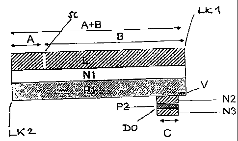
Figure 1 illustrates an example of a cross-section of one embodiment of
adhesive tape according
to the present invention.
Figure 1 shows an exampie of adhesive tape with adhesive front side and non-
adhesive rear side
and two long edges for a flying reel change. The adhesive tape has
a) a paper carrier (P1), which is coated on one side - the front side - with a
self-adhesive
composition (N1),
b) part of the non-adhesive rear side of the paper carrier (P1) being equipped
with a
double-sided adhesive tape (DO) which has, on one side, a paper carrier (P2)
of cleavable paper
CA 02296932 2007-06-06
2A
coated on both sides with self-adhesive composition (N2, N3), and
c) the double-sided adhesive tape (DO) is arranged at a distance (V) of 0.5 to
15 mm
from one long edge (LK) of the adhesive tape.
The adhesive tape may have the distance (V) of 1 to 7 mm or of may have the
distance (V) of 1.5
to 3.5mm.
The self-adhesive compounds (N1, N2, N3) may be contact adhesive compounds
based on
acrylates or rubber.
The self-adhesive compounds (N1, N2, N3) may be water-soluble contact adhesive
compounds
based on acrylates.
The self-adhesive compound (N1) may be covered by a release material (L). The
release
material (L) may be provided with a slit (SC). The slit (SC) may be arranged
at a distance of 20
to 40 mm from that long edge (LK2) of the adhesive tape which is opposite the
long edge (LK1)
close to which the double-sided adhesive tape (DO) is arranged.
The double-sided adhesive tape (DO) may be from 3 to 20 mm wide, and
especially 6 to 12 mm
wide.
The cleavage strength of the paper carrier (P2) may be from 20 to 70 cN/cm,
especially 22 to 60
cN/cm, and quite particularly 25 to 50 cN/cm.
Another embodiment of the present invention provides for a splicing method, in
which an
adhesive tape, for example as that described above, is partly stuck behind the
top paper web of a
reel of paper, while the double-sided adhesive tape on the rear side of the
adhesive tape is for its
part stuck to the paper web beneath it and therefore secures the top paper
web, firstly only part of
the release material possibly located on the self-adhesive compound being
pulled off, so that that
part of the self-adhesive compound needed for the splicing method is still
covered by release
material and, in this state, the paper reel has no free adhesive area, after
which, in order to
prepare the splicing method finally, any remaining release material still
present is removed,
whereupon the new paper reel equipped in this way is placed beside an old
paper reel which has
been almost completely unwound and is to be replaced, and is accelerated to
the same
peripheral speed as the said old reel, is then pressed against the old paper
web, the exposed,
self-adhesive compound of the adhesive tape sticking to the old paper web at
essentially equal
speeds of the paper webs, while at the same time the paper carrier of
cleavable paper cleaves
CA 02296932 2007-06-06
2B
and, with its remains, covers both self-adhesive compounds which were coated
on the said paper
carrier, so that they are non-adhesive.
The adhesive tape may be bonded to the running paper web at right angles or
else at an acute
angle of up to 25 , especially up to 15 .
According to the invention, splices succeed without breaks, the central
feature
constituting the offset or the distance V provided of the double-sided
adhesive tape DO
from the long edge LK of the adhesive tape. This success by comparison with
the prior
art is shown by reference by comparative trials, which are presented in the
table.
Cleavable oaper
The cleavable paper advantageously has a distinctly lower cleavage resistance
than
the paper carrier which has to accommodate the tensile forces. An adequate
CA 02296932 2000-01-21
3
difference is helpful for the functional principle of the product according to
the
invention.
The cleavable papers considered are, for example, the following papers or
paper
composite systems:
= Duplex papers: These papers are commercially available and are used, for
example, in the manufacture of filter materials and wall coverings.
= Easily cleavable papers: The adjustment of the cleavage work is carried out
via the
consolidation of the paper fibre structure. The lower the consolidation, the
lower the
cleavage work.
Suitable paper types are, for example, machine-finished papers calendered on
one
side or else highly-calendered kraft papers.
= Sized gaper systems: The cleavage work is adjusted via the chemistry of the
adhesive size. The size should have penetrated into the paper only to an
insignificant extent.
Clean cut edges are also helpful for the aims of the present invention. During
the
cutting operation, no compound should be squeezed out. In particular, the
cleavable
attachment area of the cleavable material should not be covered by contact
adhesive
compound.
The amount by which the cleavable material is set back, or the distance V,
should be
0.5 - 15 mm according to the invention, especially 1 - 7 mm and quite
particularly
1.5 mm - 3.5 mm.
Diverse cleavable paper systems are considered for the cleavable paper, such
as
= Duplex papers (papers laminated together in a defined manner), the cleavage
process proceeds extremely homogeneously, no stress peaks are produced, for
example as a result of inhomogeneous consolidation. These papers are used for
the manufacture of wall coverings and filters.
= Easily cleavable paper systems
= Highly consolidated papers sized together in a defined way (=* papers with a
high
cleavage strength). Sizing can be carried out, for example, with starch,
starch-
containing derivatives, wall covering adhesives based on methylcellulose
(Methylan O, Henkel KGaA, Dusseldorf) or else based on polyvinyl alcohol
derivatives.
CA 02296932 2000-01-21
4
= The width of the carrier of the cleavable paper is preferably 3 - 20 mm,
especially
6-12mm.
All basic types of contact adhesive compound are considered as the self-
adhesive
compounds, especially
= acrylates (water-soluble and non-water-soluble)
= natural rubber compounds, synthetic rubber compounds
The splicing method, here the sticking using the splicing tape, can in
particular be
carried out in such a way that the adhesive tape is stuck to the running web
at right
angles (disadvantage: the cleavable paper system must cleave completely into
secondary fractions), but also at an acute angle (advantage: the cleaving
process runs
as a wave through the adhesive tape), especially up to 25 , above all up to
15 .
The drawing shows a schematic illustration of an adhesive tape according to
the
invention in cross section, and is therefore intended to explain the invention
by way of
example. The reference symbols are explained in the claims.
CA 02296932 2000-01-21
Test methods
Measuring the cleavage strength (internal bond strength) of papers
Purpose and area of application
Testing the strength of paper or other materials built up from fibres in the Z
direction.
The cleavage strength is determined.
The cleavage strength is the force which has to be overcome in order to cleave
a
paper element in the Z direction.
Principle of the method
Two adhesive tapes are applied to the paper to be tested, located opposite
each other,
and are pulled apart at an angle of 180 C in the tensile testing machine. The
force to
be overcome in order to cleave the paper is the cleavage strength.
Instruments and atmospheric testing conditions
Tensile testing machine
Blade or strip cutter 15 mm wide
Hand-held roller 2 kg
Atmospheric testing conditions: 23 +/- 1 C, 50 +/- 5% relative humidity
Materials
Adhesive tape, such as test tape 7475
Width 20 mm, strips about 20 cm long
Test samples
DIN A4 sheets
The samples must be conditioned for at least 16 hours under standard
atmosphere
conditions.
Carrying out the test
Two adhesive tapes are placed on the paper to be tested from both sides,
located
opposite each other, and are smoothed lightly with a finger in order to avoid
air
inclusion.
The hand-held roller is then used to roll the composite twice on both sides,
in order to
achieve a satisfactory adhesive strength.
The bond is to be produced in such a way that on one side, the ends of the
adhesive
tape project beyond the test element and, by being folded, can be stuck to
each other
to form a grip.
The testing direction may be the running direction or transverse to the
running
direction of the test element, depending on the aim of the test.
CA 02296932 2000-01-21
6
Using a steel rule, strips of a length of about 20 cm and 15 mm width are cut
centrally
from the composite. The two grips of the projecting adhesive tape are then
pulled apart
by hand until cleavage of the paper specimen can be detected.
The test element is then clamped into the tensile testing machine by the
grips, freely
suspended at the top and the bottom, and the rest of the strip is pulled apart
at a
constant speed of 300 mm/min.
In the case of very thin papers, care should be taken that the result is not
falsified by
the fact that the opposite edges of the adhesive strip have contact with the
edge of the
test element and stick to it.
Evaluation and assessment
The cleavage strength of the paper is specified in cN/cm.
The average of 5 values determined is specified.
Application examples
The following examples describe trial products tried out for a flying reel
change, the
spiicing conditions and the splicing results. The product constructions tried
are
illustrated in Table 1.
The drawing describes the associated product construction.
Description of the paper systems used:
The following coating base papers were used for the splicing trials:
=[ A] Coating base paper (grammage 33 g/mz, thickness 58 pm)
e.g.: Stora Kabel GmbH, 58099 Hagen
=[ B] Coating base paper (grammage 60 g/m2, thickness 80 pm)
e.g.: Stora Uetersen GmbH, 25436 Uetersen
=[ C] Coating base paper (grammage 134 g/mz, thickness 167 pm)
e.g.: Sappi Alfeld AG, 31061 Alfeld
The following cleavable papers were used for the trial products:
= [ D ] Duplex filter paper
= Grammage 51 g/mz, thickness 90 pm
Cleavage work, transverse 34 - 44 cN/ cm
CA 02296932 2000-01-21
7
=[ E] Machine-finished paper calendered on one side
Grammage 57 g/mz, thickness 74 pm
Cleavage work, transverse 33 - 38 cN/ cm
=[ F] Highly calendered kraft paper
Grammage 50 glmz, thickness 57 pm
Cleavage work, transverse 40 - 45 cN/ cm
=[ G] Sized paper composite system with a defined cleavage work.
Two machine-calendered base papers were bonded together using a size
containing
starch. Grammage in each case 54 g/m2, thickness 66 pm. The cleavage work of
the composite, transverse was 28 - 32 cN/ cm.
The following carrier papers were used for the trial products:
= [ H ] Machine-calendered base paper
Grammage 54 g/m2, thickness 66 pm, maximum transverse tensile strength
40N/15mm
='[ I] one-side-coated calendered base paper
Grammage 59 g/m2, thickness 52 pm, maximum transverse tensile strength
30N/15mm
=[ J] Two-side-coated, consolidated, printable decor paper
Grammage 80 : g/m2, thickness 62 pm, maximum transverse tensile strength
30N/15mm
=[ K] One-side-double-coated, woodfree, high-gloss kraft paper
Grammage 63 g/m2, thickness 51 pm, maximum transverse tensile strength
30N/15mm
CA 02296932 2007-11-08
m
0
M
W AN MO 0) 0M2CO~ f~ ')M~N f'~M.- C~GO0Ll)~ X
m
G
W v> ~ C) p o m o C.
LO ~
hN~O)O)~tnSCO V MOM MN UO)lf)M X
C)
2
G
EOf
X
W it N M O) 00) C 0 2 C00 V M 0 M COe) O m~U'ico X
m
O. It
E q
W Wf H O 0 O <O O O O ~ (00
hNtnO)O)' OI(O V MCIM mN mLf)~Or X
_
Q.
E
K
W tiN ~CO 0) 0M0 -~M M~M c0~) N NOO X
m
O
E <G ~
W O O O O O N O O O O N d
GOMLf)O)O)'ITCOCpCl) Cl) LL 'IT C)N mr0 X
Qm
EYY M
X
W OODMtOC)O)00l~l)Y~f)M CO) WM Mr ~00000 X
101
m
Q
E0
LA LO 0~2 O O (C O O O O ~ O t >i
t~NLO OT ~(O~ MLL MN m O X ~
N
Gf N CL
N
E M a C
x E 'C
00 w ~ N~.N- W tf~ COC V M LL0 d O N 04 O0 X U ~
y j
E
O. E w
E N O O 0
W M N ln c 0) M 2 CO 114, M 0 C') M ~ m
X C
X
41 ~ fC
Q E E
E E
~ M O
y x O~ONO O (00 OM O ~0~ X M
W r- N Ln 0) v
~ Ln2cov m M m
c~ cO)
'N vc%to
N C_ t
E C m r r r r N N N M 0 ~ C
~ QaQmC~JJZddd 2dd 2> ~ 0~_ T
~ ~y N
W b E
~0y O
E E E N O a
o EEEEEZEEE~ EEZ EE E~ ~ m
~ E E E E 0 sZ -~ 0 E ~ Eo c~ o -
E o
f c
Z ~o
r. N U M M M LL y~ Iv
V U~ N .p N y y M~ y 7 N
~ ~ - 29
t6 O -
m
.-õ OT V y~ cp N~ 7 ~
E y m:: 0)2 y C WZ Et
E~~ rn
o m~ ~ ~a ~ N ZLL
y y Ea=c N~~ w0 ~oc~S~
M ~='- c~' > 0 a) ' 0 ,-a co ~uy, odo~~rn
E d (0 0 o~ ~ w L~'O y~ C~ y C
~ O N y O Y > N y,FO O E y f0
m~ +~ vyiEaiE o~ai o oH~~~c
M m U a~ N c~ ~C~ m,r> ~p m ~ w Q'a=X ca ~
~ y C C ' C C L
N ~ L L C f6 ~ wp E d. .U ~ C1 ~ G.
a L M
G.
e vv vv ~ d- H'X m y ~~v~ 2 Um
~~~~~~~vf6~O aa3v~~ cncn~NM~~CO