Note: Descriptions are shown in the official language in which they were submitted.
CA 02296955 2000-O1-25
CROSS REFERENCE TO RELATED APPLICATION
This application claims the priority of Swiss
Application No. 1999 0161/99 filed January 29, 1999, which
is incorporated herein by reference.
BACKGROUND OF THE INVENTION
Packing machines using plastic film wrappers
frequently include sealing shoes with cooperating counter,
shoes for providing sealed seams on superposed plastic
films (sheets) forming a packing hose. The sealing shoe or
both the sealing shoe and the counter shoe are heated to a
temperature above the melting temperature of the
thermoplastic packing sheet, and the shoes are pressed ta'
one another to seal the superposed plastic films positioned
between the two shoes.
The output capacity of the above-outlined systems i~
necessarily limited. The heat is conducted through the
film into the sealing zone. If the sealing temperature is
too low, insufficient heat is transferred to the sealing',
layer. If, on the contrary, the sealing tools are too hctit,
the film tends to adhere to the contact faces of the tools.
Dependent on the film thickness.and the operating cycle,
_2_
CA 02296955 2000-O1-25
the parameter range in which a reliable operation is
ensured might be extremely narrow. In case of rotary
transverse sealing shoes, the sealing period depends from
the feeding speed of the film. At high feeding speeds the
sealing period is too short to produce a stable sealed
seam. Such a boundary speed may be increased by providing
that the transverse sealing shoe co-travels along a linear
trajectory with the traveling film as described, for
example, in International Application WO 96/17720. For
this purpose, however, a complex mechanical system is
required which often leads to vibrations, wear and
operational disturbances.
In general, the sealed seam of a thermoplastic
material may be exposed to stresses only after the
temperature has dropped below the melting temperature.
Since, because of the contact with the hot sealing tool,
the entire seam volume is heated, in addition to the speed
of the energy supply, the cooling phase also limits the
minimum required period to ensure that the sealed seam may
be exposed to stresses.
SUMMARY OF THE INVENTION
It is an object of the invention to provide an
2S improved apparatus of the above-outlined type with which a
-3-
. CA 02296955 2000-O1-25
rapid sealing may be performed and which is of simple
construction.
This object and others to become apparent as the
specification progresses, are accomplished by the
invention, according to which, briefly stated, the
apparatus for sealing films together along a path includes
a sealing shoe and a counter shoe defining a clearance
through which the films pass. The sealing shoe includes an
elongated optical energy source having a length dimension
l0 oriented generally parallel to the sealing path; a
reflector for focussing light emitted by the energy source;
a window transparent to the light and having an outer
surface adapted to be oriented toward the counter shoe for
sealing the films by the light; and a firing arrangement
for activating the energy source. The window and the
counter shoe are urged toward one another.
BRIEF DESCRIPTION OF THE DRAWINGS
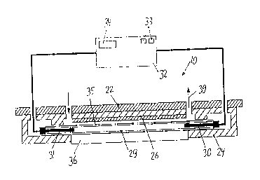
Figure 1 is a sectional end elevational view of a
preferred embodiment of the invention.
Figure 2 is a sectional side elevational view of the
construction shown in Figure 1.
Figures 3 and 4 are sectional side elevational views
of two further preferred embodiments of the invention.
-4-
CA 02296955 2000-O1-25
Figure 5 is a fragmentary enlarged sectional
elevational view of a variant of Figure 4.
Figures 6a through lla are cross-sectional views of
superposed plastic films of various properties depicted
during irradiation with optical energy for sealing the
films to one another.
Figures 6b through llb are cross-sectional views of
the superposed plastic films shown in the respective
Figures 6a through lla, depicted in a sealed state after
irradiation with optical energy.
DESCRIPTION OF THE PREFERRED EMBODIMENTS
The apparatus shown in Figures 1 and 2 includes a
sealing shoe 10 and a counter shoe 11 which are rotatable
in synchronism in opposite directions about two respective,
parallel spaced axes 12, 13 in the direction of respective
arrows 14a and 14b. The packing hose 15 which is advanced
in the conveying direction A between the sealing shoe 10
and the counter~shoe 11 contains uniformly spaced products
16 to be packaged. The hose 15 is composed of a
thermoplastic film 18 and has a longitudinal sealed seam
(not shown) . By means of transverse severing through the
middle of the transverse sealed seams, individual packages
17 are obtained.
-5-
CA 02296955 2000-O1-25
The sealing shoe 10 includes a cross-sectionally
rectangular rotor 20 rotatable about the axis 12 and an
optical unit 21 which includes a carrier 22 radially
displaceable on the rotor 20 and biased by a spring 23
radially outwardly against a non-illustrated stop. A
prismatic housing 24 made of an insulating material such as
a plastic is secured to the carrier 22. Further, in the
housing 24 an aluminum reflector 26 is mounted, having a
cylindrical reflecting surface 27 which is cross-
sectionally elliptical. A cylindrical gas discharge flash
lamp such as a xenon lamp is arranged coaxially with the
focal axis 28 of the surface 27, extending parallel to the
rotary axis 12. The two electrodes 30, 31 of the lamp 29
are connected to a high-voltage pulse generator 32 which
has a condenser switching circuit, setting elements 33 for
setting parameters such as voltage, current intensity,
duration of pulse and pulse shape as well as indicator
elements 44 for displaying the set parameters. The space
35 between the lamp 29 and the reflector 26 is closed by a
transparent window 36 which is preferably of a scratch
proof material, such as sapphire glass. The approximately
cylindrically curved outer surface 37 of the window 36 has
a central flattened portion 38 which is oriented
perpendicularly to the plane containing the axes 12, 28.
The space 35 is connected to a coolant circuit 39; the
-6-
' . ~ CA 02296955 2000-O1-25
coolant may be air or a transparent, electrically
insulating liquid such as de-ionized water.
The counter shoe 11 has a rotor 42 having a
rectangular cross section. A holder body 43 is radially
displaceably mounted on the rotor 42 and is biased radially
outwardly by a spring 44 against a stop. The arcuate
(convex) counter face 45 of the holder body 43 has a
central flattened portion 46.
In the description which follows, the operation of
the above-described apparatus will be set forth.
The sealing shoe 10 and the counter shoe 11 run in
synchronism in opposite directions. The circumferential
speed of the two surfaces 37 and 45 is approximately the
same as the advancing speed of the tubular hose 15 at least
when the. surfaces 37 and 45 press together the two film
layers of the hose 15 running between the sealing shoe 10
and the counter shoe 11. The rotary angle of the rotors
20, 42 is synchronized with the longitudinal feed in such a
manner that the window 36 of the sealing shoe 10 and the
holder body 43 of the counter shoe 11 at all times engage
the hose 15 between two products 16. The flash lamp 25 is
fired at the moment when the axes 12, 13 and 28 lie in a
common plane, that is, the flattened portions 38 and 46
press the hose 15 together. By means of a pulsed
electrical field between the two electrodes 30, 31 in the
' . ~ CA 02296955 2000-O1-25
discharge volume, a gas is converted into an electrically
conducting plasma by impact ionization, and the plasma is
heated up by the electric current. The light emission
consists of a black body radiation with a color temperature
of up to approximately 10,000 K which is. superposed by the
characteristic spectral lines of the ionized gas; this
corresponds to a wide spectral emission of 160-2500 nm.
The emission proceeds from the upper surface of the
ignited, light-impervious plasma.
The energy radially emitted by the lamp 29 is
reflected by the elliptical reflecting surface 27 on the
second focal point of the ellipse. Such second focal point
is situated approximately on the flattened portion 38 of
the window 36 or, stated differently, at a location which
is at a distance from the hose 15, corresponding to a
single or dual thickness of the film 18 of the hose 15. In
this manner more than one-half of the energy radiated by
the lamp 29 is concentrated on the focal line at the
surface in the middle or on the underside of the hose 15 so
that on the focal line an energy density of more than 2
J/cm2, up to 30 J/cm2 is obtained, resulting in a very high
degree of efficiency. Dependent on the thickness of the
film of the hose 15, a pulse duration between 50
microseconds and 10 milliseconds is required. The desired
spectrum of the emitted radiation depends from the type of
_g_
CA 02296955 2000-O1-25
the film 18 because the absorption coefficient of the
material is dependent from the wave length. The radiation
spectrum is relatively wide; it has, however, a maximum
which depends from the current intensity. In case of 1,000
A/cm2 the maximum is, for example, in the visible spectral
range and shifts to the ultraviolet range upon an increase
to 10, 000 A/cm2.
Assuming an advancing speed of 1 m/s in the direction
A, a circulating radius of 8 cm of the surface 38 and a
flash duration of 0.1 millisecond, there is obtained, for
example, a rotary angle of only 3.5 arc minutes of the
sealing device 10 during the duration of the flash. The
sealing occurs thus extraordinarily rapidly and thereafter
the surfaces 38, 45 are still pressed together for a
i5 sufficiently long period to result in a rapid cooling of
the sealed seam. In this manner, very high output rates
may be achieved. Large energy quantities may be introduced
on purpose into the sealed seam. The pressing components
of the shoes remain cold and cool the sealed seam
immediately. Thick transparent material may be welded onto
any desired absorbing material. The device is adapted also
for a contactless sealing without a mechanical contact
between the device and the films 18.
The embodiment according to Figure 3 differs
principally from that of Figures 1 and 2 in that the
-9-
CA 02296955 2000-O1-25
reflector 26 and the lamp 29 are stationary and the window
36 is mounted on a carrier 51 which rotates about an axis
52 which is parallel to the axis 28 and which lies in a
plane which contains the axes 28 and 13. The space 35 may
be closed by a further window 53 shown in a dash-dotted
line in Figure 3. This arrangement makes possible to
provide coolant circuit 39. This embodiment has above all
the advantage that the flash lamp 29 is less exposed to
shocks and that the terminals at the generator 32 and the
coolant circuit 39 are of simpler construction.
In case the hose 15 is intermittently advanced, the
counter shoe 11 and the window 36, instead of being
rotated, may be moved linearly in suitable guides in the
direction of the arrow 54 perpendicularly to the conveying
direction A.
The device according to Figure 4 differs from that of
Figure 3 in that the reflector 26 rotates whereas the flash
lamp 29 remains stationary. The holder body 43 has a
transparent window 61 and a reflecting, elliptical-
cylindrical surface (counter reflector) 62 whose cross
section complements the upper surface 27 of the reflector
26 in the focal point to an almost complete ellipse. The
focal axis 28 of the reflector 26 is the rotary axis 12 of
the reflector 26. The other focal point 63 lies in the
middle of the two films 18 to be welded together. This
- 10-
' ~ CA 02296955 2000-O1-25
embodiment is particularly adapted for sealing partially
transparent films 18 because the light which is directly
radiated from the lamp 29 to the window 36 is concentrated
by the upper surface 62 on the focal line 63.
Figure 5 shows a variant of the reflecting surface 27
of the reflector 26 which is structured in accordance with
U.S. Patent No. 4,641,315 and whose cross section is an
involute. Such a cross-sectional configuration is useful
mainly in the vicinity of the flash lamp 29 because of its
l0 radiation characteristics (opaque surface emitter).
The device according to the invention may also be
driven in such a manner that a first flash produces a
sealed seam and immediately thereafter a second, shorter
but more intensive flash severs the hose 15 in the middle
of the just-formed sealed seam.
The six figure pairs 6a,b through lla,b show variants
of the films 18 to be sealed. The left-hand illustration
of each pair shows the films during application of optical
energy, and the right-hand illustration of each pair shows
the films provided with a sealed seam.
The films of Figures 6a, 6b are weakly absorbing.
Particularly the apparatus according to Figure 4 is adapted
to provide them with a sealed seam.
Figures 7a, 7b show the sealing of substantially
absorbing films 18. In this case the heat admission to the
-11-
CA 02296955 2000-O1-25
sealed seam 58 is effected by heat conduction by and
through the upper film 18.
In the variant according to Figures 8a, 8b at least
one of the films 18 is a compound film having an outer,
transparent layer 59 and an inner, light-absorbing layer
60.
According to the variant shown in Figures 9a, 9b the
films 18 are transparent and an additional, light-absorbing
strip 61 is sealed in between.
In the variant according to Figures 10a, lOb the film
18 facing the lamp 29 is transparent while the other film
18 is light absorbing.
In the variants according to Figures 8a, 8b; 9a, 9b;
and 10a, lOb the energy is directly introduced at the
location to be welded. In this manner, the sealing process
is particularly rapid and efficient.
In the variant according to Figures lla, 11b both
films 18 are transparent; the holder body 43 and/or its
upper surface 45 is then light absorbing.
It will be understood that the above description of
the present invention is susceptible to various
modifications, changes and adaptations, and the same are
intended to be comprehended within the meaning and range of
equivalents of the appended claims.
- 12-