Language selection

Search

Patent 2297132 Summary

Third-party information liability

Some of the information on this Web page has been provided by external sources. The Government of Canada is not responsible for the accuracy, reliability or currency of the information supplied by external sources. Users wishing to rely upon this information should consult directly with the source of the information. Content provided by external sources is not subject to official languages, privacy and accessibility requirements.

Claims and Abstract availability

Any discrepancies in the text and image of the Claims and Abstract are due to differing posting times. Text of the Claims and Abstract are posted:

  • At the time the application is open to public inspection;
  • At the time of issue of the patent (grant).
(12) Patent: (11) CA 2297132
(54) English Title: SOLID PHASE EXTRACTION PLATE
(54) French Title: PLAQUE D'EXTRACTION EN PHASE SOLIDE
Status: Expired and beyond the Period of Reversal
Bibliographic Data
(51) International Patent Classification (IPC):
  • B01L 3/00 (2006.01)
(72) Inventors :
  • BLEVINS, DENNIS D. (United States of America)
  • SCHULTHEIS, STEPHEN K. (United States of America)
  • HALL, DAVID O. (United States of America)
(73) Owners :
  • AGILENT TECHNOLOGIES, INC.
(71) Applicants :
  • AGILENT TECHNOLOGIES, INC. (United States of America)
(74) Agent: GOWLING WLG (CANADA) LLP
(74) Associate agent:
(45) Issued: 2007-02-06
(86) PCT Filing Date: 1998-08-03
(87) Open to Public Inspection: 1999-02-11
Examination requested: 2002-09-19
Availability of licence: N/A
Dedicated to the Public: N/A
(25) Language of filing: English

Patent Cooperation Treaty (PCT): Yes
(86) PCT Filing Number: PCT/US1998/016107
(87) International Publication Number: WO 1999006148
(85) National Entry: 2000-01-18

(30) Application Priority Data:
Application No. Country/Territory Date
08/905,811 (United States of America) 1997-08-04

Abstracts

English Abstract


A solid phase extraction plate (10) includes a unitary tray (12) having a
plurality of spaced-apart discrete upstanding chambers (14)
molded therein with each chamber (14) having a top opening (16) and a bottom
nozzle (18) with downwardly tapering sidewalls (24)
extending between the top opening (16) and the bottom nozzle (18). A plurality
of solid phase extraction disks (28) are provided and one
secured in each of the plurality of chambers (14) without the use of frits or
retainer rings utilizing instead tapered sidewalls (24) of the
chamber (14) for enabling a press fit of the disks (28) therein.


French Abstract

Selon cette invention, une plaque d'extraction (10) en phase solide comporte un plateau unitaire doté d'une série de chambres (14) séparées, saillantes et moulées dans ce plateau, chaque chambre (14) étant dotée d'un orifice supérieur (16), d'une buse inférieure (18) et de parois latérales (24) s'effilant vers le bas et s'étendant entre ledit orifice supérieur (16) et ladite buse inférieure (18). Cette plaque comporte une série de disques d'extraction (28) en phase solide. Chacun de ces disques est fixé à l'une des chambres (14), sans frittes de scellement ou anneaux de retenue, mais grâce aux parois latérales (24) effilées de la chambre (14) qui permettent de former un ajustage serré des disques (28) au sein de cette chambre.

Claims

Note: Claims are shown in the official language in which they were submitted.

Claims:
1. A solid phase extraction plate comprising:
a unitary tray having a plurality of spaced
apart discrete upstanding chambers molded therein, each
chamber having a top opening and a bottom nozzle
a plurality of solid phase extraction disks,
each one of the plurality of disks being sized for press
fitting between sidewalls of one of the plurality of
chambers proximate the bottom nozzle in order to hold the
disks within the chambers by frictional engagement with
the sidewalls, each disk comprising a nonpolar extraction
medium containing silica particles bonded with
hydrophobic groups; and
fritless means for enabling each disk to be
press fit into a corresponding chamber, said fritless
means comprising tapered sidewalls in each chamber.
2. The solid phase extraction plate according to
claim 1 wherein each of the chambers has a circular cross
section.
3. The solid phase extraction plate according to
claim 1 further comprising means for spacing each disk
from a corresponding nozzle.
4. The solid phase extraction plate according to
claim 2 wherein the means for spacing each disc from a
corresponding nozzle comprises a step formed in the
sidewall proximate the corresponding nozzle.
5. The solid phase extraction plate according to
claim 1 wherein each of the plurality of chambers are
identical to one another.
8

Description

Note: Descriptions are shown in the official language in which they were submitted.


CA 02297132 2000-O1-18
WO 99/06148 PCT/US98/16107
SOLTD PHASE EXTRACTION PLATE
The present invention generally relates to assay
assemblies for use in the analysis of liquids by a
batch process and is more particularly directed to a
solid phase extraction plate for the determination of
chemical, bio-chemical or biological nature of various
liquids.
Because of the need for the analysis, or assay, of
a great number of small quantities of liquids, array
trays and assemblies have been developed 'whereby
individual samples of test liquid are prepared and
subjected to analysis by multi-test processing
utilizing various extraction mediums.
Devices of this type may include a separation
medium to which the liquid for analysis are subjected
with the medium serving to remove solid/particulate
matter from the liquid by filtration or serving as a
. form of chromatographic medium for selectively
separating or indicating a particular characteristic of
the fluid being assayed.
A typical prior art solid phase extraction plate
assembly is shown in US Patent No. 5,417,923. The
assay trays typically have a plurality of wells, for
example, 96, arranged in rows and columns in which the
solid phase extraction medium is placed and
sequentially treated with liquid reagents and washes
involved in the assay of interest.
It should be appreciated that this type of assay
tray typically has dimensions in the order of 3 inches
1

CA 02297132 2000-O1-18
WO 99/06148 PCT/US98/16107
by 5 inches, hence, a 96 compartment, or well, assay
tray has very small compartment diameters. Allowing
for supporting for wall structure, a typical 96 well
assay tray having the wells arranged and a typical 8 x
12 configuration will have well diameters in the order
of 0.3 inches.
Accordingly, while the tray with the compartments,
or wells, may be formed by injection molding, the
insertion of separation medium into each well and the
physical requirement of positively supporting the
medium within each individual well cari be a tedious
time-consuming procedure.
Typically, not only is it required to dispose a
separate medium in each well, but also a means for
fixing or holding the medium in the well in a position
suitable for separation, or reaction, with liquids
later disposed in the well for assay purposes.
Heretofore, separation mediums, either in
particulate form or in slug, or disk, form have been
supported in wells structure by means of frits, or
retaining rings, see for example, the structure shown
in US Patent Nos. 5,205,989, 5,264,184, 5,283,039 and
5,417,923.
Given the size of the wells, or compartments, in
the 96 well assay tray, it can be easily appreciated
that the assembly of the small extraction mediums and
retainer rings is extremely tedious and, of course,
time-consuming and expensive.
The present invention provides for a solid phase
extraction plate having simplified construction which
does not require the use of frits, or the like, and
2

CA 02297132 2000-O1-18
WO 99/06148 PCT/US98/16107
accordingly, enables significant cost-savings in the
assembly thereof.
SUMMARY OF THE INVE~iTION
A solid phase extraction plate in accordance with
the present invention generally includes a unitary tray
having a plurality of spaced-apart discrete, upstanding
chambers molded therein. Each chamber includes a top
opening and a bottom nozzle with downwardly tapering
sidewalls extending between the top opening and the
bottom nozzle. A plurality of solid phase extraction
disks are provided with one of the plurality of disks
press fitted between the sidewalls of one of the
plurality of changes proximate the bottom nozzle.
Thus, the tapering sidewalls of the chamber
provide a fritless means for receiving one of the
plurality of solid phase extraction disks. Because no
separate retaining rings, or frits, are required to
support or maintain the solid phase extraction disks
within the chambers, assembly of the solid phase
extraction plate is greatly simplified.
More particularly, each of the chamber may have a
circular cross section and, in addition, means may be
provided for spacing each of the disks from a
corresponding nozzle. The structure corresponding to
this means for spacing includes a step formed in the
sidewall of the chamber proximate the corresponding
nozzle. Importantly, this structure also provides
means for enabling fluid flow through each of the disks
over a diameter of the disk which is greater than the
diameter of a nozzle entry port. In this manner,
efficient use of each disk is enabled by providing
exposed areas on each side of the disk to facilitate
3

CA 02297132 2000-O1-18
WO 99/06148 . PCT/US98/16107
fluid flow therethrough. This should be contrasted
with prior art devices in which a large portion of the
extraction medium is masked by abutment with supporting
structure.
While each of the chambers may have differing
cross sections or diameter, it is preferable that each
of the chambers be identical in order to facilitate
assembly of the extraction disks therein.
BRIEF DESCRIPTION OF THE DRAWINGS
The advantages and features of the present
invention will be better understood by the following
description when considered in conjunction with the
accompanying drawings, in which:
Figure 1 is a top plan view of a solid phase
extraction plate in accordance with the present
invention generally showing a unitary tray having a
plurality of spaced apart discrete upstanding chambers
molded therein;
Figure 2 is a bottom view of the unitary tray
shown in Figure 1;
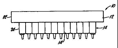
Figure 3 is a side view of the tray shown in
Figures 1 and 2;
Figure 4 is a section of the tray taken along the
line 4-4 of Figure 1;
Figure 5 is a part sectional view taken along the
line 5-5 of Figure 1; and
4

CA 02297132 2000-O1-18
WO 99/06148 . PCT/US98/16107
Figure 6 is a detail of a bottom portion of one of
the chambers showing the disposition of an extraction
disk therein.
DETAILED DESCRIPTION
Turning now to Figures 1-3, there is shown a solid
phase extraction plate 10 in accordance with the
present invention, which generally includes a unitary
to tray 12 having a plurality of spaced apart discrete
upstanding chambers 14 molded therein. The tray 12 may
be molded from any suitable material such as, for
example, polypropylene.
Each chamber 14 has a top opening 16 and a bottom
nozzle 18, see also Figures 4-6.
Importantly, sidewalls 24 of the chambers 14 taper
downwardly from the openings 16 to the nozzle 18.
As most clearly shown in Figure 6, a plurality of
solid phase extraction disks 28 are press fitted
between the sidewalls 24 of each of the plurality of
chambers 14 proximate the bottom nozzle 18. Any number
of different extraction mediums may be utilized and the
disk such as, for example, a nonpolar extraction medium
containing silica particles bonded with hydrophobic
groups, available from Ansys, Inc., Irvine, California,
under the trade name SPEC~ may be utilized.
Because of the tapering nature of the sidewalls
24, the disks 28 are held in position proximate the
nozzle 18 by frictional engagement with the side walls
24 and are disposed within the chambers 14 by use of a
set of ramrods, not shown. This facilitates placement
of the disks 28 in all of the chambers 14
simultaneously. Because no frits or retaining rings
5

CA 02297132 2005-11-03
(not shoam) are utilised, assembly of the solid phase
- extraction plate 10 is greatly facilitated. The use of
polypropylene with wall thickness hereinafter
specified provides sufficient resiliency to maintain
the disks 28 within the chambers 14 by frictional
contact therewith.
As a specific example, the solid phase extraction
plate l0 may include the plate 12 having dimensions of
about 3 inches wide by 5 inches long, with 96 of the
chambers 14 arranged in an array, that is, 8 chambers
wide by 12 chambers long.
Importantly, as shown in Figure 5, the chambers 14
taper with a top inside diameter Dt of about 0.325 plus
or minus 0.003 inches to a bottom inside diameter Db of
0.294 plus or minus 0.001 inches. This enables the
disk 28, which has a thickness of about 0.04 inches and
a diameter slightly larger than 0.294 inches to be
easily inserted through the top opening i6 and~forced
to a bottom 30 of each chamber proximate the nozzle 18.
Sidewall 24 thicknesses are varied to produce this
taper inasmuch as the chambers are unitarily formed in
the tray l2~by any suitable molding operation with the
sidewalls having a nominal thickness of about 0.032
inches. Overall, the chambers may have a height, H, of
about 1.18 inches as indicated in Figure 4. A
surrounding flange 32 is provided for alignment of the
chambers 1~4 with corresponding and accompanying assay
apparatus (not shown) for depositing liquid into the
openings 16 of the chambers 14.
Turning again to Figure 6, it can be seen that the
nozzle is includes an entry port 36 which is smaller
than the bottom diameter Db of the chamber l4.
6

CA 02297132 2000-O1-18
WO 99/06148 PGT/US98/16107
In order to support the disk 28 proximate that
nozzle and create a void 40 therebetween, which may
have a thickness T of about 0.04 inches, the disks 28
are supported by steps 44 formed in the sidewall 24
proximate the nozzle 18. The step 44 not only provides
a means for spacing each disk 28 of the nozzle 18, but
also provides a means for enabling fluid flow through
each disk 28 over a diameter greater than the nozzle
entry port 36 diameter. Because the disk 28 is not
held against the top 46 of the nozzle 18, which is part
of the bottom 30 of the chamber i4, flow may pass
through the disk 28 over almost its entire surface
area. Only where contact with the step 44 is made is
straight through flow not enabled. This arrangement
significantly improves the efficiency, thus an area
having a diameter D~ as shown in Figure 6 is available
for transfer of fluids through the disk, rather than
the size of the nozzle entry port 36.
Although there has been hereinabove described
specific arrangements of a solid phase extraction plate
in accordance with the present invention for the
purpose of illustrating the manner in which the present
invention can be used to advantage, it should be
appreciated that the invention is not limited thereto.
Accordingly, any and all modifications, variations or
equivalent arrangements, which may occur to those
skilled in the art, should be considered to be within
the scope and spared of the present invention as
defined by the appended claims.
7

Representative Drawing
A single figure which represents the drawing illustrating the invention.
Administrative Status

2024-08-01:As part of the Next Generation Patents (NGP) transition, the Canadian Patents Database (CPD) now contains a more detailed Event History, which replicates the Event Log of our new back-office solution.

Please note that "Inactive:" events refers to events no longer in use in our new back-office solution.

For a clearer understanding of the status of the application/patent presented on this page, the site Disclaimer , as well as the definitions for Patent , Event History , Maintenance Fee  and Payment History  should be consulted.

Event History

Description Date
Time Limit for Reversal Expired 2015-08-03
Letter Sent 2014-08-04
Letter Sent 2011-02-15
Grant by Issuance 2007-02-06
Inactive: Cover page published 2007-02-05
Inactive: Final fee received 2006-11-23
Pre-grant 2006-11-23
Notice of Allowance is Issued 2006-06-14
Letter Sent 2006-06-14
Notice of Allowance is Issued 2006-06-14
Inactive: Approved for allowance (AFA) 2006-01-31
Amendment Received - Voluntary Amendment 2005-11-03
Inactive: S.30(2) Rules - Examiner requisition 2005-05-26
Amendment Received - Voluntary Amendment 2003-01-10
Letter Sent 2002-10-18
All Requirements for Examination Determined Compliant 2002-09-19
Request for Examination Received 2002-09-19
Amendment Received - Voluntary Amendment 2002-09-19
Request for Examination Requirements Determined Compliant 2002-09-19
Letter Sent 2002-08-15
Inactive: Single transfer 2002-06-20
Letter Sent 2000-07-05
Inactive: Single transfer 2000-04-13
Inactive: Correspondence - Formalities 2000-04-13
Inactive: CPC assigned 2000-03-23
Inactive: Cover page published 2000-03-21
Inactive: First IPC assigned 2000-03-20
Inactive: Courtesy letter - Evidence 2000-02-29
Inactive: Notice - National entry - No RFE 2000-02-29
Application Received - PCT 2000-02-25
Amendment Received - Voluntary Amendment 2000-01-19
Application Published (Open to Public Inspection) 1999-02-11

Abandonment History

There is no abandonment history.

Maintenance Fee

The last payment was received on 2006-07-25

Note : If the full payment has not been received on or before the date indicated, a further fee may be required which may be one of the following

  • the reinstatement fee;
  • the late payment fee; or
  • additional fee to reverse deemed expiry.

Please refer to the CIPO Patent Fees web page to see all current fee amounts.

Owners on Record

Note: Records showing the ownership history in alphabetical order.

Current Owners on Record
AGILENT TECHNOLOGIES, INC.
Past Owners on Record
DAVID O. HALL
DENNIS D. BLEVINS
STEPHEN K. SCHULTHEIS
Past Owners that do not appear in the "Owners on Record" listing will appear in other documentation within the application.
Documents

To view selected files, please enter reCAPTCHA code :


To view images, click a link in the Document Description column. To download the documents, select one or more checkboxes in the first column and then click the "Download Selected in PDF format (Zip Archive)" or the "Download Selected as Single PDF" button.

List of published and non-published patent-specific documents on the CPD .

If you have any difficulty accessing content, you can call the Client Service Centre at 1-866-997-1936 or send them an e-mail at CIPO Client Service Centre.


Document
Description 
Date
(yyyy-mm-dd) 
Number of pages   Size of Image (KB) 
Representative drawing 2000-03-21 1 4
Abstract 2000-01-18 1 50
Claims 2000-01-18 1 44
Description 2000-01-18 7 297
Drawings 2000-01-18 2 66
Cover Page 2000-03-21 1 41
Claims 2002-09-19 1 36
Claims 2000-01-19 1 41
Description 2005-11-03 7 294
Claims 2005-11-03 1 36
Representative drawing 2007-01-12 1 4
Cover Page 2007-01-12 1 35
Notice of National Entry 2000-02-29 1 195
Reminder of maintenance fee due 2000-04-04 1 111
Courtesy - Certificate of registration (related document(s)) 2000-07-05 1 114
Courtesy - Certificate of registration (related document(s)) 2000-07-05 1 115
Courtesy - Certificate of registration (related document(s)) 2002-08-15 1 112
Acknowledgement of Request for Examination 2002-10-18 1 176
Commissioner's Notice - Application Found Allowable 2006-06-14 1 161
Maintenance Fee Notice 2014-09-15 1 170
Correspondence 2000-02-28 1 14
PCT 2000-01-18 7 252
PCT 2000-03-17 1 45
PCT 2000-01-19 3 108
Correspondence 2006-11-23 1 39