Language selection

Search

Patent 2297227 Summary

Third-party information liability

Some of the information on this Web page has been provided by external sources. The Government of Canada is not responsible for the accuracy, reliability or currency of the information supplied by external sources. Users wishing to rely upon this information should consult directly with the source of the information. Content provided by external sources is not subject to official languages, privacy and accessibility requirements.

Claims and Abstract availability

Any discrepancies in the text and image of the Claims and Abstract are due to differing posting times. Text of the Claims and Abstract are posted:

  • At the time the application is open to public inspection;
  • At the time of issue of the patent (grant).
(12) Patent Application: (11) CA 2297227
(54) English Title: DEVICE FOR MOVING A VALVE FLAP
(54) French Title: DISPOSITIF POUR DEPLACER UN CLAPET DE SOUPAPE
Status: Deemed Abandoned and Beyond the Period of Reinstatement - Pending Response to Notice of Disregarded Communication
Bibliographic Data
(51) International Patent Classification (IPC):
  • F02D 11/08 (2006.01)
(72) Inventors :
  • JESSBERGER, THOMAS (Germany)
  • KLOTZ, ARTHUR (Germany)
  • MEHNE, GEORG (Germany)
(73) Owners :
  • FILTERWERK MANN & HUMMEL GMBH
(71) Applicants :
  • FILTERWERK MANN & HUMMEL GMBH (Germany)
(74) Agent: NORTON ROSE FULBRIGHT CANADA LLP/S.E.N.C.R.L., S.R.L.
(74) Associate agent:
(45) Issued:
(86) PCT Filing Date: 1998-06-24
(87) Open to Public Inspection: 1999-01-21
Availability of licence: N/A
Dedicated to the Public: N/A
(25) Language of filing: English

Patent Cooperation Treaty (PCT): Yes
(86) PCT Filing Number: PCT/EP1998/003868
(87) International Publication Number: EP1998003868
(85) National Entry: 2000-01-11

(30) Application Priority Data:
Application No. Country/Territory Date
197 29 648.3 (Germany) 1997-07-11

Abstracts

English Abstract


The invention relates to a device for moving a valve flap, especially in the
intake system of an internal combustion engine. The inventive device consists
of a vacuum cell (20) which performs a lengthways movement in dependence on
the application of a negative pressure. Said lengthways movement is
transmitted to a cross-member (15) via a coupling rod (16). Said cross-member
(15) is connected to a lever of the valve flap (11). The coupling rod and
cross-member system allows the vacuum cell to be arranged in any position in
relation to the valve flap (11). The invention can be simplified further by
amalgamating the diaphragm disk (27) with the cross-member (15) so that they
form a single integral part. In this case, a force is exerted excentrically on
the vacuum cell. Said force can be compensated by the diaphragm having a shape
other than a round contour.


French Abstract

L'invention concerne un dispositif pour déplacer un clapet de soupape, notamment dans le système d'admission d'un moteur à combustion interne. Ce dispositif comprend un boîtier à dépression (20) qui exécute un mouvement longitudinal en fonction d'une dépression à laquelle il est soumis. Ce mouvement longitudinal est transmis par l'intermédiaire d'une tige d'accouplement (16) à une traverse (15) reliée à un levier du clapet de soupape (11). L'ensemble tige d'accouplement et traverse permet de placer le boîtier à dépression dans n'importe quelle position, par rapport au clapet de soupape (11). On peut également simplifier le dispositif en associant la plaque membranaire (27) et la traverse (15) pour former un élément constitutif monobloc. Il en résulte alors, au niveau du boîtier à dépression (20), une force s'exerçant de façon excentrée, que l'on peut compenser en concevant la membrane de façon à ce qu'elle ne présente pas un contour rond.

Claims

Note: Claims are shown in the official language in which they were submitted.

Claims
1. Device for shifting the position of a valve flap, especially in an air
intake
system for an internal combustion engine, with a diaphragm device which
executes a longitudinal movement depending on an applied vacuum, wherein
this longitudinal movement is transmitted, through a coupling rod (16)
journaled at one end, to a traverse rod (15), and this traverse rod (15),
which is
journaled to a lever (13) of the valve flap (11), transmits the movement to
the
valve flap (11), characterized in that the diaphragm device and the coupling
rod (16) are housed in an adjusting member housing (18) which comprises a
housing cover (21) for the diaphragm device.
2. Device according to claim 1, characterized in that the transmission ratio
of the
coupling rod (16) is variable.
3. Device according to claim 1, characterized in that the traverse rod (15)
and a
diaphragm disk (27) of the diaphragm device form a hook plate (30) configured
as an integral component.
4. Device according to one of the foregoing claims, characterized in that a
diaphragm (31) of the diaphragm device has a shape whose center of area
substantially coincides with the axis (32) along which force is output.
5. Device according to one of the foregoing claims, characterized in that the
diaphragm device is a vacuum box (20).
6. Device according to one of the foregoing claims, characterized in that the
moving members are provided with ball joints (14).
7. Device according to one of the foregoing claims, characterized in that
especially the traverse rod (15) is provided with a length compensating
member.
8. Device according to one of the foregoing claims, characterized in that the
diaphragm device (20) has a return spring (24).

9. Device according to one of the foregoing claims, characterized in that the
passage that can be closed by the valve flap (11) and the diaphragm device
(20) is a compact, modularly constructed system.

Description

Note: Descriptions are shown in the official language in which they were submitted.


CA 02297227 2000-O1-11
Article 34 Amendment
New Page 1
Description
Device for Moving a Valve Flap
The invention relates to a device for shifting the position of a valve flap
according to
the preamble of claim 1.
Such a device is known from US-A 4,056,082. For space reasons it may be
necessary to provide the vacuum box that is used with a coupling rod which
makes
possible an eccentric output of the adjusting force which is effected by the
vacuum
box. In accordance with the aforementioned publication, this is achieved in
that the
vacuum box is attached to an adjusting mechanism by means of which the output
force can be displaced to another location. This, however, gives rise to
additional
manufacturing expense, which makes the apparatus more costly. In addition, the
susceptibility of the apparatus to operational disturbances, e.g. by fouling
of the
linkage mechanism, is increased. In addition, additional space is required by
the
adjusting mechanism, and the apparatus is made heavier.
It is therefore the object of the invention to provide a device for shifting
the position
of a valve flap which will operate reliably, is simply constructed, has a low
weight,
requires little space, and at the same time makes possible an eccentric output
of
force. This object is achieved by the features of claim 1.
AMENDED SHEET

CA 02297227 2000-O1-11
2
Another embodiment of the invention envisions constructing the transmission
ratio of
the operating rod to be variable, so that the range of movement of the
diaphragm
device can easily be adapted to the required flap movement.
It is advantageous to select the shape of the diaphragm such that the
actuating force
resulting from the pressure on the diaphragm corresponds as nearly as possible
to
the line of action of the traverse rod or to the point of linkage to the
coupling rod.
This construction has the advantage that the stress on the joint arranged on
the
hook plate in the housing of the diaphragm device is minimized and the
pressure
force of the diaphragm device is almost entirely available as an actuating
force.
According to one embodiment of the invention, the diaphragm device is a vacuum
box which can also have a diaphragm contour which differs from the
conventional
round shape. Such vacuum boxes are generally used in motor design; they are
very
reliable and inexpensive to manufacture.
To connect the coupling rod, traverse rod and valve flap and for the one-sided
journaling to the hook plate of the asymmetrical vacuum box, ball joints are
preferred. These are hooked or snapped to each other. In this way the assembly
costs can be considerably reduced.
It is possible to additionally arrange a length compensating member in the
traverse
rod or the coupling rod and also to provide the diaphragm device or vacuum box
with
a return spring. These elements also result in an optimal adaptation to the
system.
These and additional features of preferred embodiments of the invention will
be
found not only in the claims but also in the description and the drawings, the
individual features being applicable individually or jointly in the form of
subcombinations in embodiments of the invention and in other fields and may
constitute advantageous as well as independently patentable embodiments, for
which protection is hereby claimed.
The invention will be further explained hereinafter with reference to working
embodiments.

CA 02297227 2000-O1-11
3
Figure 1 shows a sectional representation of a device for shifting the
position of a
valve flap,
Figure 2 shows a sectional view according to Figure 1 with the valve flap
open,
Figure 3 shows a sectional representation of a device for shifting the
position of a
valve flap in an embodiment with an asymmetrical vacuum box, and
Figure 4 shows the contour of the asymmetrical diaphragm in the view A in
Figure 2
with the housing cover removed.
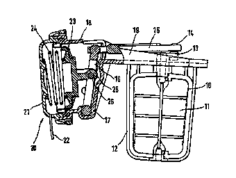
The sectional representation according to Figure 1 shows a passage 10 carrying
aspirated air, which is closed by a pivotable flap 11. The pivotable flap 11
is
journaled at both ends in a housing 12 and has a lever 13 at the upper journal
location. This lever 13 is connected via a ball joint 14 to a traverse rod 15.
The
traverse rod is in contact on the end opposite the ball joint 14 with a
coupling rod 16.
The coupling rod 16 is mounted for rotation in a bearing socket 17. An
actuator
housing 18, which is connected by the flange 19 to the housing 12, carries a
vacuum
box 20. This vacuum box has a housing cover 21 with a connection 22 for a
vacuum
hose, not shown here. In the housing cover 21 there is a resiliently mounted
diaphragm 23 which is supported against a pressure spring 24. The diaphragm is
equipped with a joint hook 25 which encloses a mounting pin 26 on the coupling
rod
16. In the position of the pivotable flap 11 shown here, the diaphragm 23 is
in the
rest position, and no vacuum is applied.
Figure 2 shows the device for shifting the position of a valve flap in the
open
position. The pivotable flap11 is rotated by 90° as a result of a
vacuum applied to
the connection 22. The vacuum produces an axial movement of the diaphragm 23
against the force of the spring 24; this movement is transmitted through the
coupling
rod 16 and the traverse rod 15 to the pivotable flap 11.
Of course, intermediate positions are also possible. The position of the
pivotable
flap 11 is dependent on the applied vacuum. Usually, however, the valve flap
is
operated only between the two positions, closed and open.
Figure 3 shows the operation of an asymmetrical vacuum box which is connected
to

CA 02297227 2000-O1-11
4
the position adjusting mechanism of the throttle valves. The heart of the
asymmetrical vacuum box 20 is the hook plate 30 which is connected to the
diaphragm 31 and at the same time carries a pivot point 29. It thus combines
the
functions of a diaphragm disk 27 and coupling rod 16 (Figure 1 ). The hook
plate is
journaled on at least one ball joint 28 in the housing of the vacuum box. The
pivot
point 29 of hook plate 30, connected to the traverse rod 15, therefore
performs a
circular movement when the vacuum box is actuated. The throttle valve 11 is
thus
shifted in position in the same manner as in the embodiment described in
Figure 1.
As an alternative to the jointed pivot point 29, a rigid connection can also
be
provided between the traverse rod and hook plate. In this version the ball
joint 28 is
omitted, and the hook plate 30 executes a substantially translational
movement. The
vacuum box is operated by a vacuum which can be applied to a vacuum connection
22 and which acts against a spring 24.
Figure 3 shows a plan view of the vacuum box with the housing cover 21
removed,
viewed from the direction A (see Figure 2). The hook plate is shown in broken
lines.
The external contour 34 and the spring socket 33 can be seen. The housing wall
35
of the vacuum box receives the sealing bead 36 of the diaphragm 31.

Representative Drawing
A single figure which represents the drawing illustrating the invention.
Administrative Status

2024-08-01:As part of the Next Generation Patents (NGP) transition, the Canadian Patents Database (CPD) now contains a more detailed Event History, which replicates the Event Log of our new back-office solution.

Please note that "Inactive:" events refers to events no longer in use in our new back-office solution.

For a clearer understanding of the status of the application/patent presented on this page, the site Disclaimer , as well as the definitions for Patent , Event History , Maintenance Fee  and Payment History  should be consulted.

Event History

Description Date
Application Not Reinstated by Deadline 2003-06-25
Time Limit for Reversal Expired 2003-06-25
Deemed Abandoned - Failure to Respond to Maintenance Fee Notice 2002-06-25
Letter Sent 2000-05-17
Inactive: Single transfer 2000-04-20
Inactive: Cover page published 2000-03-21
Inactive: First IPC assigned 2000-03-17
Inactive: Courtesy letter - Evidence 2000-03-07
Inactive: Notice - National entry - No RFE 2000-03-02
Inactive: Inventor deleted 2000-03-02
Application Received - PCT 2000-02-28
Application Published (Open to Public Inspection) 1999-01-21

Abandonment History

Abandonment Date Reason Reinstatement Date
2002-06-25

Maintenance Fee

The last payment was received on 2001-05-17

Note : If the full payment has not been received on or before the date indicated, a further fee may be required which may be one of the following

  • the reinstatement fee;
  • the late payment fee; or
  • additional fee to reverse deemed expiry.

Patent fees are adjusted on the 1st of January every year. The amounts above are the current amounts if received by December 31 of the current year.
Please refer to the CIPO Patent Fees web page to see all current fee amounts.

Fee History

Fee Type Anniversary Year Due Date Paid Date
Basic national fee - standard 2000-01-11
Registration of a document 2000-04-20
MF (application, 2nd anniv.) - standard 02 2000-06-27 2000-06-14
MF (application, 3rd anniv.) - standard 03 2001-06-25 2001-05-17
Owners on Record

Note: Records showing the ownership history in alphabetical order.

Current Owners on Record
FILTERWERK MANN & HUMMEL GMBH
Past Owners on Record
ARTHUR KLOTZ
GEORG MEHNE
THOMAS JESSBERGER
Past Owners that do not appear in the "Owners on Record" listing will appear in other documentation within the application.
Documents

To view selected files, please enter reCAPTCHA code :


To view images, click a link in the Document Description column (Temporarily unavailable). To download the documents, select one or more checkboxes in the first column and then click the "Download Selected in PDF format (Zip Archive)" or the "Download Selected as Single PDF" button.

List of published and non-published patent-specific documents on the CPD .

If you have any difficulty accessing content, you can call the Client Service Centre at 1-866-997-1936 or send them an e-mail at CIPO Client Service Centre.

({010=All Documents, 020=As Filed, 030=As Open to Public Inspection, 040=At Issuance, 050=Examination, 060=Incoming Correspondence, 070=Miscellaneous, 080=Outgoing Correspondence, 090=Payment})


Document
Description 
Date
(yyyy-mm-dd) 
Number of pages   Size of Image (KB) 
Representative drawing 2000-03-20 1 11
Description 2000-01-10 4 167
Abstract 2000-01-10 1 64
Claims 2000-01-10 2 50
Drawings 2000-01-10 2 68
Reminder of maintenance fee due 2000-02-28 1 113
Notice of National Entry 2000-03-01 1 195
Courtesy - Certificate of registration (related document(s)) 2000-05-16 1 113
Courtesy - Abandonment Letter (Maintenance Fee) 2002-07-22 1 183
Reminder - Request for Examination 2003-02-24 1 120
Correspondence 2000-03-01 1 14
PCT 2000-01-10 11 372