Language selection

Search

Patent 2297388 Summary

Third-party information liability

Some of the information on this Web page has been provided by external sources. The Government of Canada is not responsible for the accuracy, reliability or currency of the information supplied by external sources. Users wishing to rely upon this information should consult directly with the source of the information. Content provided by external sources is not subject to official languages, privacy and accessibility requirements.

Claims and Abstract availability

Any discrepancies in the text and image of the Claims and Abstract are due to differing posting times. Text of the Claims and Abstract are posted:

  • At the time the application is open to public inspection;
  • At the time of issue of the patent (grant).
(12) Patent Application: (11) CA 2297388
(54) English Title: ROOF DRAIN COVER
(54) French Title: COUVRE-DRAIN DE TOITURE
Status: Deemed Abandoned and Beyond the Period of Reinstatement - Pending Response to Notice of Disregarded Communication
Bibliographic Data
(51) International Patent Classification (IPC):
  • E04D 13/04 (2006.01)
(72) Inventors :
  • CORMIER, JACQUES (Canada)
(73) Owners :
  • JACQUES CORMIER
(71) Applicants :
  • JACQUES CORMIER (Canada)
(74) Agent:
(74) Associate agent:
(45) Issued:
(22) Filed Date: 2000-01-26
(41) Open to Public Inspection: 2000-07-27
Availability of licence: N/A
Dedicated to the Public: N/A
(25) Language of filing: English

Patent Cooperation Treaty (PCT): No

(30) Application Priority Data:
Application No. Country/Territory Date
60/117,590 (United States of America) 1999-01-27

Abstracts

English Abstract


The roof drain cover of the present invention comprises a
dome-shaped strainer adapted to sit over a roof drain pipe, a bolt going
through the
strainer at the centre thereof, protruding from the same to downwardly extend
within the pipe and having a bolt head accessible from above the strainer and
abutting the same, an anchor and a disc-like stop. The anchor includes a nut
screwed on the bolt, a pair of wings pivoted on the nut and foldable along the
bolt
and towards the strainer against the bias of a spring carried by the nut. The
tips
of the wings are adapted to frictionally engage the inner face of the pipe
under
the bias of the spring to prevent rotation of the nut when the bolt is screwed
within the strainer. The disc-like stop is secured to the bolt above the nut
and
engages the wings to cause firm anchoring engagement of the wing tips with the
pipe when the stop approaches the nut during screwing of the bolt.


Claims

Note: Claims are shown in the official language in which they were submitted.

CLAIMS
The embodiments of the invention, in which an exclusive property or
privilege is claimed, are defined as follows:
1. A roof drain cover comprising a dome-shaped strainer adapted
to sit over a roof drain pipe, a bolt going through said strainer at the
centre
thereof, protruding from the same to downwardly extend within said pipe and
having a bolt head accessible from above said strainer and abutting the same,
an
anchor including a nut screwed on said bolt, a pair of wings pivoted on said
nut
and foldable along said bolt and towards said strainer against the bias of a
spring
carried by said nut, the tips of said wings being adapted to frictionally
engage the
inner face of said pipe under the bias of said spring to prevent rotation of
said nut
when said bolt is screwed within said strainer, and a disc-like stop secured
to
said bolt above said nut, engaging said wings and causing firm anchoring
engagement of said wing tips with the pipe when said stop approaches said nut
during screwing of said bolt.
2. A roof drain cover as defined in claim 1, further including a strip
located in said strainer, secured to said side wall under said top wall, said
bolt
going through said strip and having a bolt head located between said top wall
and
said strip and abutting the latter.
3. A roof drain cover as defined in claim 2, wherein said strip
extends diametrically across said strainer.
5

4. A roof drain cover as defined in claim 1, further including a cap
covering each of said wing tips, said caps being adapted to frictionally
engage
the inner face of said pipe under the bias of said spring to prevent rotation
of said
nut when said bolt is screwed within said strainer.
5. A roof drain cover as defined in claim 2, further including a cap
covering each of said wing tips, said caps being adapted to frictionally
engage
the inner face of said pipe under the bias of said spring to prevent rotation
of said
nut when said bolt is screwed within said strip.
6

Description

Note: Descriptions are shown in the official language in which they were submitted.


CA 02297388 2000-O1-26
TITLE OF THE INVENTION
Roof drain cover.
FIELD OF THE INVENTION
The present invention relates to a system for anchoring a roof drain
strainer in position sitting over a roof drain pipe.
BACKGROUND OF THE INVENTION
Many roof drain covers are used to retain undesirable large debris
such as leaves or the like from going into the drain pipe and possibly
blocking the
same by forming an obstruction wall while allowing for rain water for passing
therethrough to be drained. Most of these covers are either simply inserted
into
the drain pipe opening without being really secured thereto or removably
secured
thereto. The secured covers generally require a collar or adapter that is
itself
secured to the drain pipe opening; such as in US Patents 4,487,690 and
4,961,848 to Logsdon, 4,505,814 to Marshall, 5,526,613 to Simeone, Jr.,
5,618,416 to Haefner and 5,724,777 to Hubbard. Other roof drain covers such as
in US Patent 5,234,582 to Savoie are provided with legs (30, 32, 52 and 54)
that
frictionally engage the inside surface of the drain pipe (14) under a force
exerted
by a screw (42, 44). A plurality of these screws are required added to the
fact
that they are located in close proximity of the roof surface which is not
always
convenient, especially when the roof drain is recessed from that roof surface.
OBJECTS OF THE INVENTION
The general object of the present invention is to provide a roof drain
cover that obviates the above noted disadvantages.
1

CA 02297388 2000-O1-26
Another object of the present invention is to provide a roof drain
cover that is of simple, inexpensive and yet long-lasting construction and can
easily be installed and removed.
A further object of the present invention is to provide a roof drain
cover that is adapted to be installed in roof-drain pipe of different opening
diameters.
SUMMARY OF THE INVENTION
The roof drain cover of the present invention comprises a dome-
shaped strainer adapted to sit over a roof drain pipe, a bolt going through
said
strainer at the centre thereof, protruding from the same to downwardly extend
within said pipe and having a bolt head accessible from above said strainer
and
abutting the same, an anchor including a nut screwed on said bolt, a pair of
wings
pivoted on said nut and foldable along said bolt and towards said strainer
against
the bias of a spring carried by said nut, the tips of said wings being adapted
to
frictionally engage the inner face of said pipe under the bias of said spring
to
prevent rotation of said nut when said bolt is screwed within said strainer,
and a
disc-like stop secured to said bolt above said nut, engaging said wings and
causing firm anchoring engagement of said wing tips with the pipe when said
stop approaches said nut during screwing of said bolt.
Preferably, the cover further includes a strip located in said strainer,
secured to said side wall under said top wall, said bolt going through said
strip
and having a bolt head located between said top wall and said strip and
abutting
the latter. Preferably, the strip extends diametrically across said strainer.
Preferably, the cover further includes a cap covering each of said
wing tips, said caps being adapted to frictionally engage the inner face of
said
2

CA 02297388 2000-O1-26
pipe under the bias of said spring to prevent rotation of said nut when said
bolt is
screwed within said strainer.
BRIEF DESCRIPTION OF THE DRAWINGS
In the annexed drawings, like reference characters indicate like
elements throughout.
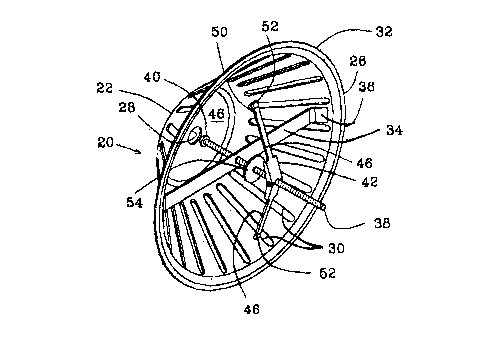
Figure 1 is a perspective section view of an embodiment of the
strainer of the present invention installed on the roof drain pipe opening;
Figure 2 is bottom perspective view of the embodiment of Fig. 1;
Figure 3 is a vertical view of the embodiment of Fig. 1;
Figure 4 is an exploded top perspective view of the embodiment of
Fig. 1; and
Figure 5 is an enlarged perspective view of the section wing of the
embodiment of Fig. 1.
DETAILED DESCRIPTION OF THE PREFERRED EMBODIMENT
As shown in Figs. 1 and 2, the roof drain cover 20 of the invention is
of a dome-shaped strainer 22 that has as a top wall 24 and a downwardly
flaring
side wall 26. The top wall 24 has a central hole 28. Side walls 26 are
provided
with the usual draining slots 30; the lower edge 32 of strainer 22 is adapted
to sit
over the roof membrane M in register with a drain pipe P. A cross-strip 34
extends diametrically across the strainer 22 with its outer ends 36 secured to
the
side wall 26. A bolt 38 downwardly extends centrally of the strainer 22 and
goes
through strip 34. The bolt head 40 of bolt 38 abuts the strip 34 and is
accessible
through central hole 28. A spring wing 42 is carried by bolt 28, more
specifically
the nut 44 of spring wing 42 is screwed on the bolt 38 below strip 34 and
wings
46 are pivoted to the nut 44 for foldable movement towards bolt 38 against the
3

CA 02297388 2000-O1-26
bias of a spring 48 carried by the nut 44 (see Figs. 4 and 5). As shown in
Fig. 3,
the wing tips 50 are preferably covered with rubber caps 52 adapted to
frictionally
engage the inner surface of the pipe P sufficiently to prevent rotation of
spring
wing 42 when bolt 38 is rotated. Arrows A indicate the action of the spring 48
on
wings 46. A disc-shaped stop 54 is fixed to bolt 38 just above nut 44 and
presses
down the tip 50 of the wings 46 and its cap 52 when bolt 38 is screwed, with
its
head 40 abutting the strip 34, by a screwdriver S inserted through central
hole 28
and engaging bolt head 40. The stop 54 forces wings 46 and their caps 52 into
positive engagement with the pipe P in accordance with arrows B & A. Bolt 38
with spring wing 42 constitute an anchor for strainer 22. To remove strainer
22,
bolt 38 is completely unscrewed from spring wing 42 and the latter is
withdrawn
from pipe after removal of strainer 22.
Preferably, to have a long-lasting construction characteristic, the
dome-shaped cover and the cross-strip of the strainer are made out of
corrosion
free material such as stainless steel, aluminum or proper thermoplastic.
Although an embodiment has been described herein with some
particularity and details, many modifications and variations of the preferred
embodiment are possible without deviating from the scope of the present
invention.
4

Representative Drawing
A single figure which represents the drawing illustrating the invention.
Administrative Status

2024-08-01:As part of the Next Generation Patents (NGP) transition, the Canadian Patents Database (CPD) now contains a more detailed Event History, which replicates the Event Log of our new back-office solution.

Please note that "Inactive:" events refers to events no longer in use in our new back-office solution.

For a clearer understanding of the status of the application/patent presented on this page, the site Disclaimer , as well as the definitions for Patent , Event History , Maintenance Fee  and Payment History  should be consulted.

Event History

Description Date
Application Not Reinstated by Deadline 2006-01-26
Time Limit for Reversal Expired 2006-01-26
Inactive: Office letter 2005-11-29
Change of Address Requirements Determined Compliant 2005-11-29
Change of Address or Method of Correspondence Request Received 2005-11-16
Inactive: Adhoc Request Documented 2005-10-31
Inactive: Abandon-RFE+Late fee unpaid-Correspondence sent 2005-01-26
Deemed Abandoned - Failure to Respond to Maintenance Fee Notice 2005-01-26
Inactive: Office letter 2003-03-19
Revocation of Agent Requirements Determined Compliant 2003-03-19
Revocation of Agent Request 2003-02-28
Application Published (Open to Public Inspection) 2000-07-27
Inactive: Cover page published 2000-07-26
Inactive: Office letter 2000-07-12
Revocation of Agent Requirements Determined Compliant 2000-07-12
Revocation of Agent Request 2000-06-15
Inactive: First IPC assigned 2000-03-15
Inactive: Office letter 2000-03-01
Inactive: Filing certificate - No RFE (English) 2000-02-29
Filing Requirements Determined Compliant 2000-02-29
Application Received - Regular National 2000-02-29

Abandonment History

Abandonment Date Reason Reinstatement Date
2005-01-26

Maintenance Fee

The last payment was received on 2003-10-10

Note : If the full payment has not been received on or before the date indicated, a further fee may be required which may be one of the following

  • the reinstatement fee;
  • the late payment fee; or
  • additional fee to reverse deemed expiry.

Please refer to the CIPO Patent Fees web page to see all current fee amounts.

Fee History

Fee Type Anniversary Year Due Date Paid Date
Application fee - small 2000-01-26
MF (application, 2nd anniv.) - small 02 2002-01-28 2002-01-16
MF (application, 3rd anniv.) - small 03 2003-01-27 2002-12-19
MF (application, 4th anniv.) - small 04 2004-01-26 2003-10-10
Owners on Record

Note: Records showing the ownership history in alphabetical order.

Current Owners on Record
JACQUES CORMIER
Past Owners on Record
None
Past Owners that do not appear in the "Owners on Record" listing will appear in other documentation within the application.
Documents

To view selected files, please enter reCAPTCHA code :


To view images, click a link in the Document Description column. To download the documents, select one or more checkboxes in the first column and then click the "Download Selected in PDF format (Zip Archive)" or the "Download Selected as Single PDF" button.

List of published and non-published patent-specific documents on the CPD .

If you have any difficulty accessing content, you can call the Client Service Centre at 1-866-997-1936 or send them an e-mail at CIPO Client Service Centre.


Document
Description 
Date
(yyyy-mm-dd) 
Number of pages   Size of Image (KB) 
Representative drawing 2000-07-13 1 16
Description 2000-01-26 4 155
Abstract 2000-01-26 1 25
Claims 2000-01-26 2 50
Drawings 2000-01-26 3 78
Cover Page 2000-07-13 1 44
Filing Certificate (English) 2000-02-29 1 164
Reminder of maintenance fee due 2001-09-27 1 116
Notice: Maintenance Fee Reminder 2003-10-28 1 114
Reminder - Request for Examination 2004-09-28 1 121
Notice: Maintenance Fee Reminder 2004-10-27 1 119
Courtesy - Abandonment Letter (Request for Examination) 2005-04-06 1 166
Courtesy - Abandonment Letter (Maintenance Fee) 2005-03-23 1 174
Second Notice: Maintenance Fee Reminder 2005-07-27 1 116
Notice: Maintenance Fee Reminder 2005-10-27 1 118
Correspondence 2000-03-01 1 6
Correspondence 2000-06-15 2 46
Correspondence 2000-07-12 1 9
Correspondence 2000-07-12 1 8
Fees 2002-12-19 1 22
Correspondence 2003-02-28 1 30
Correspondence 2003-03-19 1 13
Correspondence 2003-03-19 1 17
Fees 2003-10-10 1 23
Fees 2002-01-16 1 26
Correspondence 2005-11-16 1 26
Correspondence 2005-11-29 1 24