Note: Descriptions are shown in the official language in which they were submitted.
CA 02297856 2004-04-02
r
INK CUPS FOR PAD PRINTING MACHINES
Field of The Invention
The present invention is directed to improved ink cups used in pad printing
machines.
Back~~round of The Invention
Seated ink cup pad printing machines comprise an ink cup which is supported
in inverted fashion with a sealing and doctoring end surface thereof in
abutment with a
printing block or "cliche" that is mounted in reciprocating fashion for
transferring ink in a
predetermined pattern to a printing pad. The ink cup includes an annular
surface, which
may be an integral part of the cup or, alternatively, a separate ring, that
serves as a sliding
seal between the ink cup and the cliche and as a doctor blade or "knife" for
ensuring that
only the engraved portions of the cliche carry ink to the printing pad pick-up
site.
U.S. Patent Nos. 4,557,195 and 4,905,594 disclose examples of prior such
machines and their disclosures may be referred to for further details.
To ensure quality printing with pad printers, it is important that the annular
doctor blade of the ink cup reliably scrape or wipe from the cliche plate all
ink that is not
within the engraving recesses. Consistently obtaining the clean wiping action
has
presented problems. To obtain and maintain a sealing and wiping action, doctor
elements
typically have been formed of a very hard material, such as carbide, ceramic,
high speed
steel, or other hard metal and have been finished to a very accurate planar
surface, as by
lapping. For example, the aforenoted U.S. Patent No. 4,557,195 describes the
use of hard
materials for forming the end contact surfaces of the ink cups, at least in
those areas which
serve a wiping function. A further suggestion is made therein that it may be
possible to
use elastic parts made of metal or plastic for the side portions of
rectangular cup end
surfaces which extend parallel to the direction of displacement and do not
have a wiping
function, but merely serve the function of sealing aprons in a non-etched
area.
Many cliches are made of metal, particularly for high volume reproduction of
the same image. However, cliches which have a plastic gravure surface, e.g. of
a
photosensitive polymer material, have gained wide usage because generally they
are much
less expensive to produce and to engrave than the cliches which use a metal
gravure
1
CA 02297856 2004-04-02
surface. The plastic gravure surfaces may be provided by using a basic support
plate or
block, as of metal, with a gravure surface formed by a layer, laminate or
coating of a
photosensitive polymer, or may constitute an entire plate or block of such a
polymer
material. However, the plastic gravure surfaces have tended to wear much more
rapidly
than the metal or metal-surfaced cliches. For this reason, the cliches with
plastic gravure
surfaces have been used primarily for relatively short production runs.
Ink cups have generally been formed of metals such as aluminum, steel, or
plastics. The doctoring portion of the cup is ordinarily constructed of
carbide steel. U.S.
Patent No. 5,662,041 discloses an ink cup wherein the doctoring portion is
formed of a
polymeric material, such as a polymeric composite containing
polyaryletherketone and
carbon fibers, permeated by a solid lubricant.
The ink cup, the doctoring portion and by extension, the materials) of which
it
is constructed, must exhibit certain physical properties. They must be
chemically resistant
to components of the ink, notably dibasic esters and aromatic hydrocarbons.
They must
also be sufficiently strong and stiff in view of the demanding operating
environment.
Furthermore, the materials used to construct the doctoring portion must be
resistant to
wear, as the doctoring portion repeatedly wipes the cliche during operation.
Summary of the Invention
Accordingly, this invention seeks to provide an improved ink cup for pad
printing machines that is formed of plastic materials.
Further, the invention seeks to provide an ink cup wherein the doctoring
portion of the ink cup is formed of plastic material.
Still further, the invention seeks to provide a doctoring blade formed of a
plastic material which provides the chemical resistance necessary to withstand
the adverse
effects of exposure to dibasic esters and aromatic hydrocarbons found present
in the inks.
Yet further, the invention seeks to provide a doctoring blade formed of a
plastic material which is sufficiently stiff and strong so as to withstand the
conditions of
the operating environment.
Further still, the invention seeks to provide a doctoring blade formed of a
2
CA 02297856 2004-04-02
plastic material which is sufficiently resistant to wear.
It has been found that the doctoring portion of an ink cup of a pad printing
device, can be formed of plastic materials which exhibit the required chemical
resistance
and stiffness, at a significant cost savings, when compared to cups having
metal doctoring
portions. That is, the carbide steel ring that is primarily used as the
doctoring portion of
the cup is very expensive and in fact accounts for most of the costs of
construction.
Accordingly, an ink cup having a plastic doctoring portion, available at a
reduced cost,
capable of operating in the same environment as an ink cup with a metal
doctoring
portion, offers a significant advantage over the prior art cups.
When a plastic doctoring portion is used, the molten plastic material fills
the
space where the carbide steel ring would otherwise be inserted into the ink
cup. Thus, in
any polymeric material that is to be used as the doctoring portion must be
injection
moldable and machinable to tight tolerances.
The doctoring portion preferably is formed of a polymeric composite which has
1 S high compressive strength and high resistance to chemicals, notably to
printing inks. The
polymeric doctoring portion should define a narrow distal end surface which
circumscribes
the open end of the cup for compressive sliding, sealing and doctoring
engagement with
an opposed plastic gravure surface. The doctoring portion may be a separate
ring element
suitably mounted at the open end of the cup body or it may be a unitary part
of the cup.
It has been found that some wear of the distal end occurs and that the
reliability of
obtaining clean doctoring of the gravure surface decreases significantly in
current
machines when the tip width increases beyond about 0.03 inches. It is
beneficial to form
this contact portion with a narrow tapered cross section, such as, merely for
exemplary
purposes, with an initial tip width on the order of 0.015 inches and tapering
to
approximately 0.021 inches within the range of anticipated wear.
A specific material which is preferred for forming the doctoring portion is a
polymer composite of a 65% mineral and glass loaded polyphenylene sulfide,
available
from the GE Plastics, Pittsfield MA., under the tradename SUPEC 6323. Other
suitable
materials for the plastic cup include a 60% ceramic loaded nylon 6,6,
(available from LNP
Engineering Plastics, Inc., Exton, PA., under the designation LSG440), filled
3
CA 02297856 2004-04-02
s
polyamides such as PA 6 or PA 6,6, or other polyamides, filled polyesters,
such as
polyethylene terephthalate) or poly(butylene terephthalate), filled or
unfilled
polyetherketone (PEEK), filled acetal, filled or unfilled polyphenylene oxide,
filled or
unfilled polyarylimide (PAI), filled or unfilled polyethersulfone (PES) and
thermoset
materials, such as phenolics or polyesters. These polymers may or may not
contain fillers.
Suitable fillers include glass, mineral, carbon fiber, wollastonite, mica and
platy talc.
BRIEF DESCRIPTION OF THE DRAWINGS
FIG. 1 is a side view of the printer section of a pad printing machine.
FIG. 2 is a vertical view, partially in section, taken generally along the
broken
line 2 - 2 of FIG. 1.
FIG. 3 is a view of the apparatus of FIG. 1 with the cliche and the printing
pad
advanced to their impression transferring positions.
FIG. 4 is an enlarged diametrical cross sectional view of an ink cup and
abutting cliche as in FIG. 2.
FIG. 5 is an enlarged perspective view of a doctor ring as in FIG. 4.
FIG. 6 is a view similar to FIG. 4 illustrating another embodiment employing
teachings of this invention, namely in an ink cup wherein the doctor ring
portion is formed
integral with the main body of the cup.
FIG. 7 is a cross-sectional view of an alternative embodiment of the present
invention.
DESCRIPTION OF THE PREFERRED EMBODIMENTS
The drawings illustrate the ink holding and transfer components of a pad type
printing machine 10. The machine includes a support frame of which the
illustrated
portions include a base 12 and an upper frame portion 14 both of which are
components
of an appropriate frame structure for such machines, as is known in this art.
A flat
4
CA 02297856 2004-04-02
gravure plate 16 is suitably mounted on the plate bed for reciprocation
between a retracted
inking position as in FIG. 1 and an extended transfer position as seen in FIG.
3. This
plate 16, also commonly known as a cliche, may be of any suitable material,
typically
being metal, plastic or a combination thereof and normally being photo
engraved on its
upper gravure surface 17 with the text, logo or other pattern which is to be
printed by the
operation of the machine 10. In the machine 10 the gravure surface 17 is the
upper
surface of a non-metallic, preferably plastic layer 16A which carries the
engraved image in
a known manner, see FIG. 4. Preferably, this is a thin layer of a
photoreactive polymer
which is applied to the top surface of a printing block body 16B of another
material, such
as by affixation of a sheet or coating 16A of the photosensitive polymer to a
base printing
block 16B formed of metal or the like. However, the gravure surface 17 also
may be an
integral part of a printing block formed of an appropriate polymer material.
Suitable polymer gravure materials and commercial products for providing the
plastic gravure surface 1? are known. For example, they include plates and
laminates made
of the various so called photosensitive or photoreactive polymers currently
available in the
market, such as various polyamide photopolymer materials. Further, they may be
of the
water wash types, such as the "nyloprint" and "nylograv" plates available from
BASF
Lacke + Farben AG of Stuttgart, Germany, or alcohol wash types, such as of the
"ST-52"
material available from the same company.
A transfer pad 18 of appropriate configuration is mounted on a support rod 20
for suitable vertical reciprocating motion. With the cliche or plate 16
extended, the pad 18
is pressed against the engraved area of the cliche as in FIG. 3 to receive the
ink pattern
therefrom and then is retracted upward. While the cliche 16 subsequently is
retracted as
in FIG. 1 for re-inking, the pad 18 is advanced against a recipient object to
transfer the ink
pattern thereto, in a known manner by any appropriate coordinated driving
mechanism.
An ink cup 22 is mounted over the cliche 16 to serve as a supply reservoir
for the printing ink. The cup has an open bottom for free access of the ink to
the
upper surface 17 of the cliche 16 and has a doctor blade or "knife" ring
portion 24
around its open lower end. This blade 24 must be maintained in continuous and
constant contact with the adjacent surface 17 of the cliche 16 at all times to
form a
seal for retaining the ink supply in the cup 22 and to scrape the surface 17
clean of all
ink thereon as the cliche 16 is advanced from the loading position of FIG.
5
CA 02297856 2000-O1-31
i to the transfer position of FIG. 3, except only for the ink in the
depressions engraved or
otherwise formed in the upper surface 17 to define the print pattern. The
blade portion 24 may
be part of the cup itself or a separate element suitably attached to the lower
end of the cup. In
either event, the doctor blade presents a very narrow distal end surface 25
against the cliche
and is subject to continual wiping action against the cliche as the cliche is
reciprocated. The
blade ring 24 is formed of a plastic which has high compressive strength,
thereby providing a
firm lower doctoring edge portion of plastic. The~lade ring must also exhibit
suitable chemical
resistance to the ingredients of the ink, such as dibasic esters.
The contact end surface 25 of the knife ring and the upper surface 17 of the
cliche
should be accurately formed and maintained in suitable compressive abutting
engagement with
one another throughout the length of the knife blade, i.e. throughout the
circumference of the
ring. Slight deviations of either surface from the other, on the order of a
few microns, or even
variations in the compressive force between the two surfaces along different
portions of the
circumference of the ring, can cause leakage of the ink, or leave a film of
ink in undesired
areas of the exposed portions of the cliche (sometimes referred to as
"fogging") and/or cause
scratches or other undesirable wear patterns on the cliche and/or the doctor
ring which can
adversely affect the useful life of the relatively expensive cliches and
rings. Thus, it is highly
desirable that intimate but uniform pressure contact be maintained between the
ring and the
gravure surface of the cliche.
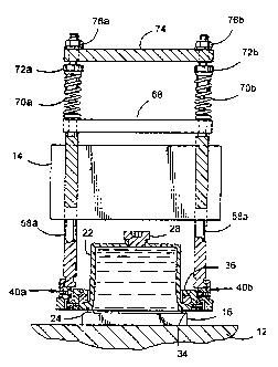
An adjustment handle 26 is provided at the front ofthe apparatus to adjust the
effective length of the support rod. A removable filler plug 28 is provided in
the upper end of
the ink cup. The cup 22 also includes an annular flange 34, such as is
typically provided
adjacent the lower open end of such cups.
The hold down mechanism for maintaining the cup in position with its doctor
blade 24
in desirable continuous engagement with the cliche 16 includes: A thrust
collar 36 which fits in
superposed relationship over the flange 34; the collar 36 is pivotably mounted
at diametrically
opposite sides by a pair of interconnection mechanisms 40a and 40b for pivotal
movement
about an axis "X" which is parallel to the surface 17 and perpendicular to the
reciprocating
path of the cliche; and, the bearing structure for applying external downward
forces to the
thrust collar 36 and thus to the cup 22 is of a design to assure that these
forces are applied to
the collar at points spaced forwardly and rearwardly of the transverse pivot
axis X (see FIG.
6
CA 02297856 2004-04-02
3) and not directly on the pivot axis, to provide a restraining or stiffening
action which
resists fore-and-aft tilting tendencies of the cup as the cliche reciprocates.
Down-pressure forces are applied to the cup support components by a pair of
pressure rods 58a, 58b which are disposed in parallel, upright arrangement
thereover.
Slight vertical relative movements are allowed between the two pressure rods
and hence
between the two sides of the collar 36 to allow tilting adjustment of the
collar and hence
of the cup 22 transversely of the center longitudinal horizontal axis which is
generally
parallel to the direction of reciprocation of the cliche and orthogonal to the
aforementioned
X axis. To this end the pressure rods 58a and 58b are mounted for vertical
movement in
the machine frame portion 14. A pressure plate 68 is mounted on the upper ends
of these
two rods 58a, 58b. A pair of compression springs 70a, 70b engage the upper
ends of the
respective rods 58a, 58b and have their upper ends confined by respective
adjustable
tension screw mechanisms 72a, 72b which are supported in an upper spring plate
74 that
is affixed to the machine frame 14. The compressive force applied by each
spring 70a,
70b can be adjusted, such as by threaded adjustment of the respective mounting
nuts
shown at 76a, 76b.
In the preferred embodiment, the cup 22 is formed of a hard plastic material
which provides suitable chemical resistance to withstand the ingredients of
the ink, such as
poly(butylene terephthalate), or any of the other materials described in this
patent
specification. The material could be the UHMW PE product TIVAR~ 1000. However,
the
benefits of this invention are realizable with ink cups formed of other
materials, such as
aluminum, steel or other metals.
Turning now particularly to FIGS. 4 - 6, the doctor ring portion 24 of the cup
22 is a separate continuous ring which is force-fit into a groove 42 in the
distal end face
43 of the cup body 44. As noted before, the ring includes a generally
rectangular base
portion 24 which fits into the groove 42 and a tapered end portion 25 which
narrows from
the base portion to a narrow distal edge or end surface 25 that constitutes
the doctoring
surface. The ring 24, when installed in the cup body 44 as in FIG. 4, defines
and
circumscribes the open end of the ink cup 22. The ring 24 is formed of a
polymeric
composite which has high compressive strength, e.g. greater than about 30,000
psi at
temperatures below about 300°F and up to about 21,750 psi below
100°F, i.e. at ambient
room temperatures. The polymeric composite also has high chemical resistance
to printing
inks, while also having good wear resistance, while continually renewing
7
CA 02297856 2000-O1-31
its surface. In one instance, the inventors found hat the tip width degraded
only slightly, from
an initial width of 0.015" to 0.021 ". That is, the distal doctoring end
surface is slow to wear
away while serving the doctoring function against an abutting and
reciprocating plastic
gravure surface, while the edge surface of the blade renews itself
continually. It appears that
the provision of a narrow end surface is important to obtaining clean
consistent wiping or
"doctoring" to remove from the surface 17 all ink except that which is in the
engraved grooves
which define the desired print pattern, with the down-forces normally applied
to the cups 22 in
the described types of machines.
FIG. 6 illustrates an alternative embodiment of an ink cup 22A in which a
doctoring
ring portion 24A is integral with the cup body 44A. Such a cup may be provided
by molding
the cup and ring as one unitary structure or by machining to its final form
from a moped or
cast blank of appropriate materials as described in this patent specification
with respect to the
ring portion 24. Alternatively, an integral unit 24A could be fabricated by
fusion molding or
"welding", using such materials for the doctor ring portion and a dif~'erent
but compatible
I S material for the cup body portion.
The doctoring portion 24 may be fabricated of a polymer composite of a 65%
mineral
and glass loaded polyphenylene sulfide, available from the GE Plastics,
Pittsfield MA., under
the tradename SUPEC 6323. Other suitable materials include a 60% ceramic
loaded nylon
6,6, (available from LNP Engineering Plastics, Inc. Exton PA., under the
designation
LSG440), filled polyamides, such as PA 6 or PA 6,6, or other polyamides,
filled polyesters,
such as polyethylene terephthalate) or poly(butylene terephthalate), filled or
unfilled
polyetherketone (PEEK), filled acetal, filled or unfilled polyphenylene oxide,
filled or unfilled
polyarylimide (PAI), filled or unfilled polyethersulfone (PES) and thermoset
materials, such as
phenolic or polyesters. These polymers may or may not contain fillers.
Suitable fillers include
glass, mineral, carbon fiber, wollastonite, mica, and platy talc. Depending on
the polymeric
material that is used, the filler may actually provide reinforcement,
improving the strength of
the composite relative to the polymer material when it does not contain the
reinforcing
material.
As one particular example, circular rings 24 have been machined from cylinders
of the
aforenoted material. Such rings had an outside diameter of 65 mm and an inside
diameter of
60 mm, resulting in a ring width (measured radially of the ring) of 2.5 mm
across the base
8
CA 02297856 2004-04-02
portion 24, a total axial depth of the ring of about 6 mm, a depth of the
rectangular base
24 of about 2 mm, a depth of the tapered portion 46 of about 4 mm and an
initial radial
width of the end surface 25 of about 0.05 mm. These rings have functioned very
well
until the width of the contact surface increased to the point that "fogging"
began to appear
on the gravure surface, apparently due to hydroplaning rather than clean
wiping
engagement by the end surface. With these particular rings, operated with
downpressure
forces typical for such machines, such fogging tended to occur when the end
surface 25
wore to a radial width of about 0.6 mm, having an initial width of 0.3 mm.
The initial sealing and wiping action of doctoring portions as described
herein
improve during initial use, apparently due to a self lapping action against
the abutting and
reciprocating plastic gravure surface. It has been found that rotating the cup
22
periodically to vary its rotational position relative to the direction of
reciprocation of the
cliche, e.g. following each few thousand print cycles, helps assure uniform
wear of the
doctoring portion and the gravure surface while maintaining the sealing and
clean wiping
action on the gravure surface.
Rings as described herein have provided consistent clean doctoring operation
of
plastic gravure surfaces over greatly extended functional lives of the plastic
images, i.e.
providing substantial increases in the number of useful print cycles obtained
with each
plastic gravure plate as compared to use hard metal doctor rings on gravure
plates made of
the same plastic materials.
Figure 7 shows an alternative embodiment wherein the cliche drum 80 and
transfer pad 82 are of cylindrical shape. The ink reservoir 84 with lid 85 is
dimensioned
with an opening 86 into which the cliche drum is fitted against the edges 88
of the
opening. Doctor blades 90 having doctoring portions 92 are in abutment with
the cliche
drum 80 and the edges of the reservoir 88. The doctoring portions 92 are
tapered and
perform the doctoring function against the abutting and rotating transfer pad
82 having
gravure surface 94. The narrow end surface of the doctoring portions 92
provides a clean,
consistent wiping or doctoring which removes all ink from the surface of the
cliche drum
80 except that which is in the engraved grooves of the cliche drum 80.
9
CA 02297856 2000-O1-31
EXAMPLE
An ink cup and doctoring portion were molded out of a 65% mineral and glass
loaded
polyphenylene sulfide, available from the GE Plastics, Pittsfield MA., under
the tradename
SUI'EC 6323. During molding, the carbide steel doctoring portion insert was
not used. The
polymeric composite filled the space where the insert would have been, thereby
forming the
doctoring portion in the shape of a ring. The ring edge was then machine to
specific
dimensions.
The ink cup was tested for ink doctoring performance. It was found to deliver
ink to a
steel cliche for over 495,000 cycles. In addition the ink cup was tested to
see how it delivered
ink to a polymeric etched plate and was found to deliver for over 262,000
cycles before the
polymeric plate wore out. It was noted that in each instance, the ink cup
formed of the PPS
composite exhibited good chemical resistance to the components of pad printing
inks.