Note: Descriptions are shown in the official language in which they were submitted.
CA 02298040 2000-02-02
LOAD BEARING PIVOT ASSEMBLY PROVIDING A
FLUID PATH
BACKGROUND OF THE INVENTION
The present invention generally relates to
power machines such as front end loaders and skid steer
loaders. More specifically, the present invention
relates to a load bearing pivot assembly for connecting
a boom arm of a power machine to the main frame or an
implement (eg, adapter plate) or both.
Power machines, such as front end loaders and
skid steer loaders, typically have a main frame which
supports a cab or an operator compartment and a movable
boom arm which, in turn, supports an implement. The
implement is typically an adapter plate capable of
releasable connection to an attachment such as a bucket
or an attachment requiring pressurized hydraulic fluid
for operati--n such as an auger, a snowblower, a stump
grinder, a hydraulic breaker, or the like. The movable
boom arm is pivotally coupled to the main frame of the
power machine and is powered by power actuators which
are commonly hydraulic cylinders. In addition, the
attachment coupled to the implement (i.e. the adapter
plate) is typically powered by one or more additional
power actuators which are also commonly hydraulic
cylinders. An operator manipulating such a power
machine raises and lowers the boom arm, and manipulates
the attachment, by actuating the hydraulic cylinders
coupled to the boom arm, and the hydraulic cylinders
coupled to the attachment.
An attachment requiring pressurized hydraulic
fluid for operation typically receives the hydraulic
fluid through hydraulic lines or hoses. The hydraulic
lines are routed along the boom arm to the distal end of
the boom arm where a connection is made to the
CA 02298040 2000-02-02
-2-
attachment. Quick couplers may be mounted to the
hydraulic lines for quick connection to the attachment.
However, routing the pressurized hydraulic lines along
the boom arm to the attachment renders the hydraulic
lines susceptible to failure due to repeated flexure and
due to exposure to the surrounding abusive environment.
SUMMARY OF THE INVENTION
The present invention provides an improved
load bearing pivot assembly for connecting the boom arm
of a power machine such as a front end loader to the
main frame, or the implement (e.g., adapter plate) or
both. The load bearing pivot assembly provides a fluid
path therethrough in order to eliminate fluid lines at
the pivot point which are otherwise susceptible to
failure due to repeated flexure and due to being exposed
to an abusive environment.
In one embodiment of the present inventic n, a
power machine having a boom arm and an implement (e.g.,
an adapter plate) is provided with a load bearing pivot
assembly for pivotally connecting the implement to the
distal end of the boom arm. The pivot assembly includes
a two portions, one connected to the boom and the other
connected to the implement. Each portion has a fluid
path which are in fluid communication with each other.
The fluid paths eliminate the need for a fluid line
(e.g., a hose) at the pivot point which would otherwise
be exposed to continuous bending.
Both portions of the pivot assembly preferably
include a coupler for connection to a fluid line. One of
the fluid lines is connected to a source of pressurized
hydraulic fluid and the other line is adapted for
connection to an attachment requiring pressurized
hydraulic fluid for operation. Such attachments
include, but are not limited to, grapples, augers, tree
CA 02298040 2000-02-02
-3-
spades, jack hammers, etc. The fluid lines are
preferably at least partially contained within the boom
and/or the implement to protect the lines from exposure
to the abusive environment.
The fluid line that is adapted for connection
to an attachment may be connected to a movable (e.g.
slidable, rotatable) block mounted on the implement.
The movable block includes a coupler for releasable
connection to the attachment. With this arrangement, a
connection to the attachment may be accomplished :iy
maneuvering the implement and block with the loader
rather than by manually connecting the line to the
attachment.
One of the portions of the pivot assembly
preferably comprises a pin. The other portion of the
pivot assembly preferably comprises an annular bearing
surrounding the pin. The pin may include an annular
recess, a lateral channel and a longitudinal channel
which comprise a fluid path. The annular bearing may
include a gap which comprises another fluid path in
fluid communication with the fluid path of the pin. The
bearing preferably includes a bearing surface which is
lubricated by the fluids in the fluid paths.
In another embodiment of the present
invention, a power machine having two boom arms and an
implement (e.g., an adapter plate) is provided with two
load bearing pivot assemblies, one for pivotally
connecting each boom arm to the implement. Each pivot
assembly includes a fluid path therethrough. The fluid
paths eliminate the need for fluid lines (e.g., hoses)
at the pivot points which would otherwise be exposed to
continuous bending.
In yet another embodiment of the present
invention, a power machine having a main frame assembly
CA 02298040 2000-02-02
-4-
and a boom arm includes a load bearing pivot assembly
for pivotally connecting the main frame to the proximal
end of the boom arm. The pivot assembly includes a fluid
path defined therethrough. The pivot assembly
preferably includes a pin and an annular bearing
surrounding the pin. The pin may include an annular
recess, a lateral channel and a longitudinal channel
which comprise a fluid path. The annular bearing may
include a gap which comprises another fluid path in
fluid communication with the flui3 path of the pin. The
bearing preferably includes a bearing surface which is
lubricated by the fluid in the fluid paths.
BRIEF DESCRIPTION OF THE DRAWINGS
Figure 1 is a side view of a power machine, in
particular, a skid steer loader, as in the present
invention.
Figure 2 is a perspective view of an implement
in the form of an adapter as in the present invention.
Figure 3A is a rear view of an adapter
connected to a pair of boom arms by way of a load
bearing pivot assembly of the present invention.
Figure 3B is a rear view of a block assembly
movably mounted to an adapter as in the present
invention.
Figure 3C is a side view of the block assembly
illustrated in Figure 3B.
Figure 4 is a partially cross-sectioned detail
view of the load bearing pivot assembly illustrated in
Figure 3A.
DETAILED DESCRIPTION OF THE PREFERRED EMBODIMENTS
The following detailed description should be
read with reference to the drawings in which like
elements in different drawings are numbered the same.
The drawings, which are not necessarily to scale, depict
CA 02298040 2000-02-02
-5-
selected embodiments that illustrate the invention but
are not intended to limit the scope of the invention.
Those skilled in the art will recognize that many of the
examples provided have suitable alternatives which may
also be utilized without departing from the scope and
spirit of the invention.
Refer now to Figure 1 which illustrates a side
view of a power machine, specifically a skid steer
loader, of the present invention. Although the
following detailed description is focused on a skid
steer loader, those skilled in the art will recognize
that the essence of the present invention may be
implemented on a wide variety of power machines
including front end loaders and skid steer loader 10.
Skid steer loader 10 includes a frame 12
supported by wheels 14. Frame 12 also supports a cab 16
which defines an operator compartment and which
substantially encloses a seat 19 on which an operator
sits to control skid steer loader 10. A seat bar 21 is
pivotally coupled to a portion of cab 16. When the
operator occupies seat 19, the operator then pivots the
seat bar 21 from the raised position (shown in phantom
in Figure 1) to the lowered position shown in Figure 1.
A pair of boom arms or lift arms 17 are
coupled to frame 12 at pivot points 20 (only one of
which is shown in Figure 1, the other being identically
disposed on the opposite side of the loader 10) . A pair
of hydraulic cylinders (only one of which is shown in
Figure 1) are pivotally coupled to frame 12 at pivot
point 24 and are pivotally coupled to boom arms 17 at
pivot points 26. Boom arms 17 are also coupled to a
quick attachment adapter plate 40 which in turn is
connected to an attachment, such as a bucket and grapple
28 shown in phantom in Figure 1. Boom arms 17 are
CA 02298040 2000-02-02
pivotally coupled to the adapter plate 40 at pivot
points 30. In addition, a hydraulic cylinder 32 is
pivotally coupled to a cross member extending between
the boom arms 17 at pivot point 34 and to the adapter
plate 40 at pivot point 36. While one cylinder 32 is
shown, it is to be understood that two cylinders could
be used to manipulate the adapter plate 40.
The adapter plate 40, in this specific
embodiment, is adapted to be releasably coupled to an
attachment such as the bucket and grapple 28 shown in
phantom. Adapter plate 40 is generically referred to
herein as an implement and bucket and grapple 28 are
collectively referred to herein as an attachment. For
purposes of illustration only, the implement is
described in detail as an adapter plate 40. Similarly,
for purposes of illustration only, the attachment is
illustrated in detail as a bucket and grapple 28. The
implement of the present invention includes any
structure connecting the boom arms 17 to an attachment.
Similarly, the attachments contemplated by the present
invention include any attachment requiring pressurized
hydraulic fluid for operation which may be mounted to
the implement, such as adapter plate 40, in place of
bucket and grapple 28. A more detailed description of
adapter plate 40 is provided with reference to Figure 2.
The operator, residing in cab 16, is able to
manipulate boom arms 17 and adapter plate 40 connected
to an attachment 28 by selectively actuating hydraulic
cylinders 22 and 32. By actuating hydraulic cylinders
22 and causing the hydraulic cylinders 22 to increase in
length, the operator moves boom arms 17 and consequently
adapter plate 40 and any attachment 28 thereto,
generally upward in the direction indicated by arrow 38.
Conversely, when the operator actuates cylinder 22 and
CA 02298040 2000-02-02
-7-
causes it to decrease in length, adapter plate 40 and
the attachment 28 moves generally vertically downward to
the position shown in Figure 1.
The operator is also able to manipulate
(i.e.tilt) the adapter plate 40 by actuating cylinder
32. When the operator causes cylinder 32 to increase in
length, the adapter plate 40 tilts forward about pivot
points 30. Conversely, when the operator causes
cylinder 32 to decrease in length, the adapter plate 40
tilts rearward about pivo'- point 30. The tilting is
generally along an arcuate path as indicated by arrow
39.
Adapter plate 40 is suitable for connection to
a bucket and grapple 28 shown in phantom in Figure 1.
Adapter plate 40 is also suitable for connection to a
number of attachments, including power attachments
requiring pressurized hydraulic fluid. The pressurized
hydraulic fluid may be used to power any hydraulic motor
including rotary motors and linear actuators, both of
which are generically referred to herein as hydraulic
motors. Examples of attachments requiring pressurized
hydraulic fluid include, but are not limited to,
grapples, cement mixers, tree spades, jackhammer,
augers, etc. For purposes of illustration only, the
bucket and grapple 28 shown in phantom in Figure 1 does
require pressurized hydraulic fluid.
It is contemplated that the adapter plate 40
is suitable for connection to a wide variety of
attachments including attachments requiring pressurized
hydraulic fluid for operation and attachments not
requiring pressurized hydraulic fluid. It is
particularly desirable to have an adapter plate 40
suitable for connection to a wide variety of
attachments, independent of the power requirements of
CA 02298040 2006-10-17
-8-
the attachment. Accordingly, the present invention is
not limited to power machines having an attachment
requiring pressurized hydraulic fluid, but rather,
includes power machines capable of powering and
connecting to an attachment requiring pressurized
hydraulic fluid.
Refer now to Figure 2 which illustrates
adapter plate 40 for connection to a wide variety of
attachments such as bucket and grapple 28 shown in
phantom (grapple not shown for sake of clarity). A
detailed description of the adapter plate 40 may be
found in U.S. Patent No. 3,672,521 to Bauer et al.
Those skilled in
the art will recognize that the adapter plate 40 may
take on a wide variety of forms such as the embodiment
illustrated in Figure 2. The purpose of adapter plate
40 is to provide a means for connecting the boQm arms 17
to an attachment. Preferably, the adapter plate 40
includes suitable structure for releasable connection to
an attachment. In addition, the adapter plate 40
preferably includes a mechanism for establishing the
connection quickly and easily. The attachment mechanism
may be manually operated or actuated by suitable power
actuators to enable remote control of the connection to
the attachment. Specifically, it is preferable to have
a remotely operated attachment mechanism such that the
operator residing in the cab 16 is able to establish a
connection to an attachment without exiting the cab.
Adapter plate 40, which is generically
referred to herein as an implement as described
previously, includes, in this illustrated embodiment, an
elongate member 42, two pairs of mounting brackets 44
and a locking mechanism (not shown) for securing the
brackets 44 to an attachment, such as bucket and grapple
CA 02298040 2000-02-02
-9-
28. The brackets 44 may be secured to a reinforcement
bar 46 and a reinforcement or back plate 48. A bottom
plate 50 may also be provided to connect the bottom
portions of the brackets 44. Elongate member 42 is
connected to each of the brackets 44 and engages a top
portion of the attachment.
The brackets 44 also include pivot points 30
in the form of holes to receive pins (not shown) for
connection to the boom arm 17. The brackets 44 also
include pivot points 36 in the form of holes to receive
pins (not shown) for connection to the cylinders 32.
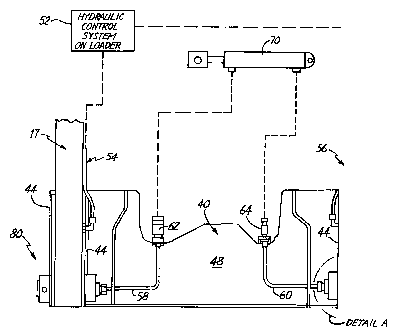
Refer now to Figure 3A which illustrates a
rear view of attachment adapter plate 40 connected to
boom arms 17 by load bearing pivot assemblie, 30. The
load bearing pivot assemblies 80 receive hydraulic fluid
from the hydraulic control system 52 on the loader 10 by
way of hydraulic lines 54 and 56. The hydrauli c control
system 52 on the loader 10 is only shown schematically
and is well known in the art. Hydraulic fluid received
from the hydraulic control system 52 passes through the
hydraulic lines 54 and 56 into the load bearing pivot
assemblies 80 and exit through hydraulic lines 58 and
60.
The hydraulic lines 54 and 56 are preferably
at least partially contained within the boom arms 17.
This protects the hydraulic lines 54 and 56 from damage
due to the abusive environment. Similarly, hydraulic
lines 58 and 60 are preferably, at least partially
contained within the adapter plate 40. Protection for
the hydraulic lines 54, 56, 58 and 60 may be provided
by, for example, indents or recesses in the boom arms 17
and the attachment adapter plate 40. Those skilled in
the art will recognize other suitable means to protect
CA 02298040 2000-02-02
-10-
the hydraulic lines within the boom arms 17 and the
adapter plate 40.
A pair of quick couplers 62 and 64 are
preferably connected to the ends of hydraulic lines 58
and 60, respectively. The quick couplers 62 and 64 are,
in turn, connected to a hydraulic actuator 70, which is
shown as a double-acting cylinder for illustrative
purposes only. The hydraulic actuator 70 generally
represents any hydraulic actuator such as a hydraulic
cylinder or a hydraulic motor utilized on the
attachment.
With this arrangement, hydraulic fluid
delivered from the hydraulic control system 52 on the
loader 10 passes through hydraulic lines 54 and 56
preferably contained at least partially within the boom
arms 17. The pressurized hydraulic fluid contained in
the hydraulic lines 54 and 56 then passes through the
load bearing pivot assemblies 80 and exits through
hydraulic lines 58 nd 60. Hydraulic lines 58 and 60 are
connected to a hydraulic actuator 70 by suitable
connectors and lines such as quick couplers 62 and 64.
Accordingly, the hydraulic control system 52 on the
loader 10 controls the function of the hydraulic
actuator 70 on the attachment (not shown) by way of the
hydraulic lines 54, 56 through load bearing pivot
assemblies 80 and through hydraulic lines 58 and 60.
Refer now to Figure 3B which illustrates a
movable block assembly 66 for connecting pressure lines
58 and 60 to the hydraulic actuator 70 (not shown) . The
remaining portions of the loader 10 and attachment not
illustrated in Figure 3B are the same as those discussed
previously. The movable block assembly 66 is connected
to the adapter plate 40, and preferably the back plate
48, using rod 67 and brackets 68. Rod 67 may be welded
CA 02298040 2000-02-02
-11-
to the back plate 48 by brackets 68. The movable block
assembly 66, in turn, includes a hole 69 to receive the
rod 67. With this arrangement, the movable block 66 is
able to slide along the rod 67 and rotate about the axis
of the rod 67. Those skilled in the art will recognize
that there are many suitable ways to connect the movable
block 66 to the adapter plate 40 such that the block 66
is capable of relative movement. Preferably, the block
66 is capable of both lateral and rotational movement
with respect to the adapter plate 40.
With reference to Figure 3C, movable block
assembly 66 includes a quick coupler 72 in fluid
communication with the hydraulic line 60. In a similar
manner, another quick coupler (not shown) is connected
to movable block assembly 66 and is in fluid
communication with hydraulic line 58. The quick
couplers, including quick coupler 72, and the other
quick coupler (not visible) are adapted to be received
by mating couplers on the attachment.
With this arrangement, the movable block 66
may be positioned relative to the attachment by moving
the attachment adapter plate 40 with the hydraulic
cylinders 22 and 32. Together with a remote lock
mechanism for connecting the adapter plate 40 to the
attachment as described previously, an operator may
remain in cab 16 and maneuver the loader 10 to connect
the adapter plate 40 and the hydraulic couplers on the
movable block 66 to the attachment. In this manner, the
operator may easily establish both hydraulic and
physical connections between the loader 10 and the
attachment without exiting the cab 16.
Refer now to Figure 4 which illustrates a
partially cross-sectioned detailed view of the load
bearing pivot assembly 80 of the present invention. The
CA 02298040 2000-02-02
-12-
pivot assembly 80 includes a pin 82 rigidly secured to
brackets 44 of the adapter plate 40. Surrounding pin 82
is annular bushing 84 which is pressed into a bore in
boom arm 17, and which has wipers 86 and seals 88
adjacent the ends of the bore. The pin 82 freely
rotates within the bushing 84.
Although the pivot assembly 80 illustrated in
Figure 4 illustrates the pin 82 rigidly connected to the
adapter plate 40 and the bushing 84 rigidly connected to
the boom arm 17, it is contemplated that the arrangement
may be reversed. In other words, the pin 82 may be
connected to the boom arm 17 and the bushing 84 may be
connected to the attachment adapter plate 40. In this
embodiment, the boom arm 17 may include two extension
brackets (not shown) to connect to either side of the
pin 82. Additionally, the attachment plate 40 may
include a bearing housing (not shown) to contain the
bushing 84. Those skilled in the art will recognize
that many pivotal assemblies and arrangements are
possible without departing from the spirit of the
invention.
Pin 82 includes a longitudinal bore 92, one or
more lateral bores 94 and an annular recess 96, which
aligns with cross bores 98 in the bushing 84. In this
manner, a fluid path is defined through the center of
pin 82 to the cross bores 98. The annular bushing 84
includes holes 98 which are disposed adjacent the
annular recess 96 in the pin 82. An inlet or entrance
port 104 for hydraulic fluid opens to a cross bore 102
which intersects a bore in the boom arm 17. The bore
100 is in fluid communication with the cross bores 98 in
the bushing 84. An annular recess 99 is formed
surrounding the bores 98, either in bushing 84 or in the
bore in boom arm 17 holding the bushing. 0-rings 90
CA 02298040 2000-02-02
-13
seal the recess 99. With this arrangement, fluid inlet
or entrance port 104 is in communication with an exit
port 106 of pin 82 by way of cross bore 102, bore 100,
annular recess 99, bores 98, annular recess 96, bores
94, and longitudinal bore 92. Since a fluid-tight seal
is provided between the pin 82 and the bushing 84, and
between bushing 84 and its bore in boom arm 17 (with
seals 90) a fluid-tight path is established between the
entrance port 104 and the exit port 106.
The entrance port 104 may be coupled to the
hydraulic lines 56 or 54 depending on which side the
pivot assembly 80 is located. Similarly, the exit port
106 may be connected to the hydraulic lines 58 or 60
depending on which side the pivot assembly 80 is
located. In essence, the load bearing pivot assembly 80
provides a pivotable connection between the boom arm 17
and the adapter plate 40 in addition to a fluid path
therethrough. This construction eliminates hydraulic
fluid lines at the pivot points which would otherwise be
susceptible to failure due to repeated flexure and/or
due to exposure to an abusive environment.
As fluid flows from the entrance port 104 to
the exit port 106 of the pivot assembly 80, the
hydraulic fluid flows along the bearing surfaces of the
bushing 84 and the pin 82. Because most hydraulic
fluids have an inherent lubricant property, the flow of
hydraulic fluid through the pivot assembly 80
automatically lubricates the bearing surfaces of the
bushing 84 and pin 82. Pivot assembly 80 also includes
a removable plug 108 that plugs bore 100 at its outer
end. It can be used for draining hydraulic fluid from
the pivot assembly 80.
The load bearing pivot assembly may also be
utilized at pivot point 20 between the boom arm 17 and
CA 02298040 2000-02-02
-14-
the main frame 12. Hydraulic lines passing from the
main frame 12 to the boom arm 17 could be routed through
the load bearing pivot assembly 80 located at pivot
point 20 and thereby eliminate the need for hydraulic
lines at pivot point 20 which would otherwise be
susceptible to failure due to repeated flexure and
exposure to the abusive environment.
Although the present invention has been
described with reference to preferred embodiments, those
skilled in the art will recognize that changes may be
made in form and detail without departing from the
spirit and scope of the invention, as described in the
appended claims.