Note: Descriptions are shown in the official language in which they were submitted.
"CONCRETE SUPPLY ARM WITH ARTICULATED SECTIONS"
n ,r ,gin o., na ee no on
f~IhAA'' ~oow .~n,a nno0
~ ~ o o n ao A n a a a n a ,i
n n ~ n ~, a s o n w a eee eae
n ~, n o n a a a a a a
n , 00 oe w w w m
The present invention relates to concrete supply arms ~x~aCx
~ax~i~ctaxxa~c mounted on vehicle-transported concrete pumps xx
~ for moving said arm sections a ong vertical planes
having several sections and articu atmg ~omts etween say section .
vertically movin
Various types of multiple-se- coon / concrete supply arms are
already well known, said arms being of the kind in which the relative
alon vertical lanes
movement of the sections is performe , ~n correspondence of the
articulating joints, by means of kinematic mechanisms with articulated
rods connected to the sections and double-acting hydraulic cylinders
controlling them.
These constructions, however, have the drawback that the
angular velocities at which the arm sections are moved are not
constant (the angles of relative movement of the sections are not
proportional to the stroke of the cylinder) and the significant limitation
that, even when using complicated kinematic mechanisms, the angle
of maximum relative rotation of the sections is generally not greater
than 2$0°
It can be easily understood how important it is to avoid the
abovementioned drawback and limitation of the known constructions,
in order to achieve greater operational efficiency and safety and have
a greater degree of manoeuvrability and versatility during use of the
concrete supply arms, in particular along the sections and at the
articulating joints closest to the delivery end of the arms themselves.
From UK-A-2132676 is fiuthermore known an apparatus for horizontally casting
concrete, which
comprises several arm sections and articulation joints between them, wherein
the relative movement
of the sections is performed by means of actuator mechanisms consisting of a
worm gear actuated
by a hydraulic motor.
In this apparatus the actuator mechanisms must only provide said movement -
which occurs along
an horizontal plane - without supporting the weight of the single arm
sections.
Surprisingly, it has been now found that the actuator mechanisms, of the kind
of the ones used on
the apparatus of UK-A-2132676, may be applied with success in a concrete
supply arm, the arm
sections of which are foreseen for reciprocal movements along vertical planes
( so that the weight of
the single arm sections is at least in part supported by said actuator
mechanisms).
More in details the present application is thus relative to a concrete supply
arm - to be mounted on
vehicle-transported concrete pumps - having several sections and
for moving said arm sections alo vertical planes,
articulating joints between said sections, character~zad in that the
relative movement of the sections is performed, in correspondence of
at least some of the articulating joints of the arm, by means of
actuator mechanisms consisting of a worm gear actuated by a
ca o229ssos Zooo-oi-ZS ~MENpED S;~ii:;T
1
1 '.
, .1 ~ ~ , 19 ~~ AA nU
n., , , rn 1 ~ a ~ ~ n n "
., o , ., r~. ' , n ~ ~ ~ n n
~ . n o ~ , , n , s ~~~ ~ vee non
t , , n , ~ n ~ ~ ~ n
o ~~ on o~ s~ W W w
hydraulic motor.
Preferably said actuators also comprise a locking brake.
Conveniently in the arm according to the invention the relative
movement of the sections is performed by means of actua:or
mechanisms consisting of a worm gear actuated by a hydraulic moor
only at the articulating joints close to the delivery end o. the arm.
With arms constructed in this manner, the angular velocity at
which the relative movement of the sections takes place may be kept
constant, without difficulty, over the entire amplitude of the relative
angular displacements and the latter may also be much greater than
280°, with obvious advantages for the operators and improvement in
the quality of the work.
The invention is now described in greater detail 4vith reference
to the accompanying drawings which relate to some preferred
multi ~le.-section vertically moving concrete sub
1 S em6~ments or t a arm' according to t~ mvennon, as defined above
and in which:
Fig. 1 is a schematic view of the 2rticulation betLVeen two end
multiple section vertically moving
sections o'r a/concrete supply arm according to the pr for art;
Figs. 2 and 3 are two schematic views - a side view and a plan
verticall moving
view - of an articulating joint between two sections o concrete
supply arm equipped, according to a first embodiment of the
invention, with an internal actuator;
Figs. 4 and 5 are two similar schematic views of a different
embodiment o. the solution according to Figs. 2 and 3;
Figs. 6 and 7 are two similar schematic vie~~rs of a further
embodiment o. the solution according to Figs. 2 and 3;
Figs. 8 and 9 are two schematic views - a side view and a plan
vertically movins~
view - of an articulating joint between two sections of a/concrete
supply arm equipped, according to another embodiment of the
invention, with an external actuator; and
Fig. 10 shows in detail a sectional view of a possible
2
CA 02298508 2000-O1-28
AMENDED SI;wT
WO 99/06650 PCT/EP98/04588
construction of one of the actuators applied to the embodiments of
Figs. 2 to 9, of the invention.
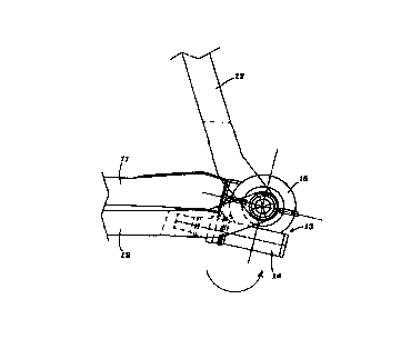
With reference to the drawings, Fig. 1 shows a schematic view
of the construction of an articulation or articulating joint between two
end sections of a concrete supply arm according to the prior art: the
two sections 1 and 2 are connected by a kinematic mechanism
comprising two connecting rods 3 and 4 which are pivotably hinged
at 5, 6 and 7 to the two sections 1 and 2 and to one another and a
double-acting hydraulic cylinder-piston unit 8, the cylinder of which is
pivotably hinged at the closed end at 9 to a lug 1 A of the section 1
and the piston of which is pivotably hinged at 10 with its outer end to
the connecting rod 3, so as to control the movement of the section 2
with respect to the section 1. It is obvious from this figure that the
maximum angle by which the section 2 is able to be rotated with
respect to the section 1 does not exceed 280° tit is equivalent to
about 270°), while the angular velocities at which the sections of the
arm may be moved are not constant, but continuously variable, since
the angles of relative movement of the sections are not proportional
to the stroke of the cylinder.
According to the invention, these drawbacks - which result, as
already mentioned, in the poor operational efficiency and safety and in
particular in a degree of manoeuvrability and versatility far inferior to
that which is desirable in the use of the concrete supply arms - are
eliminated by performing the relative movement of the sections, in
correspondence of at least some of the articulating joints of the arm,
by means of actuator mechanisms consisting of a worm gear actuated
by a hydraulic motor and applied in various ways, as illustrated in
Figs. 2 to 10.
In the embodiment according to Figs. 2 and 3 of the invention,
an internal actuator 13, in line with both the sections 11 and 12 of
the arm, is used. The actuator comprises a worm gear consisting of a
3
CA 02298508 2000-O1-28
WO 99/06650 PCT/EP98/04588
worm screw housed in a casing 14 and of a wheel in engagement
with said screw, housed inside a casing 15, the latter being located in
a special seat 16 formed at the end of the section 11 of the arm. The
casing 14 also houses a hydraulic motor which - suitably energised -
causes rotation of the the worm screw of the actuator and produces
the rotations, in either direction, of the associated wheel, moving the
section 12 with respect to the section 11. The actuator also
comprises preferably parking brake means so as to lock as securely as
possible the two sections 11 and 12 in the desired position. It can be
clearly seen that it is possible to exceed without difficulty, using this
solution, an angle of movement of the section 12 with respect to the
section 11 which is far greater than 280° and it is obvious that, by
using the actuator 13, it is possible to achieve a constant angular
velocity during the movement.
In the embodiment according to Figs. 4 and 5, the actuator 13
is again internal and in line with both the sections, but the rest
position of the latter, which in the preceding case consisted in the
elements resting on top of each other (section 12 folded underneath
the section 11 ), in this case consists in the elements being aligned
with each other, with the section 12 which is at rest being arranged
aligned as a continuation of the section 11.
In the embodiment according to Figs. 6 and 7, on the other
hand, the actuator 13 is again internal, but is in line with only one of
the sections of the arm to be moved relative to one another, for
example with the section 11. With this construction it is possible to
obtain a continuous rotary movement of the section 12 with respect
to the section 11 and the locking of the former with respect to the
latter in any position over the entire angle of 360°.
In the embodiment according to Figs. 8 and 9 of the invention,
an actuator 23 which is located outside both the sections 21 and 22
of the arm is used. The actuator comprises a worm screw housed in
4
CA 02298508 2000-O1-28
WO 99/06650 PC1'/EP98/04588
a casing 24 and a wheel in engagement with said screw, housed in a
casing 25. The casing 24 also houses a hydraulic motor which -
suitably energised - causes rotation of the worm screw of the
actuator and produces rotations, in either direction, of the associated
wheel, moving the section 22 with respect to the section 21. The
actuator is arranged alongside the ends of the sections 21 and 22
which are articulated with one another and is connected to the
section 21 by an anti-torsional bar 21 A and to the section 22 by the
output shaft moved by the wheel housed inside the casing 25. In this
case, also, the actuator preferably comprises locking brake means, so
as to lock as securely as possible the two sections 21 and 22 in the
desired position. 1n this case also it is possible to exceed, without
difficulty, an angle of movement of the section 22 with respect to the
section 21 which is tar greater than 280° with a constant angular-
velocity movement.
Fig. 10 illustrates a possible construction of an actuator 30 to
be applied to any one of the embodiments according to Figs. 2 and 9
of the concrete supply arm according to the invention. The actuator
illustrated comprises, inside a casing 31 to be associated with the arm
by means of the lug 31 A, a transmission consisting of a worm screw
32 and of a wheel 33 housed respectively in the parts 34 and 35 of
the casing 31, with which there are also associated an orbital
hydraulic motor 36, which causes rotation, whenever suitably
energised, of the worm screw 32 and a lamellar brake 37 intended to
lock in the desired position the shaft of the screw 32 and hence the
two sections of the arm on the articulating joint of which the actuator
is mounted.
It is understood that the construction of the concrete supply
arm according to the invention may differ from those described and
30 illustrated. In particular different actuators may be used, being
differently driven or differently arranged with respect to that
5
CA 02298508 2000-O1-28
;~~v '
o ,» >0 00 oe eo 0o
n~ i.i n n .~ ~~ n o n a a o o a -
~, , , o n nn a n o v a o 0 0
1 0 ~ n o 0 0 o a a eee o eeo 000
, o n o a a o a o 0
shOWfl ~ n o.~ o0 on ee W ev
~, without thereby departing from the protective scope of the
invention, as described by the appended claims.
6
ca o229ssos Zooo-oi-ZS ANjENDEF~ Si~~=~T