Language selection

Search

Patent 2298672 Summary

Third-party information liability

Some of the information on this Web page has been provided by external sources. The Government of Canada is not responsible for the accuracy, reliability or currency of the information supplied by external sources. Users wishing to rely upon this information should consult directly with the source of the information. Content provided by external sources is not subject to official languages, privacy and accessibility requirements.

Claims and Abstract availability

Any discrepancies in the text and image of the Claims and Abstract are due to differing posting times. Text of the Claims and Abstract are posted:

  • At the time the application is open to public inspection;
  • At the time of issue of the patent (grant).
(12) Patent: (11) CA 2298672
(54) English Title: SYSTEM FOR FIXING ROTARY CUTTING DIES IN MACHINES FOR DIE CUTTING LAMINAR MATERIAL
(54) French Title: SYSTEME DE FIXATION DE MATRICES ROTATIVES DANS DES DECOUPEUSES DE MATERIAU STRATIFIE
Status: Expired and beyond the Period of Reversal
Bibliographic Data
(51) International Patent Classification (IPC):
  • B26D 7/26 (2006.01)
  • B26F 1/44 (2006.01)
(72) Inventors :
  • SERRA OBIOL, RAMON (Spain)
(73) Owners :
  • COMERCIAL INDUSTRIAL MAQUINARIA CARTON ONDULADO, S.L.
(71) Applicants :
  • COMERCIAL INDUSTRIAL MAQUINARIA CARTON ONDULADO, S.L. (Spain)
(74) Agent: ROBIC AGENCE PI S.E.C./ROBIC IP AGENCY LP
(74) Associate agent:
(45) Issued: 2007-04-24
(86) PCT Filing Date: 1999-05-28
(87) Open to Public Inspection: 1999-12-09
Examination requested: 2004-01-20
Availability of licence: N/A
Dedicated to the Public: N/A
(25) Language of filing: English

Patent Cooperation Treaty (PCT): Yes
(86) PCT Filing Number: PCT/ES1999/000157
(87) International Publication Number: WO 1999062778
(85) National Entry: 2000-01-31

(30) Application Priority Data:
Application No. Country/Territory Date
P 9801136 (Spain) 1998-06-01

Abstracts

English Abstract


System for fixing rotary die cutters in die cutting
machines for cutting laminar material, said system
comprising fixing means between the die (1) and a
die-holder surface or cylinder (2) around which the
die (1) is arranged, wherein the fixing means include a
plurality of bolts (3) actuated by an actuator (5) housed
inside a hollow body (8) fixed to the die-holder cylinder
(2) in order to provide for a rapid fixing of the rotary
die to the die-holder cylinder.


French Abstract

L'invention concerne un système de fixation de matrices rotatives dans des découpeuses de matériau stratifié qui est équipé de moyens de fixation placés entre la matrice (1) et un cylindre ou surface porte-matrice (2), autour duquel est disposée la matrice (1). Les moyens de fixation comprennent une pluralité de goujons (3) actionnés par un dispositif de commande (5) logé à l'intérieur d'un corps creux (8) fixé au cylindre porte-matrice (2), ce qui permet de fixer rapidement la matrice rotative au cylindre porte-matrice.

Claims

Note: Claims are shown in the official language in which they were submitted.

8
WHAT IS CLAIMED IS:
1. A system for fixing rotary dies on die cutting machines of laminar
material,
comprising fixing means of the die (1) and a die holder cylinder or surface
(2),
around which the die (1) is arranged, the fixing means having a plurality of
bolts
(3) actuated by an actuating device housed inside a hollow body (8) fixed to
the
die holder cylinder or surface (2), characterized in that the bolts (3)
comprise an
area of larger diameter (7) on their head fixing the die (1) to the die holder
cylinder or surface (2), incorporating actuating devices configured as fluid
dynamic cylinders (5) in the case of a die holding cylinder (2), the fluid
dynamic
cylinders (5) acting independently in the two 180° halves of the die
holder
cylinder (2), the cylinders being fluid dynamic (5), pneumatic or hydraulic
cylinders in the case of die (1) being rotating.
2. A system for fixing rotary dies on die cutting machines of laminar
material,
according to claim 1, characterized in that the bolts (3) are quincuncially
placed
on the rotating cylinder or on a flat surface.
3. A system for fixing rotary dies on die cutting machines of laminar
material,
according to claim 1, characterized in that it is provided with treaded drills
(22) to
fix the rotating die (1) to the die cylinder (2).
4. A system for fixing rotating dies on die cutting machines of laminar
material, according to any one of claims 1 to 3, characterized in that the
drills
(22) are also quincuncially placed on the rotating die (1), occupying the
locations
not occupied by the bolts (3).
5. A system for fixing rotating dies on die cutting machines of laminar
material, according to any one of claims 1 to 4, characterized in that it has
springs (13) and (14) acting on the bolt (3), the latter being located inside
the
hollow piston (6) when the outlet of the bolt (3) is obstructed by the die
(1).

9
6. A system for fixing rotating dies on die cutting machines of laminar
material, according to any one of claims 1 to 5, characterized in that the die
(1)
is centered on the die holder cylinder (2).
7. A system for fixing rotating dies on die cutting machines of laminar
material, according to any one of claims 1 to 6, characterized in that it has
a
circumferential butt (19) and an axial butt (20) on the die holder cylinder,
and a
reglet (21) on the die (1) for centering it.
8. A system for fixing rotating dies on die cutting machines of laminar
material, according to any one of claims 1 to 7, characterized in that it has
a hole
(15) with a swivel (16) and a recess (17) carried out on the wood of the die
so
that, after shifting the wood and removing the air from the corresponding
fluid
dynamic cylinder (5), the bolt's (3) head (7) fixes the die (1) against the
die
holder cylinder (2).

Description

Note: Descriptions are shown in the official language in which they were submitted.


CA 02298672 2000-O1-31
1
SYSTEM FOR FIXING ROTARY CUTTING DIES IN
MACHINES FOR DIE CUTTING LAMINAR MATERIAL
DESCRIPTION
PURPOSE
10 This descriptive report refers to a system for
fixing rotary cutting dies in machines for die cutting
laminar material, the purpose of which lies in its
configuration as a system that permits fixing rotary
cutting dies on the cylinders or cutting die supports
15 in machines for die cutting laminar material.
SCOPE
This invention is applied within the industry
20 dedicated to the manufacture of die cutting machines,
especially machines for die cutting laminar material.
HISTORY
25 In rotary cutting die machines, the material to
be cut, for example cardboard for making boxes, is
moved between a cutting die support cylinder and a
counter-cutting die cylinder or anvil, also rotary, so
that at each turn of the cylinders the cutting die
30 falls on the counter-cutting die and makes a cut or
warping on the cardboard.
To avoid that the cutting die becomes damaged by
the blow, the surface of the counter-cutting die is
35 provided with a polyurethane coating.

CA 02298672 2006-06-07
2
At present, the rotary cutting dies are fixed on
the cutting die support by means of screws that are
coupled to the corresponding screw holes made on the
surface of the cutting die support cylinder.
This fixing system has the main inconvenience
that it is excessively slow, as a considerable number
of screws has to be placed.
The statement made in the above paragraph
confirms that the stopping time of the machine when a
new cutting die has to be mounted is excessive and
this affects the productivity of the rotary cutting
die machine.
DESCRIPTION OF THE INVENTION
The system for fixing rotary cutting dies in
machines for die cutting laminar material proposed by
the invention is formed in itself as a novelty that manages to resolve the
above
mentioned inconvenience and, furthermore, presents other advantages to be
described later on.
According to the present invention, there is provided a system for fixing
rotary dies on die cutting machines of laminar material, comprising fixing
means
of the die and a die holder cylinder or surface, around which the die is
arranged,
the fixing means having a plurality of bolts actuated by an actuating device
housed inside a hollow body fixed to the die holder cylinder or surface,
characterized in that the bolts comprise an area of larger diameter on their
head
fixing the die to the die holder cylinder or surface, incorporating actuating
devices configured as fluid dynamic cylinders in the case of a die holding
cylinder, the fluid dynamic cylinders acting independently in the two
180° halves
of the die holder cylinder, the cylinders being fluid dynamic, pneumatic or
hydraulic cylinders in the case of die being rotating.

CA 02298672 2006-06-07
3
This characteristic permits rapid fixing of the rotary cutting die to the
cutting die support cylinder, with the result that the shutdown time of the
machine to change the cutting die is less than at present, improving the
productivity of the cutting die machine.
Preferably, the system of the invention also has the peculiarity that each
of the working devices is housed inside a hollow body fixed to the cutting die
support cylinder.
Thanks to this characteristic the manufacturing costs of the cutting die
machine are not overexpensive, in turn permitting that maintenance and
mechanization of the machine are quick and easy.
Preferably, the working devices are also dynamic fluid cylinders that
operate independently in the two halves of the cutting die support cylinder.
Preferably, according to their performance, the dynamic fluid cylinders
are pneumatic or hydraulic cylinders and also preferred the working devices
are
dynamic fluid cylinders that operate independent of the two halves of the
cutting
die support cylinder.
Preferably, likewise, according to their performance, the dynamic fluid
cylinders are pneumatic or hydraulic cylinders and it should be indicated that
it is
also preferred that the bolts are placed on the rotary cutting die in
quincunxes
with the result that the bolts occupy the whole surface of the cutting die in
a
uniform way.
Preferably, according to a performance, the system of the invention also
includes screwed drill holes to fix the rotary cutting die to the cutting die
support
cylinder, placing these screwed drill holes to ensure fixing of the rotary
cutting
die to the cutting die

,, CA 02298672 2000-O1-31
4
support cylinder in the event the system purpose of
this invention is not used.
Preferably, the drill holes are also placed on
the cutting die support cylinder in quincunxes,
occupying the places that have not been used by the
bolts.
DESCRIPTION OF THE DRAWINGS
To complement the description which follows and
in order to help with a better understanding of the
characteristics of the invention, this descriptive
report includes a set of drawings in which the
following is represented in an illustrative but not
limiting way:
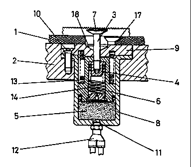
Figure 1 shows an elevated section view of a
working device.
Figure 2 shows a view in perspective of a cutting
die placed on a cutting die support cylinder.
Figure 3 shows a detail of the centering system
of the cutting die on the cutting die support
cylinder.
Figure 4 shows a fixing hole of the cutting die.
Figures 5, 6, 7 and 8 correspond to elevated
section views of the four working positions of the
working device relating to the system for fixing
rotary cutting dies in machined for die cutting
laminar material, the purpose of this invention.

CA 02298672 2000-O1-31
5
PREFERRED PERFORMANCE OF THE INVENTION
5 In view of these figures, it can be seen how the
system for fixing rotary cutting dies in machines for
die cutting laminar material is made up of rotary
cutting dies (1) which are fixed to cutting die
support cylinders (2) by means of a number of bolts
10 (3) worked by a pneumatic cylinder (5).
The bolts (3) are ffixed to the piston (6) of the
pneumatic cylinder ( 5 ) by a screw nut ( 4 ) the head ( 7 )
of which has a larger diameter that fixes the cutting
15 die (1) to the cutting die support cylinder (2).
The pneumatic cylinders (5) are housed inside two
hollow bodies (8) and each of these hollow bodies (8)
is fixed to the cutting die support cylinder (2) by
20 means of four fixing screws (10).
As can be seen in figure 2, the bolts (3) are
placed on cutting die support cylinders (2) and on the
rotary cutting die (1) in quincunxes, so that they
25 occupy the whole surface of the cutting die (1) in a
uniform way.
In figure 3 it can be seen that, in order to
center the cutting die (1) on the cutting die support
30 cylinder (3), this has a circumferential butt (19) and
an axial butt (20) for centering the cutting die (1),
whilst the cutting die (1) has a centering guide (21).
The fixing system can also include screwed drill
35 holes (22) to fix the rotary cutting die (1) to the
cutting die support cylinder (2) and, in this case,

CA 02298672 2006-06-07
6
the screwed drill holes (22) are also placed on the
cutting die support cylinder (2) and on the rotary
cutting die (1) in quincunxes, occupying the places
that have not been previously occupied by the bolts
(3) .
At the bottom of each pneumatic cylinder (5)
there is an orifice (11) connected to a duct (12) for
injecting pressurized air. In the event that the bolt
(3) does not find any hole (15) in the cutting die (1)
through which it can exit, the system of the invention
has a hollow piston ( 6 ) that has a spring ( 14 ) inside
which gives way and permits the bolt (3) to remain
hidden inside the piston (6) and in a hollow (18) in
the lid (9) of the pneumatic cylinder. This lid (9) is
fixed to the cutting die (1) with the same screws (10)
as the hollow body (8).
The holes (15) of the cutting die (1 ) are provided with a swivel (16)
provided with recess (17) with the shape of the head (7) of the bolt (3).
The different work stages of the working devices
can be seen in figure 5.
The above mentioned stages of the working devices
are as follows:
First stage - Whilst the pneumatic cylinder
(figure 5) has no pressurized air, the spring (13)
pushes the bolt (3) towards the inside of the hollow
body (8). The cutting die (1)is placed on the cutting
die support cylinder (2), butting against the
circumferential butt (19) and the centering axial butt
(20) of the cutting die support cylinder (2).

CA 02298672 2006-06-07
7
Second stage - The pneumatic cylinder, as shown
in figures 6 and 7, receives the pressurized air
through an orifice (11) made at the bottom of the
pneumatic cylinder (5), connected to a duct (12),
driving this pressurized air upwards to the piston (6)
and, at the same, the bolt (3), thus overcoming the
stress of the spring (13), as shown in figure 7.
In the hypothetical case that the outlet of the
bolt (3) was obstructed, the pressurized air would
continue to overcome the stress of the spring (13),
thus maintaining the piston up, but the bolt (3) would
remain hidden inside the piston (6), thus placing
small pressure produced by the spring (19) on the
cutting die (1), as shown in figure 6.
Third stage - In this stage the cutting die ( 1 )
must be moved axially towards the position of the
swivel (16) and then eliminate the pressurized air
from inside the pneumatic cylinder, thus obtaining
that the spring (13) works and in this way moves the
piston ( 6 ) and the bolt ( 3 ) towards the inside of the
cutting die support cylinder (2), thus fixing the head
(7) of the bolt (3) and the cutting die (1) to the
cutting die support cylinder (2), as shown in figure
8.

Representative Drawing
A single figure which represents the drawing illustrating the invention.
Administrative Status

2024-08-01:As part of the Next Generation Patents (NGP) transition, the Canadian Patents Database (CPD) now contains a more detailed Event History, which replicates the Event Log of our new back-office solution.

Please note that "Inactive:" events refers to events no longer in use in our new back-office solution.

For a clearer understanding of the status of the application/patent presented on this page, the site Disclaimer , as well as the definitions for Patent , Event History , Maintenance Fee  and Payment History  should be consulted.

Event History

Description Date
Time Limit for Reversal Expired 2016-05-30
Letter Sent 2015-05-28
Maintenance Request Received 2014-04-16
Reinstatement Request Received 2012-12-28
Inactive: Late MF processed 2012-12-28
Maintenance Request Received 2012-12-28
Letter Sent 2012-05-28
Inactive: Correspondence - MF 2010-08-10
Inactive: Office letter 2008-08-22
Inactive: Correspondence - Transfer 2008-04-15
Letter Sent 2007-11-26
Inactive: Single transfer 2007-10-10
Grant by Issuance 2007-04-24
Inactive: Cover page published 2007-04-23
Inactive: Final fee received 2007-02-08
Pre-grant 2007-02-08
Letter Sent 2006-08-09
Notice of Allowance is Issued 2006-08-09
Inactive: Approved for allowance (AFA) 2006-07-24
Amendment Received - Voluntary Amendment 2006-06-07
Inactive: S.30(2) Rules - Examiner requisition 2006-02-03
Small Entity Declaration Determined Compliant 2005-07-02
Letter Sent 2004-02-02
Request for Examination Requirements Determined Compliant 2004-01-20
All Requirements for Examination Determined Compliant 2004-01-20
Request for Examination Received 2004-01-20
Inactive: Cover page published 2000-03-30
Inactive: IPC assigned 2000-03-29
Inactive: First IPC assigned 2000-03-29
Letter Sent 2000-03-14
Inactive: Notice - National entry - No RFE 2000-03-14
Application Received - PCT 2000-03-13
Application Published (Open to Public Inspection) 1999-12-09

Abandonment History

Abandonment Date Reason Reinstatement Date
2012-12-28

Maintenance Fee

The last payment was received on 2006-05-19

Note : If the full payment has not been received on or before the date indicated, a further fee may be required which may be one of the following

  • the reinstatement fee;
  • the late payment fee; or
  • additional fee to reverse deemed expiry.

Please refer to the CIPO Patent Fees web page to see all current fee amounts.

Fee History

Fee Type Anniversary Year Due Date Paid Date
Registration of a document 2000-01-31
Basic national fee - small 2000-01-31
MF (application, 2nd anniv.) - small 02 2001-05-28 2001-04-12
MF (application, 3rd anniv.) - small 03 2002-05-28 2002-05-14
MF (application, 4th anniv.) - small 04 2003-05-28 2003-05-21
Request for examination - small 2004-01-20
MF (application, 5th anniv.) - small 05 2004-05-28 2004-05-25
MF (application, 6th anniv.) - small 06 2005-05-30 2005-05-17
MF (application, 7th anniv.) - small 07 2006-05-29 2006-05-19
Final fee - small 2007-02-08
MF (patent, 8th anniv.) - small 2007-05-28 2007-04-19
Registration of a document 2007-10-10
MF (patent, 9th anniv.) - small 2008-05-28 2008-05-20
MF (patent, 10th anniv.) - small 2009-05-28 2009-04-24
MF (patent, 11th anniv.) - small 2010-05-28 2010-04-27
MF (patent, 12th anniv.) - small 2011-05-30 2011-04-26
MF (patent, 13th anniv.) - small 2012-05-28 2012-12-28
Reversal of deemed expiry 2012-05-28 2012-12-28
MF (patent, 14th anniv.) - small 2013-05-28 2012-12-28
MF (patent, 15th anniv.) - small 2014-05-28 2014-04-16
Owners on Record

Note: Records showing the ownership history in alphabetical order.

Current Owners on Record
COMERCIAL INDUSTRIAL MAQUINARIA CARTON ONDULADO, S.L.
Past Owners on Record
RAMON SERRA OBIOL
Past Owners that do not appear in the "Owners on Record" listing will appear in other documentation within the application.
Documents

To view selected files, please enter reCAPTCHA code :


To view images, click a link in the Document Description column. To download the documents, select one or more checkboxes in the first column and then click the "Download Selected in PDF format (Zip Archive)" or the "Download Selected as Single PDF" button.

List of published and non-published patent-specific documents on the CPD .

If you have any difficulty accessing content, you can call the Client Service Centre at 1-866-997-1936 or send them an e-mail at CIPO Client Service Centre.


Document
Description 
Date
(yyyy-mm-dd) 
Number of pages   Size of Image (KB) 
Representative drawing 2000-03-30 1 10
Description 2000-01-31 7 226
Drawings 2000-01-31 4 98
Claims 2000-01-31 3 86
Abstract 2000-01-31 1 75
Cover Page 2000-03-30 1 45
Description 2006-06-07 7 227
Claims 2006-06-07 2 66
Representative drawing 2007-04-04 1 16
Cover Page 2007-04-04 1 46
Notice of National Entry 2000-03-14 1 193
Courtesy - Certificate of registration (related document(s)) 2000-03-14 1 113
Reminder of maintenance fee due 2001-01-30 1 112
Reminder - Request for Examination 2004-01-29 1 113
Acknowledgement of Request for Examination 2004-02-02 1 174
Commissioner's Notice - Application Found Allowable 2006-08-09 1 162
Courtesy - Certificate of registration (related document(s)) 2007-11-26 1 104
Courtesy - Certificate of registration (related document(s)) 2007-11-26 1 103
Maintenance Fee Notice 2012-07-09 1 171
Late Payment Acknowledgement 2013-01-09 1 163
Maintenance Fee Notice 2015-07-09 1 170
PCT 2000-01-31 3 122
Correspondence 2000-04-07 2 64
Fees 2003-05-21 1 27
Fees 2001-04-12 1 32
Fees 2002-05-14 1 30
Fees 2004-05-25 1 31
Fees 2005-05-17 1 32
Fees 2006-05-19 1 31
Correspondence 2007-01-02 3 83
Correspondence 2007-02-08 1 41
Fees 2007-04-19 1 45
Correspondence 2008-08-22 2 11
Fees 2008-05-20 1 47
Correspondence 2010-08-10 1 45
Correspondence 2012-07-09 1 82
Fees 2012-12-28 1 44
Fees 2012-12-28 1 41
Fees 2014-04-16 1 33