Language selection

Search

Patent 2299088 Summary

Third-party information liability

Some of the information on this Web page has been provided by external sources. The Government of Canada is not responsible for the accuracy, reliability or currency of the information supplied by external sources. Users wishing to rely upon this information should consult directly with the source of the information. Content provided by external sources is not subject to official languages, privacy and accessibility requirements.

Claims and Abstract availability

Any discrepancies in the text and image of the Claims and Abstract are due to differing posting times. Text of the Claims and Abstract are posted:

  • At the time the application is open to public inspection;
  • At the time of issue of the patent (grant).
(12) Patent: (11) CA 2299088
(54) English Title: METHOD FOR SHAPING STRIP-LIKE FILMS
(54) French Title: METHODE DE PROFILAGE DE BANDES DE FILM
Status: Expired and beyond the Period of Reversal
Bibliographic Data
(51) International Patent Classification (IPC):
  • B29C 53/26 (2006.01)
  • B29C 53/24 (2006.01)
  • B31F 1/26 (2006.01)
(72) Inventors :
  • MARTIN, BAR (Switzerland)
(73) Owners :
  • SULZER CHEMTECH AG
(71) Applicants :
  • SULZER CHEMTECH AG (Switzerland)
(74) Agent: SMART & BIGGAR LP
(74) Associate agent:
(45) Issued: 2004-08-10
(22) Filed Date: 2000-02-22
(41) Open to Public Inspection: 2000-10-15
Examination requested: 2000-02-22
Availability of licence: N/A
Dedicated to the Public: N/A
(25) Language of filing: English

Patent Cooperation Treaty (PCT): No

(30) Application Priority Data:
Application No. Country/Territory Date
99 810 312.1 (European Patent Office (EPO)) 1999-04-15

Abstracts

English Abstract

The method for the shaping of strip-like films (2), comprises the following steps: a) A film strip (2) is continuously forwarded from a film supply to shaping units, b) The film strip (2) is pleated in a first shaping unit (11). In this, edges (21, 22) are produced which form an angle of inclination to the edges (36) of the film strip having a constant value. c) After a forwarding of the pleated strip (2') to at least one further shaping unit (12) the former is reshaped in one or more steps. In this the edges (21, 22) are eliminated through plastic deformation by means of a roller pair (120) in edge zones (30b) outside of a middle zone (30a) of the strip and are at the same time replaced by curved edges (31, 32). The angles of inclination of the curved edges continuously increase from the middle zone to the strip edges.


French Abstract

La méthode pour le profilage de bandes de film (2), comprend les étapes suivantes : a) une bande de film (2) est transférée en continu à partir d'unités d'alimentation en film vers des unités de profilage. b) La bande de film (2) est plissée dans une première unité de profilage (11). Dans ce cas, les bords (21, 22) sont produits pour former un angle d'inclinaison avec les bords (36) de bandes de film présentant une valeur constante. c) Après le transfert de la bande plissée (2') vers au moins une autre unité de profilage (12) celle-là est remodelée dans une ou plusieurs étapes. Dans ce cas les bords (21, 22) sont éliminés par déformation du plastique au moyen de deux rouleaux (120) dans les zones de bordure (30b) en dehors d'une zone médiane (30a) de la bande et sont en même temps remplacés par des bords incurvés (31, 32). Les angles d'inclinaison des bords incurvés augmentent continuellement à partir de la zone médiane vers les bords de la bande.

Claims

Note: Claims are shown in the official language in which they were submitted.

8
CLAIMS:
1. Method for the shaping of strip-like films (2),
comprising the following steps:
a) continuous forwarding of a film strip (2) from
a film supply to shaping units,
b) pleating of the film strip (2) in a first
shaping unit (11), with edges (21, 22) being produced which
form an angle of inclination to the edges (36) of the film
strip having a constant value, and
c) after a forwarding of the pleated strip (2') to
at least one further shaping unit (12) - reshaping in one or
more steps, wherein the edges (21, 22) are eliminated
through plastic deformation by means of a roller pair (120)
in edge zones (30b) outside of a middle zone (30a) of the
strip and are at the same time replaced by curved edges (31,
32), the angles of inclination of which continuously
increase from the middle zone to the strip edges.
2. Method in accordance with claim 1, characterized
in that a value in the range from 20° to 70° is chosen for
the angle of inclination (.PHI.) of the pleating; and in that
shapeable and reshapeable material strips can be used as
films (2) which have a fine structuring for example in the
form of a furrowing (37) or a uniform perforation for
example through holes (38) which are arranged in the manner
of a grid.
3. Method in accordance with claim 1 or claim 2,
characterized in that each of the rollers (121, 122) of the
roller pair (120) comprises two axially arranged reshaping
parts (122a, 122b) which in each

.
-9-
case contain a reshaping profile (130b) for reshaping the edge
zones (30b) and between which a ring groove with a settable groove
width (b) remains open; and in that the reshaping is carried out at
a set groove width for which the reshaped film strip (3) is held
within the reshaping profile in spite of transversal expansions of
the edge zones and is preferably held in such a manner that the
film edges (36) come to lie on the outer edges of the reshaping
profile (125) when emerging from the roller pair.
4. Method in accordance with any one of the claims 1 to 3,
characterized in that for each reshaping step in each case only two
directly adjacent edges (21, 22) of the film strip (2') are reshaped
simultaneously.
5. Method in accordance with any one of the claims 1 to 4,
characterized in that at its emergence from the roller pair (120) the
film strip (3) is guided at the edges (36) in such a manner that a
movement of the strip transversely to the forwarding direction is
prevented.
6. Method in accordance with any one of the claims 1 to 5,
characterized in that the pleating is carried out with a pair of gear-
like rollers or through reshaping with an oscillating tool (110).
7. Method in accordance with any one of the claims 1 to 6,
characterized in that in the last reshaping step the edge zone (30b)
is formed in such a manner that at the film edges (36) the angle of
inclination is greater than 80° and that it preferably amounts to

-10-
90°.
8. Plant for carrying out the method in accordance with any one of
the claims 1 to 7, comprising the following components:
- a device (10) for the continuous forwarding of a film strip (2) from
a film supply to shaping units,
- a first shaping unit (11) for pleating the film strip,
- at least one second shaping unit (12) for reshaping the pleated
film strip (2') by means of a roller pair (120) which has non
reshaping profilings in a middle zone (130a) and reshaping
profilings in end zones (130b), and
- at least one apparatus (13) for drawing off the shaped film strip
(3).
9. Plant in accordance with claim 8, characterized in that the rollers
(121, 122) have settable widths (B) for the reshaping, in particular
have widths which are settable in accordance with claim 3; and in
that for each roller pair (120) a gap (123) can likewise be set
between the rollers.
10. Plant in accordance with claim 8 or claim 9, characterized in that
the rollers (121, 122) are manufactured from a solid piece or from a
large number of lamella, with all lamella in each case having a
same gear profile, adjacent lamella being arranged adjacently with
a displacement by angles and with the values to be chosen for
these angles being determined by the required shape of the roller
profiling and the lamella thickness.

Description

Note: Descriptions are shown in the official language in which they were submitted.


1Z n4
CA 02299088 2000-02-22
P.6955 Eh
Sulzer Chemtech AG, CFI-8404 Wiaterthur (Switzerlaad~
Method for shaping strip-like films
The invention relates to a method for shaping strip-like films and to a
plant for carrying out the method.
A material exchange column with a structured packing is known from
WO 97/ 16247 (= P.6765) which is built up of packing elements which
are arranged one above the other and which in each case have a cross
channel structure, with the channels in an upper and a lower edge zone
of a packing element of this kind being formed with a special shape. As
a result of the special shaping of the packing element a reduced flow
resistance results for a gas which flows through the packing and which
passes from one packing element to an adjacent one.
The object of the invention is to create a method with which films can be
suitably shaped so that the named packings can be manufactured with
the named films. This object is satisfied by the method which is
characterized in claim 1. In this the term "strip-like film" will be
understood to mean any material strip which can be shaped in
accordance with the method in accordance with the invention. A
material strip of this kind can for example also consist of a wire mesh or
of an expanded metal.
The method for the shaping of strip-like films (2), in particular for
structured packings, comprises the following steps:
a) A film strip is continuously forwarded from a film supply to shaping

CA 02299088 2000-02-22
-2-
units,
b) The film strip is pleated in a first shaping unit. In this, edges are
produced which form an angle of inclination to the edges of the film
strip having a constant value.
c) After a forwarding of the pleated strip to at least one further shaping
unit the latter is reshaped in one or more steps. In this the edges are
eliminated through plastic deformation by means of a roller pair in edge
zones outside of a middle zone of the strip and are at the same time
replaced by curved edges. The angles of inclination of the curved edges
continuously increase from the middle zone to the strip edges.
Subordinate claims 2 to 7 relate to advantageous embodiments of the
method in accordance with the invention. The subject of claims 8 to 10
is a plant for carrying out the method.
The invention will be described in the following with reference to the
drawings. Shown are:
Fig. 1 a plant for carrying out the method in accordance with
the invention,
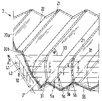
Fig. 2 an edge zone which has been reshaped in accordance
with the method in accordance with the invention,
Fig. 3 the cross-sectional profile of a roller pair,
Fig. 4 the lower roller of the roller pair of Fig. 3 with two axially
arranged reshaping parts,

'~ CA 02299088 2000-02-22
-3-
Fig. 5 a reshaped edge zone of a film, the reshaping of which
has been executed in three reshaping steps,
Fig. 6 a side view of the film of Fig. 5 with an illustration of the
change of geometry in the three reshaping steps and
Fig. 7 a fragment of a film which has a furrowing as well as a
perforation.
The plant which is illustrated in Fig. 1 comprises the following
components: a device 10 for continuously forwarding a film strip 2 from
a non-illustrated film supply to shaping units 11, 12, 12', 12"; a first
shaping unit 11 for pleating the film strip 2, with a corrugated or zigzag-
shaped film strip 2' being formed; three shaping units 12, 12', 12" for
reshaping the film strip 2' by means of a roller pair 120 in each case;
apparatuses 13 for drawing off the shaped film strips 2' and 3. The
pleating can be carried out with a pair of gear-like rollers or through
pressing with an oscillating tool 110. Details of the procedure of
pleating (or "inclined pleating") can be found in EP-A 0 739 846
(=P.6670) .
Fig. 2 shows a part of a pleated film strip 3 which has resulted from a
film strip 2' through the reshaping of an edge zone 30b of width R. A
second edge zone, which is likewise reshaped, does not appear in the
drawing. Only a middle zone 30a or a part of this zone is illustrated.
The original pleating of the film strip 2' is present in the middle zone
30a with straight, parallel edges 21, 22. In the edge zone 30b the
original pleating is indicated in chain-dotted lines. An outer cut edge 35

'' '' CA 02299088 2000-02-22
-4-
of the edge zone 30b extends parallel to a non-illustrated edge of the
film strip 2'. The edges 21, 22 subtend an angle of inclination cp to a
straight line 33 which extends parallel to the cut edge 35. Edges 31, 32
of the edge zone 30b which lie on curved paths form variable angles of
inclination which are formed by the tangents at the named curves and
the straight line 33. These variable angles of inclination increase
continuously from the middle zone 30a to the strip edge (or cut edge
35).
The film strip 3 has a height h; this yields the layer widths of a packing
with a cross channel structure which is produced from pieces of the film
strip 3 and through a layered construction.
For the explanation of the reshaping the edge zone 30b in Fig. 2 is
subdivided into a plurality of strips which correspondingly subdivide a
disc-like volume of height h and width R into bar-shaped partial
volumes 41, 42, ... . It is illustrated for an edge 21 or 31 respectively by
arrows 5a and 5b which are associated with the partial volumes 41, 42,
... how individual surface elements of the horizontally lying film 2' are
vertically displaced during the reshaping. The lengths of the arrows 5a
and 5b show qualitatively how large the displacements of the surface
elements are; these lengths are approximately proportional to the paths
travelled during the displacements. Through a plastic deformation
which is carried out by means of a roller pair the edges 21 of the
original pleating are eliminated (arrows 5a) and replaced by curved
edges 31 (arrows 5b). The elimination of the edge 21 and the new
formation of the edge 31 which takes place adjacently occur practically

'' CA 02299088 2000-02-22
-5-
simultaneously.
Fig. 3 shows a cross-section through the upper roller 121 of the roller
pair 120. The tooth profile of the lower roller 122 is illustrated in chain-
dotted lines. Between the two rollers 121 and 122 there is a settable gap
123 which is set according to the thickness of the film 2'. The directions
of rotation are illustrated by the arrows 61 and 62.
The rollers 121, 122 can be manufactured from a large number of
lamella by means of which the roller profile can be formed in a simple
manner instead of from a solid piece. All lamella have in each case a
same gear profile. Adjacent lamella are arranged adjacently with a
displacement by angles, with the angles being determined by the
required shape of the roller profiling and the lamella thickness.
The rollers 121 and 122 respectively advantageously comprise two
axially arranged reshaping parts 122a and 122b on a drive shaft 124:
see Fig. 4, in which the lower roller 122 of Fig. 3 is illustrated. Each
reshaping part 122a and 122b receives a reshaping profile 130b for
reshaping the edge zones 30b (width R) and a profile 130a which
engages without reshaping into the profile given by the pleating of the
film strip to be processed. Between the reshaping parts 122a and 122b,
which are secured to a cylindrical carrier body 124', there is a ring
groove with settable groove width b. The reshaping is carried out at a
set groove width b for which the reshaped film strip 3 is held within the
reshaping profile in spite of a transverse expansion of the edge zones.
This transverse expansion, which can amount to about 1 to 3 mm,
arises as a result of the plastic deformation. The groove width b is

26380-60 ~ 02299088 2003-09-24
6
preferably set in such a manner that when emerging from the
roller pair 120 the film edges 36 (see Fig. 5) come to lie
on the outer edges 125 of the reshaping profile 130b so that
the roller width B is thus just as large as the width of the
film strip 3 after the reshaping. For setting the width B
the carrier body 124' and connecting means between this
carrier body 124' and the reshaping parts 121, 122 are
constructed suitably. The width B is expediently increased
in that the two reshaping parts 121, 122 are displaced in
opposite directions along the arrows 6a and 6b shown in Fig.
4.
At the exit of the roller pair 120 the film strip
3 must be guided at the edges in such a manner that a
movement of the strip 3 transversely to the forwarding
direction is prevented.
Fig. 5 shows the edge region of a film strip 3,
which is manufactured by means of three reshaping steps from
a pleated film strip 2' (edges 21 and 22 in chain-dotted
lines). As soon as an edge 31 which is formed during the
reshaping and which lies upwardly crosses an adjacent edge
21 of the original film strip 2' which likewise lies
upwardly, at the point 7, then at least a second reshaping
step is necessary. For each reshaping step however only two
directly adjacent edges 21 (lying upwardly) and 22 (lying
downwardly) can be reshaped at the same time. Since in the
illustrated example the edge 31 crosses two adjacent
upwardly lying edges 21, namely at the points 7 and 8, a
total of three reshaping steps is required.
In the reshaping steps a zigzag profile of the
strip edge 36 is displaced successively to the right: see
Fig. 6. In the uppermost partial figure the

CA 02299088 2000-02-22
_7_
edge 36' of the not yet reshaped film strip 2' is shown. The second
partial figure shows the displaced zigzag profile after the first reshaping
step. The horizontal arrow 81 indicates how the edge 21 appears anew
as the edge 31'. The vertical arrows 5 indicate how surface elements are
displaced upwardly or downwardly as a result of the reshaping. The
arrows 82 and 83 represent the further displacements of the edges 31'
and 31" respectively in the second and third reshaping step, with the
edge 31" merging into the edge 31 in Fig. 5 in the third step.
In the last reshaping step the edge zone 30b is designed in such a
manner that the angle of inclination at the film edges 36 is greater than
80° and such that it preferably amounts to 90°.
In the pleating a value in the range from 20° to 70° can be
chosen for
the angle of inclination cp of the film strip 2'. Films can be used which
have a fine structuring for example in the form of a furrowing and/or a
perforation for example through holes which are arranged in a grid-like
manner. Fig. 7 shows a corrugated film with a furrowing 37 which is
formed by crossing furrows. This film is also perforated by holes 38
which are arranged in a grid-like manner. The reshaping which is
carried out in the method in accordance with the invention leaves a
given fine structuring largely intact.

Representative Drawing
A single figure which represents the drawing illustrating the invention.
Administrative Status

2024-08-01:As part of the Next Generation Patents (NGP) transition, the Canadian Patents Database (CPD) now contains a more detailed Event History, which replicates the Event Log of our new back-office solution.

Please note that "Inactive:" events refers to events no longer in use in our new back-office solution.

For a clearer understanding of the status of the application/patent presented on this page, the site Disclaimer , as well as the definitions for Patent , Event History , Maintenance Fee  and Payment History  should be consulted.

Event History

Description Date
Time Limit for Reversal Expired 2017-02-22
Letter Sent 2016-02-22
Inactive: IPC from MCD 2006-03-12
Grant by Issuance 2004-08-10
Inactive: Cover page published 2004-08-09
Inactive: Final fee received 2004-05-28
Pre-grant 2004-05-28
Notice of Allowance is Issued 2003-12-22
Letter Sent 2003-12-22
Notice of Allowance is Issued 2003-12-22
Inactive: Approved for allowance (AFA) 2003-12-03
Amendment Received - Voluntary Amendment 2003-09-24
Inactive: S.30(2) Rules - Examiner requisition 2003-03-31
Application Published (Open to Public Inspection) 2000-10-15
Inactive: Cover page published 2000-10-15
Letter Sent 2000-04-17
Inactive: Correspondence - Transfer 2000-04-06
Inactive: IPC assigned 2000-04-04
Inactive: First IPC assigned 2000-04-04
Inactive: Courtesy letter - Evidence 2000-03-21
Filing Requirements Determined Compliant 2000-03-17
Inactive: Filing certificate - RFE (English) 2000-03-17
Application Received - Regular National 2000-03-15
Inactive: Single transfer 2000-03-09
Request for Examination Requirements Determined Compliant 2000-02-22
All Requirements for Examination Determined Compliant 2000-02-22

Abandonment History

There is no abandonment history.

Maintenance Fee

The last payment was received on 2004-01-16

Note : If the full payment has not been received on or before the date indicated, a further fee may be required which may be one of the following

  • the reinstatement fee;
  • the late payment fee; or
  • additional fee to reverse deemed expiry.

Please refer to the CIPO Patent Fees web page to see all current fee amounts.

Owners on Record

Note: Records showing the ownership history in alphabetical order.

Current Owners on Record
SULZER CHEMTECH AG
Past Owners on Record
BAR MARTIN
Past Owners that do not appear in the "Owners on Record" listing will appear in other documentation within the application.
Documents

To view selected files, please enter reCAPTCHA code :


To view images, click a link in the Document Description column. To download the documents, select one or more checkboxes in the first column and then click the "Download Selected in PDF format (Zip Archive)" or the "Download Selected as Single PDF" button.

List of published and non-published patent-specific documents on the CPD .

If you have any difficulty accessing content, you can call the Client Service Centre at 1-866-997-1936 or send them an e-mail at CIPO Client Service Centre.


Document
Description 
Date
(yyyy-mm-dd) 
Number of pages   Size of Image (KB) 
Representative drawing 2000-10-06 1 14
Claims 2003-09-24 3 113
Description 2003-09-24 7 284
Description 2000-02-22 7 286
Abstract 2000-02-22 1 24
Drawings 2000-02-22 4 115
Claims 2000-02-22 3 115
Cover Page 2000-10-06 1 42
Representative drawing 2004-07-07 1 18
Cover Page 2004-07-07 1 46
Courtesy - Certificate of registration (related document(s)) 2000-04-17 1 113
Filing Certificate (English) 2000-03-17 1 163
Reminder of maintenance fee due 2001-10-23 1 112
Commissioner's Notice - Application Found Allowable 2003-12-22 1 160
Maintenance Fee Notice 2016-04-04 1 169
Correspondence 2000-03-17 1 14
Correspondence 2004-05-28 1 29