Note: Descriptions are shown in the official language in which they were submitted.
CA 02299106 2000-02-22
INJECTOR/VALVE COMBINATION DESIGNED TO IMPROVE
COLOR DOSING RESPONSE TIME
Field of the Invention
This invention relates to an improved injector/valve combination which
permits nearly immediate response time to an actuator signal. Such a
combination is
particularly suited for injecting colorants into polyurethane slabstock foam
and
permits a substantial reduction in foam waste due to low colorations during an
on/off
cycle. Specifically, this invention combination comprises a novel ball valve
which
allows for instantaneous shut-off and -on without appreciable leakage or
pressure drop
and without the need to utilize a high throughput flow rate. Such a ball valve
is used
in combination with an injector which is actually attached to the valve, the
configuration which permits continuous use and instantaneous on/off without a
deleterious pressure drop and minimizes the possibility of turbulence as. the
liquid
polymeric colorant flows through the injector. The ball valve, the attached
injector
configuration, the coloring apparatus comprising the inventive ball valve
and/or the
attached injector configuration, and the slabstock foam colored through the
utilization
of such an apparatus are also contemplated within this invention.
Background of the Invention
The demand for a wide variety of colors in polyurethane slabstock foam has
resulted in a significant move to blend-on-fly color dosing units based on the
use of
CA 02299106 2000-02-22
2
polymeric colorants. In this case color metering equipment is used to
accurately dose
two or more colors that are injected into the polyol stream and subsequently
mixed in
the foam mixhead to provide the correct shade and depth of color. The biggest
advantage of this type of approach is that now an unlimited number of colors
can be
made from 4 or 5 "primary" colors. In addition, changes from one dark color to
the
next can usually accomplished in relatively short distances minimizing the
amount of
foam that must be scrapped as a result of the color change. Light shades have
proven
to be more of a challenge since the. color throughput is substantially lower
causing the
response time to increase before changes actually made in the system can take
effect.
A means was needed to reduce this response time to an acceptable level thus
minimizing the length of time required to change from one color to the next
even at .
flow rates (approaching 2 grams per minute or less.) To do this it was
necessary to
design a unique 3-way valve/injector system that minimized the volume between
the
injection port and the recirculation line. This results in a rapid build up of
pressure
and hence almost instantaneous feed when switching from recirculation to
dispense
mode. In addition to rapid initiation of color flow it also required that flow
be almost
instantaneously interrupted even at high throughput when the color was
switched from
dispensing mode back to the recirculation mode. This is to prevent the
"bleeding" of
color back into the manifold when the need for color ends. The near immediate
start
and stop of color flow has been accomplished as a result of the current
invention.
Polymeric colorants (i.e., polyoxyalkylenated colorants) such as those
CA 02299106 2000-02-22
3
described in U.S. Patent 4,284,279 to Cross et al., herein entirely
incorporated by
reference, have been used for a number of years to color polyurethane
slabstock foam
(i.e., in a continuous process). Prior to the utilization of such polymeric
colorants,
pigment dispersion were the main source of polyurethane coloring compounds.
Such
dispersions have traditionally proven very difficult to handle, too viscous
for use
within standard injectors, highly staining and thus difficult to clean from
standard
injector equipment (without the need for environmentally unfriendly solvents),
and
very abrasive and thus potentially damaging to the delicate machinery
associated with
coloring slabstock polyurethane foam. As a result, polymeric colorants are
widely
accepted as the best materials for coloring polyurethane foam.
In the past, custom blends of polymeric colorants were made ahead of time
using two or more "primary" colors prior to incorporation within the target
foam. The
components would be mixed together using some typed of agitation such as mixer
or
drum tumbler. Once the blend was of an appropriate shade it was transferred to
a
storage tank for further introduction within the foam substrate. Upon
completion of
coloring with a specific batch of polymeric colorant, the previously run color
would
have to be emptied from the storage tank; the tank would need to be cleaned;
and then
the next color to be run in the same tank would have to be charged in the
tank.
Cleaning of the tanks, pipelines, etc., was facilitated due to the water-
solubility of the
polymeric colorants (particularly as compared to pigments); however, the
procedures
followed were still considered labor intensive and not cost efficient. The
general
CA 02299106 2000-02-22
4
practice was then modified to maintain a dedicated tank for each separate
color
(shade) that was to run. This led to a number of inefficiencies and
limitations that
were not desirable if a foam manufacturer was to adequately meet demands in
the
market place.
Polymeric colorants such as those cited above in Cross et al. were designed
to_
be totally miscible with one another as well as with most polyols, one of the
two main
ingredients used to produce polyurethane materials (isocyanates being the
other).
Pigment dispersions, on the other hand, are particulates dispersed in some
type of
liquid carrier. They require a high degree of agitation before they
satisfactorily blend
together to provide a uniform color. As a result the short amount of time that
the
polyol and colorant are mixed in the typical slabstock foam machine's mixhead
is not
sufficient to produce in an adequate mixture of components to insure a single,
homogeneous coloration throughout the target foam. Thus, another modification
was
made permitting separate addition of desired polymeric colorants within a
polyol
manifold for subsequent blending as the polyol/isocyanate mixture passes
through the
mixhead. As a result, well over half of all the colored slabstock foam is
produced in
the United States through such a method.
A configuration of this new (now typical) polymeric colorant production line
for slabstock foam is depicted in FIG. 1. This new coloring system itself
generally
consisted of 4 to 6 "primary" color storage tanks (one of which is depicted as
10 in
FIG. 1) each feeding color to at least one positive displacement spur gear
pump 12
CA 02299106 2000-02-22
coupled to a variable speed motor/drive 14 (such as available from Viking).
The
motor/pump combination 12, 14 was typically run continuously in either
recirculation
or dispense mode (depending on the position of a 3-way valve 16) to minimize
the
time required to spool up the motor 14 to the proper rpm and to ultimately
achieve the
pressure required to initiate color flow into a pre-mix manifold 18 through an
injector
20. The throughput pressure was typically measured through the utilization of
a
pressure gauge 25 attached to the feed line 13 from the pump 12 to the 3-way
valve
16. The typical 3-way valve 16 was air actuated and used to direct the flow of
colorant from the recirculation feed line 22 to the dispense feed line 24 (to
the injector
20) when color flow to the manifold 18 was required. From the manifold 18, the
colorants) was moved to the mixing head 26 and then further on to color the
target
slabstock foam (not illustrated). Although this configuration has proven
effective in
the past, there remain a number of problems associated with this procedure
which
have heretofore been unresolved.
For instance, the market place demands that a foam producer be able to
provide dark shades as well as light shades with a variety of hues and polyol
flow
rates. Since color is metered volumetrically a wide range of color flow rates
are
required to insure low enough flow for a minor component in a light shade. In
addition, the polyol flow rates can be as low as 10 kg/min and as high as 300
kg/min
[color loading is generally stated in parts per hundred polyol (php)]. As the
rate at
which the polyol flows is reduced so must the color rate be reduced to
maintain the
CA 02299106 2000-02-22
6
same php. For most foams manufactured.in the United States the color delivery
systems must be able to provide color flow as low a 2 grams/min and as high as
7000
grams/min or more. The rate at which color begins to flow when pumping 5000
grams/minute is generally very different than pumping 5 grams/min until the
present
invention is incorporated. Prior to this point the general approach was to use
a smaller
diameter line for the low flow range. Unfortunately, there are distinct
limitations on
such a small diameter (small bore) feed line, most notably the resultant
throughput
pressure drop from pumping material several feet through a small diameter
line.
Furthermore, the typical polyurethane slabstock foam coloring system has a
three-way air actuated ball valve (28 in FIG. 2) that is positioned up near
the polyol
manifold. Due to the configuration of the available ball valves they are
generally
located approximately 1 meter from the manifold. As provided by the
representation
of a standard three-way ball valve assembly in FIG. 2, material metered by the
pump
enters the top of the three-way ball valve 27 from the storage tank feed line
29 and
exits either through the recirculation side 30 or the dispense side 32
depending on how
the ball is oriented. FIG. 2 depicts the ball valve 27 when it is oriented in
the
recirculation mode. Once it is desired to change from recirculation to
dispense and
back to dispense the ball valve 28 must typically rotate 180 ° from one
side of the
valve to the other (although there are some apparati which utilize a 90
° ball valve
rotation) through the movement of an actuator (not illustrated) attached to an
actuator
pin 34 which, in turn, fits into an identation (not illustrated) within the
ball valve 27.
CA 02299106 2000-02-22
Furthermore, the typical ball valve 28 comprises a single channel 31 to
accommodate
the flow of colorant to either the recirculation side 30 or the dispense side
32. This
single channel is configured at a right angle and thus may contribute to
laminar flow
problems by requiring the colorant liquid to radically change direction,
thereby
altering the pressure over the total liquid mass (and thus producing non-
uniformity of
pressures over the entire liquid colorant).
In addition to this 3-way valve, a device must be used to inject color away
from the wall of the manifold to insure adequate subsequent mixing (i.e., to
reduce the
problems associated with laminar flow through a feed line having a larger
diameter
than the 3-way valve. Ideally, such a device should function as a check valve
to
maintain pressure in the line and to stop color flow when switching from
dispense to
recirculation. Such devices must maintain pressure after the dispensing unit
is
returned to recirculation mode otherwise the pressure drops below the
"cracking"
pressure of the check valve spring which will result in even longer startups
which, in
turn, may translate in to cost overruns or potentially greater amount of off
quality
colored foam. Additionally, the resultant pressure drop must be acceptable
across a
broad delivery range for such injectors to alleviate any other related
pressure
difference problems.
An entire colorant pumping system (such as discussed with regard to FIG. l,
above) was developed to evaluate a variety of injection systems that closely
resembles
an actual production unit. It consisted of a spur gear pump from Viking
coupled with
CA 02299106 2000-02-22
8
a full flux vector motor and drive from Baldor. Stainless steel tubing having
an
outside diameter of ~/a inch was connected to the discharge side of the pump.
The
distance from the pump to the 3-way valve was approximately 40 feet. The
distance
from the standard 3-way valve to the check valve was 3 feet. The motor/pump
was
run to insure pressure up through the 3 way valve and then it was allowed to
dispense
to insure that fluid filled the line under pressure from the valve to the
check valve.
Measurements were then taken of the time required from the moment the 3-way
valve
is switched from recirculation to dispense and the time that a liquid
polymeric
colorant actually began to flow at various throughputs. Colorant response time
(the
time required for colorant to begin to flow from the three-way valve to the
injector)
was compared with throughput flow rate for this well known system. The results
are
tabulated below:
TABLE
Colorant Response Time f seconds) Flow Rate ( /g mint
48 2.5
15 4
5 20
3 42
0 86
Thus, at low throughput flow rate, the time before delivery becomes excessive.
It initially took 48 seconds from the time the valve was rotated until color
began to
flow at 2.5 grams per minute. This would represent almost 14 feet of off
quality foam
CA 02299106 2000-02-22
9
generated with the conveyor speed of 17 feet per minute or a loss of up to 700
lbs of
foam making chemical that would be disposed of as scrap. Obviously, an
instantaneous delivery was needed for all flow rates which has not been
accorded the
industry by the prior art.
Description of the Invention
It is thus an object of the invention to provide a ball valve within a
colorant
injector apparatus which allows for instantaneous switching from a
recirculating
component to dosing to the injector without requiring a high throughput
pressure.
Another object of this invention is to provide an apparatus for coloring
polyurethane
slabstock foam which comprises a unitary injector/valve assembly. A further
object
of the invention is to provide a low throughput flow rate method of coloring
polyurethane slabstock foam with a colorant injection which substantially
reduces and
possibly eliminates the production of off quality, improperly colored waste
foam
materials. Another object of the invention is to provide a significant
improvement in
coloring polyurethane slabstock foam over the prior art through the
utilization of a
two-channeled ball valve which allows for instantaneous on/off performance at
a very
wide range of throughput pressures. Yet another object of this invention is to
provide
an injector/valve assembly which substantially reduces the problems associated
with
laminar flow of liquid colorants or pigment dispersions in a coloring
apparatus by
permitting introduction of the colorant material away from the walls of the
manifold
CA 02299106 2000-02-22
thereby limiting the potential for deleterious turbulence (and thus
potentially
problematic resistance and pressure changes through the entire system).
Accordingly, this invention provides a spherical ball valve having first and
second channels;
5 wherein each channel is exclusive of the other;
wherein said first channel has a first opening and a second opening, both of
which are
located at different locations on the spherical ball valve surface; and
wherein said second channel has a first opening and a second opening, both of
10 which are
located at different locations on the spherical ball valve surface. Also, this
invention
provides for an injector/valve combination comprising such a spherical ball
valve.
Furthermore, this invention provides for an injector/valve combination wherein
said
valve comprises a ball valve and said injector is placed at a location within
very close
proximity to the valve. By the term "very close proximity" it is meant that
the two
components are attached, either permanently or temporarily, to each other (by
a screw
mechanism, for example), or that the two components are within at most about
12
inches away from each other. The greater the distance between the three-way
valve
and the injector, the greater potential for leak problems (which may result in
off
quality foam production and undesirable pressure changes, as examples), as
well as
the greater possibility for longer colorant response times, as discussed
above.
CA 02299106 2000-02-22
Preferably, the valve and injector are corr~bined in a unitary assembly.
however, as
noted above, relatively short spatial distances may be employed between these
two
components. In such instances, a pipe, which is preferably straight, must be
utilized
to connect the two components which itself must have the same bore size as the
ball
valve channel and the injector. Additionally, a method of coloring slabstock
polyurethane foam utilizing a colorant apparatus comprising such an
injector/valve
combination as discussed above, and the resultant colored slabstock
polyurethane
foam are encompassed within the instant invention. The term "slabstock
polyurethane
foam" is a well known description of cured polyurethane foam, made from the
reaction of polyols and isocyanates, which is uncolored and fed through a
coloring
apparatus in its bulky foamed state.
The instant invention solve the problems outlined above. A special 3-way
valve was developed that comprises two exclusive channels that allows the
valve to
dispense from the bottom rather than feed from the bottom. In doing so the
check
valve was then connected directly to the bottom of the valve that would
minimize the
distance between the 3-way valve and manifold. In addition, a special
"injector" was
developed introducing color away from the wall of the manifold. This valve/inj
ector
configuration was tested in a similar manner as the standard configuration.
The
results was instantaneous flow regardless of the flow rate. In addition, due
to the
close proximity of the 3-way valve to the actual injection point, even if the
injector
leaked the volume is so small that it quickly filled again to the point that
it would
CA 02299106 2000-02-22
12
depress the injector spring (or bevelled washers) allowing instantaneous flow.
Thus, two very important discoveries have been made with this invention
which permit a substantial reduction in waste of slabstock foam (thereby
reducing
costs to the end user and reducing the amount of environmentally unfriendly
off
quality polyurethane foam entering landfills, and the like). First, the
specific ball
valve (which is a spherical ball valve) configuration discussed above
facilitates an
instantaneous on/off switching between a dispensing feed line to an injector
unit and a
feed line to a recirculation assembly (to reduce the amount of colorant
potentially
wasted and to best insure the throughput pressure of the entire apparatus
remains
uniform at all times). In particular, this ball valve comprises two exclusive
channels,
one of which is positioned to direct the flow of colorant to the recirculation
assembly
and the other to direct such a flow to the injector. This is accomplished by
having the
two separate channels be aligned on totally separate axes (for instance,. one
on the x-
axis and the other on either the y- or z-axis). More specifically, the channel
not on the
x-axis must enter the spherical ball valve at a point referenced as 0 °
on the particular
axis and exits the spherical ball valve at a point 90° on the same
axis. In this manner,
the two channels are completely exclusive of another, thereby facilitating
movement
of the valve between recirculation and dispensing modes. Furthermore, the
configuration of the non-x-axis channel reduces the change of pressure on the
liquid
colorant through the valve than with a standard right angle bending channel
(it
provides a sort of shunt). Such a ball valve has proven to be invaluable in
providing
CA 02299106 2000-02-22
13
the necessary instantaneous on/off (color response) times as well as
maintaining the
proper flow rate (at an extremely wide range from about 0.3 g/min to about
14,000
g/min).
An actuator is utilized, generally, to rotate this ball valve into these
specific
positions. Such an actuator includes a pin extending into the valve assembly,
the end
of which pin is shaped to fit an indentation in the ball valve. The actuator
then turns
the ball valve the requisite number of degrees to align the respective channel
to the
desired feed line (90° is preferred, although, in some instances,
180° may be
possible).
The second discovery with this invention has been that the valve assembly and
injector unit can be moved in close proximity of one another in order to
provide
substantial reductions in waste foam production as well. In fact, a unitary
assembly of
the valve and injector is preferred, particularly where the injector itself is
positioned in
direct contact with the manifold of the coloring apparatus. Such close
proximity
requirement is significant since the apparati known in this industry all have
injectors
which are spaced a considerable distance from the dosing valve. The prior art
dosing
valves basically perform the fiznction feeding the colorant either to the
injector or to
the recirculation line; however, in all known instances, this three-way valve
(from the
colorant tank to either the injector or the recirculator), is necessarily
positioned a great
distance from the injector (about 3 feet on average) due to previously
believed
configuration problems. No other previously used or described ball valve
permitted a
CA 02299106 2000-02-22
14
trustworthy instantaneous on/off function in order to best guarantee off
quality foam
would not be produced. Thus, the three-way valve and injector have
traditionally
always remained separated by a substantial length of flexible pipe. Although
such an
apparatus has proven to work well in the past, there has been no mechanism to
reduce
the amount of waste slabstock foam without resorting to the utilization of
relatively
high pressures or flow rates. For instance, color variations in the resultant
foam
products occur with regularity in the standard coloring assemblies when the
pressure
between the pump and the three-way valve is significantly increased in order
to reduce
colorant response time (the time required to move the colorant from the three-
way
valve to the manifold). This is caused by pressure differences between the
area
between the pump and the valve and the valve and the manifold and the fact
that
polymeric colorants exhibit slight degrees compressibility which are not
properly
accounted for in the standard slabstock foam coloring assemblies. Since such
colorants may be transported to the valve at an abnormally high flow rate to
the
injector (while the dispense feed line has not been in use and thus may
exhibit a lower
amount of pressure), the overall colorant flow rate may oscillate to an
abnormally low
rate (to compensate for the pressure existing between the valve and the
manifold)
prior to its ultimate stabilization. This may require minutes of stabilization
time
which, again, may result in minutes worth of waste off quality foam product.
Furthermore, waste (off quality) foam production has been caused by delayed
colorant
flow (throughput flow rate), pressure drop, and turbulence problems, as noted
above,
CA 02299106 2000-02-22
which themselves are attributed to varying bore sizes between the three-way
valve, the
colorant dispensing feed line (to the injector), and the injector within
standard
polyurethane slabstock foam coloring apparati. Additionally, the standard
three-way
valves utilize ball valves comprising single channels for directing colorants.
In
5 general, these channels are formed in such a way to require a right angle
turn of the
colorant liquid through the valve assembly either to the injector feed line or
to the
recirculator pipeline. Such a change of direction potentially increases the
laminar
flow problems associated with the movement of liquid colorants through feed
lines
(since the flow of discrete portions of the liquid material will not be
substantially
10 uniform) and can subsequently result in deleterious pressure changes which,
again,
can result in off quality foam production.
The inventive ball valve and injector/valve assembly have provided a means to
avoid all of these problems and potentially damaging circumstances,
particularly
where the bore size of the channels of the ball valve and the feed line
through the
15 injector and to the manifold are also substantially the same. Thus, the
invention
permits a substantial reduction (almost total elimination) of waste foam upon
the
utilization of very low, but highly desirable, flow rates and also allows for
the
utilization of an extremely wide range of flow rates without an appreciable
pressure
drop through the entire apparatus.
CA 02299106 2000-02-22
16
Brief Description of the Drawings
FIG. 3 is a schematic cross section of the preferred spherical ball valve
sliced
through its y-axis.
FIG. 4 is a schematic cross section of the preferred injector/valve
combination.
FIG. 5 is a diagram of the preferred coloring procedure utilizing the
preferred
injector/valve combination and the preferred spherical ball valve.
Detailed Description of the Drawings Including Preferred Embodiments
The spherical ball valve 40 of FIG. 3, which may be made from stainless steel
(preferably), titanium, carbon steel, and the like, comprises a first channel
42 which
runs through the entire sphere on one single axis (the x-axis, for instance)
and at a
specific. angle (such that the entire channel 42 is located at 0° on
the x-axis). The ball
valve 40 also comprises a second channel 44 which runs through the entire
sphere on
one single axis exclusive of the first channel 42 (here the y-axis although
the z-axis is
also possible) and at a specific angle (such that the channel 44 enters the
ball valve 40
at a point at approximately 0 ° on the sphere in the y-axis and exits
the ball valve 40 at
a point 90° from the other entry but still in the same axis. Through
this configuration,
the first channel 42 permits flow of the liquid colorant (not illustrated)
through the
valve 40 to a recirculation feed line (58 of FIG. 4) when aligned with the
inlet feed
line (52 of FIG. 4) from a storage tank (72 of FIG. 5). Upon rotation of
90°by the
CA 02299106 2000-02-22
17
utilization of a actuator pin (60 of FIG. 4) attached to an actuator (62 of
FIG. 4)
engaged with a properly shaped indentation (not illustrated) located at the
point 270 °
on the y-axis in and of the ball valve 40, the first channel 42 is disengaged
from all of
its corresponding feed lines (52, 58 of FIG. 4) and permits the flow of liquid
colorant
(such as polymeric colorants, not illustrated) through the ball valve 40 (43
of FIG. 4)
and into the dispensing feed line (64 of FIG. 4). The bore of each channel 42,
44 is
the same for each; however, the actual size of both bores in said channels 42,
44 may
be of any size as long as they are the size as the bore of the inlet feed line
(52 of FIG.
4), the recirculation feed line (58 of FIG. 4), and the dispensing feed line
(64 of FIG.
4). The ball valve 40 (43 of FIG. 4) size is merely dependent upon the amount
of
space between all of the feed lines (52, 58, 64 of FIG. 4) within the entire
valve
assembly (41 of FIG. 4). The dispensing feed line (64 of FIG. 4) permits the
flow of
the liquid colorant (not illustrated) into the injector (66 of FIG. 4) which
itself
possesses the same size bore as the ball valve 40 and the feed lines (52, 58,
64 of FIG.
4). The injector (66 of FIG. 4) may be attached to the valve assembly 41 by
way of a
screw mechanism (not illustrated), in which case a straight screw (not
illustrated) is
preferably and beneficially utilized in conjunction with a rubber gasket (68
of FIG. 4)
thereto attached. However, the injector (66 of FIG. 4) may also be welded, or
the
like, to the valve assembly 41 as well.
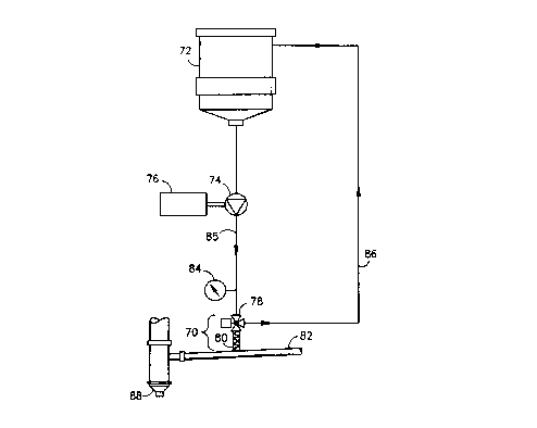
FIG. 5 thus incorporates the preferred injector/valve combination (70 of FIG.
4) into the entire slabstock foam coloring apparatus and procedure. The
colorant is
CA 02299106 2000-02-22
18
transported from a storage tank 72 to at least one positive displacement spur
gear
pump 74 coupled to a variable speed motor/drive 76 (such as available from
Viking).
The motor/pump combination 74, 76 is run continuously in either recirculation
or
dispense mode (depending on the position of the 3-way valve 78). In dispense
mode,
the colorant flows through the injector 80 into a pre-mix manifold 82. The
throughput
pressure is measured through the utilization of a pressure gauge 84 attached
to the
feed line 85 from the pump 74 to the 3-way valve 78. The 3-way valve 78 is air
actuated (although any other type of actuator may be used) and and directs the
flow of
colorant from the recirculation feed line 86 to the dispense feed line to the
injector 80)
when color flow to the manifold 82 is desired. From the manifold 82, the
colorant is
moved to a mixing head 88 and then further on to color the target slabstock
foam (not
illustrated).
There are, of course, many alternative embodiments and modifications of the
present invention which are intended to be included within the spirit and
scope of the
following claims.