Note: Descriptions are shown in the official language in which they were submitted.
, CA 02299194 2000-02-23
1
ROOF CONSTRUCTION
BACKGROUND OF THE INVENTION
This invention concerns roof construction and, in particular, concerns
glazed roof construction, such as for forming a conservatory.
Conservatory roofs are generally formed from glazing panels supported
between glazing bars fixed between a ridge beam and an eaves beam or other
side supporting structure, such as a window frame. The glazing bars are
usually
of aluminium and screws are used to fix the glazing bars to the supporting
structure. A difficulty with the use of screws directly through glazing bars
is that
they can slip as they are being screwed in. That creates particularly
difficulties
when screwing down ducted glazing bars when the screws are fixed into and
through the ducts. Putting the screws through the ducts is better for
concealment and neatness but is more difficult practically.
Another problem with the use of screws directly through glazing bars into
a supporting structure is that of cold transference where the glazing bars
supporting structure component and the screws are all of metal. When the
outside of the conservatory roof is colder than the inside, cold spots and
hence
condensation can form on the inside of the roof.
The above problems arise whether the glazing bar is of a type that
supports glazing panels on opposite sides thereof or of the type that acts as
CA 02299194 2000-02-23
2
reinforcement between glazing panels coupled to each other andlor to the
glazing bars.
SUMMARY OF THE INVENTION
An object of this invention is to provide an improved glazed roof
construction particularly for use in forming conservatory roofs.
According to this invention it is proposed that a fixing block be mountable
at a glazing bar end wherein the fixing block has provision for receiving and
directing a fixing screw used to secure the fixing block and hence the glazing
bar
to a support structure, such as an eaves beam or a window frame.
The invention also provides a glazed roof wherein glazing bars supporting
glazing panels are secured to a supporting structure by means of screws
through fixing blocks mounted at the glazing bar ends, the fixing blocks
having
provision for receiving and directing the fixing screws.
The fixing blocks are preferably of plastics material, especially PVCu.
The fixing blocks are preferably arranged to be a push fit onto glazing bar
ends.
For a glazing bar that has a single webbed upstand, the fixing block
preferably
has formations that will sit on either side thereof but for a ducted upstand
glazing
bar it is preferred that fixing blocks have a formation that is a push fit
into the
duct of the glazing bar.
The fixing block of the invention preferably has a through hole for
receiving and guiding a screw, the through hole preferably being angled to
direct
a screw downwardly and towards the roof interior. The through hole is
CA 02299194 2000-02-23
3
preferably stepped intermediate its ends to provide a stop for the screw head.
The fixing block of the invention preferably has on its outer end relative to
a glazing bar a pair of wings extending laterally. Those wings are intended to
act as abutments for glazing panels, whereby adjacent panels can be aligned
and slippage can be prevented.
The fixing block of the invention preferably also has means for attachment
of a glazing bar end cap. Preferably the glazing bar end cap is slidably
mountable on the fixing block end. The preferred fixing block has a pair of
back
to back L-shaped brackets. These may be formed by one plate spaced from the
fixing block and the glazing bar end cap preferably has a corresponding pair
of
facing L-shaped projections that can slidably fit onto the brackets of the
fixing
block.
The preferred fixing block of the invention has a top formation
corresponding to that of the glazing bar to which it is to be fitted, so that
a
capping for the glazing bar can also be supported by and/or secured to the
fixing
block in the same manner as provided by the glazing bar.
BRIEF DESCRIPTION OF THE DRAWINGS
This invention will now be further described, by way of example only, with
reference to the accompanying drawings, in which:-
Figure 1 is a partly cut away perspective view of a conservatory roof;
Figure 2 is another perspective view of the roof of Figure 1 not cut away;
Figure 3 is a section through the roof of Figures 1 and 2;
CA 02299194 2000-02-23
4
Figure 4 is a section through a variation on the roof of Figures 1 to 3;
Figures 5 and 6 show a conservatory roof gable end partly and fully
assembled.
DETAILED DESCRIPTION OF THE INVENTION
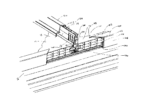
Referring to Figures 1 to 3 of the accompanying drawings, a conservatory
roof 10 comprises glazing panels 12 supported between glazing bars 14 secured
at one end to a ridge (not shown) and at the other to an eaves beam 16. The
glazing bars 14 are of a type having a ducted upstand 18 into which are push
fit
fixing blocks 20 of plastics material, typically of PVCu. The fixing blocks
have a
first part 21 that fits into the glazing bar and second part 23 that remains
outside
the glazing bar but has a similar outer profile.
The fixing blocks 20 have an angled screw receiving and guiding hole 24
which is stepped at 25 to have a narrower lower part, the step 25 forming a
stop
for the head of a fixing screw 26. The screw 26 is shown securing the fixing
block and hence the glazing bar to the head 30 of the eaves beam 16.
The eaves beam 16 is generally L-shaped having a double walled
upstand 31 and a single walled base plate 32. The base plate 32 sits on and is
secured to the underlying support structure, such as provided by window frames
34. The head 30 of the eaves beam has a generally arcuate top surface but with
a depression 38 therein. The base of the depression has a serrated or
roughened surface. Either side of the depression, the head of the eaves beam
has two alternative inner and outer areas 42 and 44 respectively on which
CA 02299194 2000-02-23
glazing bars can rest depending on the pitch of the roof. In this embodiment
the
roof illustrated has a low pitch and so the eaves beam 16 rests on the inner
area
42.
Interposed between the glazing bars and the eaves beam and lying on
the eaves beam is a thermal insulator strip 50 of plastics material. The
insulator
strip 50 snap fits onto the head 46 of the eaves beam.
The insulator strip is formed as an extrusion and has a profile generally
following the contours of the head of the eaves beam. The insulator strip is
provided with ribs 60 on its underside to space inner and outer parts 62, 64
thereof from the inner and outer areas 42, 44 of the eaves beam head, whilst a
central part 66 of the insulator strip sits in the depression in the head of
the
eaves beam. The inner and outer parts 62, 64 of the insulator strip are
provided
on their top surfaces with double-sided adhesive tape 67 in order to hold the
glazing bars 14 in place whilst they are being secured with the screws 26 to
the
eaves beam.
Extending forwardly of the insulator strip i.e. towards gutter 70 on the
outside of the conservatory is a thin resiliently flexible web 72. The web 72
contacts the underside of the glazing bar 14 or any bottom capping thereon or
the underside of the glazing panels 12 to provide a wind break.
On its inner end i.e. the end towards the inside of the conservatory, the
insulator strip has a lip 74 extending outwardly and then downwardly to form a
slot which serves as a top location for internal plastics cladding 76 for the
eaves
beam 16. The eaves beam has lower down a fir-tree connector 78 along its
CA 02299194 2000-02-23
6
length onto which a slot 80 of the cladding is a push-fit.
The eaves beam 16 supports brackets 82 for the gutter 70 and the
leading edge of the base plate 32 of the eaves beam has a push-fit trim 86
thereon, which has a flexible resilient web 88 upstanding to seal between the
underside of the gutter and the eaves beam. Furthermore, the trim has a
downstand 90 to cover profile features.
The insulator strip provides a thermal break between the glazing bars and
the eaves beam, which otherwise, both being of aluminium, would provide a
route for heat loss leading to condensation formation within the conservatory
on
the eaves beam.
Ends of the glazing panels are concealed by a channel section trim 100
having a top wall 102, a bottom wall 104 and a base wall 106. The top wall 102
has along its edge a co-extruded or bonded gasket 108 of rubber or synthetic
elastomeric material to seal against the top surface of the glazing panels.
The
bottom wall 104 is resiliently deformable to grip on the underside of the
glazing
panels. The base wall 106 has a spacing rib 110 extending therefrom as has
the top wall 112 to leave a ventilation space between the glazing panel ends
and
the trim base wall. The trim 100 will usually be supplied pre-notched 114 to
accommodate the glazing bars (see Figure 2).
The glazing panels are held down by cappings 120 that are snap-fits into
the tops of the glazing bars and of the fixing blocks whose top profiles match
those of the glazing bars. The cappings 120 have depending resiliently
deformable formations 122 that are retainable in a channel 124 in the top of
the
CA 02299194 2000-02-23
7
glazing bar having notched side walls the formations having lips that are
retained under the notches according to how far the capping is pressed down.
To conceal the ends of the fixing blocks an end cap 130 is mounted on
the fixing block. The fixing block has back to back L-shaped brackets 132 onto
which facing L-shaped flanges (not shown) of the end cap can slide downwards
until a rim 134 of the cap sits on top of the capping 120.
The fixing block 20 further has a pair of laterally extending wings 140 at
its forward end from a depending part of the block. These wings are positioned
to act as stops for the glazing panels, to position and align them. The wings
140
further act to prevent slippage of the panels in the assembled roof.
The fixing block enables the screw fixing to be accurately positioned and
guided whilst be screwed down making erection of the roof simpler than
hitherto.
Turning to Figure 4 of the drawings, instead of an eaves beam being
used, a PVCu profile 200 is mounted on the window frame 202 and it is to the
profile 200 that the fixing blocks 20 and hence the glazing bars 14 are
secured
by screws 26. Apart from that the embodiment of Figure 4 is the same as that
of
Figures 1 to 3. Like parts have been given the same reference number for ease
of reference and will not be described again.
Finally, Figures 5 and 6 illustrate the use of the fixing blocks at the gable
end of a conservatory roof 300 made up of ducted plastics panels 302 coupled
to the glazing bars 304. The fixing block and its use are the same as
described
above together with the attachment of the end cap 308 as shown in Figure 6.