Language selection

Search

Patent 2299796 Summary

Third-party information liability

Some of the information on this Web page has been provided by external sources. The Government of Canada is not responsible for the accuracy, reliability or currency of the information supplied by external sources. Users wishing to rely upon this information should consult directly with the source of the information. Content provided by external sources is not subject to official languages, privacy and accessibility requirements.

Claims and Abstract availability

Any discrepancies in the text and image of the Claims and Abstract are due to differing posting times. Text of the Claims and Abstract are posted:

  • At the time the application is open to public inspection;
  • At the time of issue of the patent (grant).
(12) Patent Application: (11) CA 2299796
(54) English Title: PINION SUPPORT
(54) French Title: SUPPORT DE PALIER
Status: Deemed Abandoned and Beyond the Period of Reinstatement - Pending Response to Notice of Disregarded Communication
Bibliographic Data
(51) International Patent Classification (IPC):
  • F16C 35/06 (2006.01)
  • B23Q 05/38 (2006.01)
  • F16C 35/12 (2006.01)
  • F16H 57/021 (2012.01)
(72) Inventors :
  • BAULIER, DOMINIQUE (Canada)
  • SOLCZ, LEONARD (Canada)
(73) Owners :
  • VALIANT CORPORATION
(71) Applicants :
  • VALIANT CORPORATION (Canada)
(74) Agent: SMART & BIGGAR LP
(74) Associate agent:
(45) Issued:
(22) Filed Date: 2000-02-23
(41) Open to Public Inspection: 2000-09-19
Examination requested: 2002-05-10
Availability of licence: N/A
Dedicated to the Public: N/A
(25) Language of filing: English

Patent Cooperation Treaty (PCT): No

(30) Application Priority Data:
Application No. Country/Territory Date
09/272,707 (United States of America) 1999-03-19

Abstracts

English Abstract


A pinion support is disclosed for use with a motor set on a gear box casing
and an output drive pinion having an axial recess at the outer end of the
pinion.
The pinion support includes a housing which is rigidly secured against
movement
to the gear box casing and includes a portion which overlies the outer end of
the
pinion. A pin is rigidly secured to the portion of the housing and this pin
extends
coaxially into the axial recess at the outer end of the pinion. A bearing
assembly
is operatively positioned between an outer surface of the pin and an inner
surface
of the pinion recess. The pinion support is particularly well suited for use
in an
automotive framing system.


Claims

Note: Claims are shown in the official language in which they were submitted.

WE CLAIM:
1. For use with a motor and gear box with an output drive pinion
having an axial recess at an outer end, a pinion support comprising:
a housing, said housing being rigidly secured against movement to the gear
box casing and having a portion which overlies the outer end of the pinion,
a pin rigidly secured to said portion of said housing, said pin extending
coaxially into the axial recess of the pinion, and
a bearing assembly operatively positioned between an outer surface of said
pin and an inner surface of the pinion recess.
2. The invention as defined in claim 1 wherein the axial recess of the
pinion is cylindrical in cross sectional shape.
3. The invention as defined in claim 1 wherein said pin is supported
by an end plate centered and secured by a grove and bolted to said housing.
4. The invention as defined in claim 1 wherein said bearing assembly
is a roller bearing assembly.
7

5. The invention as defined in claim 1 wherein said housing portion is
substantially cylindrical in shape, said housing portion having a cut out on
one
side, said cut out being open to an outer periphery of the pinion.
6. The invention as defined in claim 1 wherein the gear box casing is
rigidly mounted to a frame and wherein said housing includes a mounting flange
sandwiched between the frame and the gear box casing.
7. The invention as defined in claim 6 wherein said mounting flange
is cylindrical in shape and equipped with centering shoulder and boring.
8. The invention as defined in claim 6 wherein the frame supports a
tool rotative magazine for an automotive framing system.
9. The invention as defined in claim 1 wherein said housing portion
comprises a cylindrical section extending coaxially around the pinion, said
cylindrical section having an opening on one side, and an end plate overlying
the
outer axial end of the pinion, said pin being secured to said end plate.
10. The invention as defined in claim 9 wherein said end plate is
removably secured to said cylindrical section by bolts and grove.
8

11. The invention as defined in claim 9 and comprising a seal disposed
between said pin and the pinion recess.
12. The invention as defined in claim 11, and comprising a lubrication
channel through the pin and the end plate to lubricate the bearing.
13. The invention as defined in claim 9, and comprising a second
opening on the other side, to perform initial tightening or further checking
of
pinion clamp assembly.
14. The invention as defined in claim 13, where this second opening is
used to adapt a lubrication nozzle for the gear system (pinion and wheel
gear).
9

Description

Note: Descriptions are shown in the official language in which they were submitted.


CA 02299796 2000-02-23
PINION SUPPORT
Background of the Invention
I. Field of the Invention
The present invention relates to a pinion support for supporting a free end
of a pinion when operating in restricted room condition.
II. Description of the Prior Art
Actuator motors with gear boxes are used in many industrial applications,
such as an automotive framing system. In an automotive framing system, a motor
set on a gear box is rigidly secured to a turret frame. The motor, upon
actuation,
rotatably drives a pinion which protrudes outwardly from one end of a gear
box.
In many applications, such as an automotive framing system, the precise
rotational position of the pinion is required for accurate and satisfactory
operation
of the entire system. In many such applications, however, the pinion is
subjected
to high torque which may result in slight flexing of the pinion away from the
load.
Any such flexing not only results in unsatisfactory oscillation of the system,
but
can also result in inaccurate positioning of the load driven by the motor/gear
box,
and in some case in shaft breaking by fatigue.
Summary of the Present Invention
The present invention provides a pinion support which overcomes the
above-mentioned disadvantages of the previously known devices.

CA 02299796 2000-02-23
In brief, the pinion support of the present invention comprises a generally
cylindrical housing which is rigidly secured to the motor casing in any
conventional fashion, such as by bolts. Furthermore, in the preferred
embodiment
of the invention, the housing includes a cylindrical flange which is
sandwiched in
between a mating cylindrical flange on the motor casing and a portion of the
frame
associated with the motor/gear box.
The housing further includes a cylindrical portion which extends coaxially
around the pinion and has an end plate which overlies the outer or free end of
the
pinion. This cylindrical portion, furthermore, includes an opening along one
side
to expose the pinion and provide access between the pinion and its load, i.e.
a gear
wheel.
A cylindrical pin is rigidly fixed to the end plate and extends coaxially into
an axial recess formed on the outer end of the pinion. A bearing assembly is
operatively disclosed between the pin and the pinion recess and, preferably, a
seal
is provided between the pin and pinion recess to protect the bearing assembly
from
debris.
In operation, the rotational support provided between the pin and the
bearing assembly and the outer or free end of the pinion operates to support
the
pinion and preclude flexing of the pinion relative to the housing and thus
relative
to the gear box casing. In practice, such support not only eliminates flexing
of the
pinion during operation and radial load on output bearing, but also prevents
2

CA 02299796 2000-02-23
oscillation and vibration of the motor which can otherwise occur especially in
case
of speed or torque closed loop control, with heavy inertia.
Brief Description of the Drawing
A better understanding of the present invention will be had upon reference
to the following detailed description when read in conjunction with the
accompanying drawing, wherein like reference characters refer to like parts
throughout the several views, and in which:
FIG. 1 is an isometric view illustrating a preferred embodiment of the
present invention utilized in connection with a tooling magazine of an
automotive
framing system;
FIG. 2 is a side view illustrating the preferred embodiment of the present
invention; and
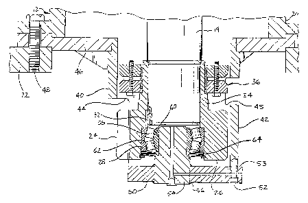
FIG. 3 is a sectional view illustrating the preferred embodiment of the
present invention.
Detailed Description of a Preferred
Embodiment of the Present Invention
With reference to FIG. 1, a portion of an automotive framing system 10 is
there shown having a turret 12 which is rotatable about a generally vertical
axis
14. In the well known fashion, tooling 16 is supported by the turret 12 to
selectively clamp an automotive body (not shown) prior to welding.
The automotive framing system 10 typically accommodates several
different models of vehicles, each vehicle having its own set of tooling 16.
In
3

CA 02299796 2000-02-23
order to position the tooling 16 at the work station, a motor 18 is
selectively
actuated to rotatably index the turret 12 about the vertical axis 14.
With reference now to FIGS. 2 and 3, the motor 18 drives a gear box 20
which is rigidly secured to a frame 22 of the framing system 10. An output or
drive pinion 24 is selectably rotatably driven by a drive shaft 19 from the
gear box
20 in order to index the turret 12 through the gear wheel 45. This pinion 24
includes an outer end 26 as well as an axial cylindrical recess 28 (FIG. 3) at
its
outer end 26.
Refernng particularly to FIG. 3, any conventional means 24 can be
employed to secure the pinion 24 to the gear box shaft 19. However, as
illustrated
in the drawing, preferably a key 32 is positioned between registering slots in
the
shaft 30 and a pinion sleeve 34. This key 32 prevents rotation of the pinion
24
relative to the gear box 19. A conventional clamp assembly 36 is then disposed
around the pinion sleeve 34 which, upon tightening, radially inwardly
compresses
the sleeve 34 against the shaft 19 thereby locking the pinion 24 to the shaft
19.
With reference now to FIGS. 2 and 3, the present invention provides a
generally cylindrical housing 40 having a cylindrical portion 42 which extends
coaxially around the pinion 24. This cylindrical portion 42 includes an
opening 44
along one side to expose the pinion 24 and enable the pinion 24 to mesh with
its
load, i.e. a gear wheel 45 (FIG. 3). The cylindrical portion 42 includes a
further
4

CA 02299796 2000-02-23
opening 45 to provide access to the clamp assembly 36 for tightening as
required.
This opening 45 can also be used to lubricate the gearing by a lubrication
nozzle.
The housing 40 further includes an annular mounting flange 46 which is
rigidly secured against movement to the gear box casing 20. Preferably, the
mounting flange 46 is sandwiched in between the motor casing 20 and the system
frame 22 and then secured together by bolts 48.
As best shown in FIG. 3, the housing 40 further includes an end plate SO
which overlies the outer end 26 of the pinion 24. This end plate 50 is
generally
circular in shape and is secured to the housing cylindrical portion 42 in any
conventional fashion, such as by bolts 52 and centering grove 53.
A cylindrical pin 54 is rigidly secured to the end plate 50 in any
conventional fashion, such as by welds 56, such that the pin 54 extends
coaxially
into the axial recess 28 on the outer end 26 of the pinion 24. A bearing
assembly
58 is then operatively disposed between an outer cylindrical surface 60 on the
pin
54 and an inner cylindrical surface 62 on the pinion recess 28. Any
conventional
bearing assembly 58, such as a roller bearing assembly, can be used.
A seal 64 is disposed across the outer end of the bearing assembly 58
between the pin 54 and the pinion recess 28. This seal 64 protects the bearing
assembly 58 from debris. A lubrication channel is set through the pin 60 and
cover plate so as to lubricate the bearing.
5

CA 02299796 2000-02-23
In operation, the housing 40, through the pin 54 and bearing assembly 58,
supports the outer end 26 of the pinion 24 against flexing during a high
torque
condition. In practice, when used with an automotive framing system, the
pinion
support of the present invention effectively prevents vibration and
oscillation of
the pinion 24 and motor 18 during operation and ensures quick and accurate
positioning of the tools 16 during operation.
A primary advantage of the pinion support of the present invention is that
the pinion support can be used to retrofit existing framing systems without
modification of the framing system itself. Such retrofitting can be
accomplished
merely by securing the housing 40 in between the motor casing 18 and the
system
frame 22 and installing a new pinion 24 on the motor shaft 30.
Having described our invention, however, many modifications thereto will
become apparent to those skilled in the art to which it pertains without
deviation
from the spirit of the invention as defined by the scope of the appended
claims.
6

Representative Drawing
A single figure which represents the drawing illustrating the invention.
Administrative Status

2024-08-01:As part of the Next Generation Patents (NGP) transition, the Canadian Patents Database (CPD) now contains a more detailed Event History, which replicates the Event Log of our new back-office solution.

Please note that "Inactive:" events refers to events no longer in use in our new back-office solution.

For a clearer understanding of the status of the application/patent presented on this page, the site Disclaimer , as well as the definitions for Patent , Event History , Maintenance Fee  and Payment History  should be consulted.

Event History

Description Date
Inactive: IPC deactivated 2015-08-29
Inactive: First IPC assigned 2015-07-07
Inactive: IPC assigned 2015-07-07
Inactive: IPC expired 2012-01-01
Inactive: IPC from MCD 2006-03-12
Application Not Reinstated by Deadline 2006-02-23
Time Limit for Reversal Expired 2006-02-23
Deemed Abandoned - Conditions for Grant Determined Not Compliant 2005-06-13
Deemed Abandoned - Failure to Respond to Maintenance Fee Notice 2005-02-23
Notice of Allowance is Issued 2004-12-13
Letter Sent 2004-12-13
Inactive: Approved for allowance (AFA) 2004-10-28
Amendment Received - Voluntary Amendment 2002-09-18
Letter Sent 2002-06-21
Request for Examination Received 2002-05-10
Request for Examination Requirements Determined Compliant 2002-05-10
All Requirements for Examination Determined Compliant 2002-05-10
Letter Sent 2002-04-18
Application Published (Open to Public Inspection) 2000-09-19
Inactive: Cover page published 2000-09-18
Inactive: First IPC assigned 2000-04-19
Letter Sent 2000-03-22
Inactive: Filing certificate - No RFE (English) 2000-03-22
Application Received - Regular National 2000-03-21

Abandonment History

Abandonment Date Reason Reinstatement Date
2005-06-13
2005-02-23

Maintenance Fee

The last payment was received on 2004-01-14

Note : If the full payment has not been received on or before the date indicated, a further fee may be required which may be one of the following

  • the reinstatement fee;
  • the late payment fee; or
  • additional fee to reverse deemed expiry.

Patent fees are adjusted on the 1st of January every year. The amounts above are the current amounts if received by December 31 of the current year.
Please refer to the CIPO Patent Fees web page to see all current fee amounts.

Fee History

Fee Type Anniversary Year Due Date Paid Date
Registration of a document 2000-02-23
Application fee - standard 2000-02-23
MF (application, 2nd anniv.) - standard 02 2002-02-25 2002-01-16
Registration of a document 2002-03-05
Request for examination - standard 2002-05-10
MF (application, 3rd anniv.) - standard 03 2003-02-24 2003-01-16
MF (application, 4th anniv.) - standard 04 2004-02-23 2004-01-14
Owners on Record

Note: Records showing the ownership history in alphabetical order.

Current Owners on Record
VALIANT CORPORATION
Past Owners on Record
DOMINIQUE BAULIER
LEONARD SOLCZ
Past Owners that do not appear in the "Owners on Record" listing will appear in other documentation within the application.
Documents

To view selected files, please enter reCAPTCHA code :


To view images, click a link in the Document Description column (Temporarily unavailable). To download the documents, select one or more checkboxes in the first column and then click the "Download Selected in PDF format (Zip Archive)" or the "Download Selected as Single PDF" button.

List of published and non-published patent-specific documents on the CPD .

If you have any difficulty accessing content, you can call the Client Service Centre at 1-866-997-1936 or send them an e-mail at CIPO Client Service Centre.

({010=All Documents, 020=As Filed, 030=As Open to Public Inspection, 040=At Issuance, 050=Examination, 060=Incoming Correspondence, 070=Miscellaneous, 080=Outgoing Correspondence, 090=Payment})


Document
Description 
Date
(yyyy-mm-dd) 
Number of pages   Size of Image (KB) 
Representative drawing 2000-09-17 1 22
Abstract 2000-02-22 1 19
Description 2000-02-22 6 198
Drawings 2000-02-22 3 85
Claims 2000-02-22 3 66
Representative drawing 2004-10-28 1 21
Courtesy - Certificate of registration (related document(s)) 2000-03-21 1 113
Filing Certificate (English) 2000-03-21 1 163
Reminder of maintenance fee due 2001-10-23 1 112
Acknowledgement of Request for Examination 2002-06-20 1 193
Commissioner's Notice - Application Found Allowable 2004-12-12 1 162
Courtesy - Abandonment Letter (Maintenance Fee) 2005-04-19 1 174
Courtesy - Abandonment Letter (NOA) 2005-08-21 1 165
Fees 2003-01-15 1 31
Fees 2004-01-13 1 29
Fees 2002-01-15 1 32