Note: Descriptions are shown in the official language in which they were submitted.
CA 02299804 2000-03-O1
CONTROL DEVICE FOR VEHICLE AUTOMATIC TRANSMISSION
1. Field of the Invention
The present invention relates to a control device for a
vehicle automatic transmission comprising two hydraulic
coupling elements belonging to a first group and two or more
hydraulic coupling elements belonging to a second group and
adapted to selectively establish a plurality of shift ranges
through a simultaneous engagement of the two hydraulic coupling
elements of the first group and a simultaneous engagement of
either one of the two hydraulic coupling elements of the first
group and any one of the two or more hydraulic coupling elements
of the second group.
2. DescriFtion of the Related Art
Conventionally, as a control device of this kind, a
control device is known in which a shift control valve is
provided for each of the hydraulic coupling elements of the
first and second groups so that supplying and draining of oil
to and from the respective hydraulic coupling elements are
individually controlled by the respective shift control valves.
In this control device, however, when the shift control valves
malfunction, there may be caused a problem that oil happens to
also be supplied to the other hydraulic coupling elements than
the hydraulic coupling elements that are being intended to
establish a desired shift range, resulting in a double meshing
in which a plurality of shift ranges are established at the same
time.
1
CA 02299804 2000-03-O1
Here, in the vehicle automatic transmission in which a
plurality of shift ranges are selectively established through
a simultaneous engagement of two hydraulic coupling elements
of the first group and a simultaneous engagement of either one
of the hydraulic coupling elements of the first group and any
one of the hydraulic coupling elements of the second group,
however, as long as the shift control valves do not malfunction,
there happens no case in which oil is supplied to three hydraulic
coupling elements simultaneously. Japanese Patent Unexamined
Publication No. Hei.8-42681 discloses a conventional control
device in which a fail-safe valve is interposed between shift
control valves other than those corresponding to hydraulic
coupling elements that are being intended to establish a
predetermined single shift range and an oil supply passage
communicating with a hydraulic pressure source, the fail-safe
valve being constructed so as to freely be switched over between
an open position where the oil supply passage is connected to
the other shift control valves and a closed position where such
a connection is disconnected. The fail-safe valve so
structured is switched over to the closed position when
hydraulic pressures of the respective hydraulic coupling
elements of first and second groups are inputted into the
fail-safe valve to be found that any three of those hydraulic
pressures increase. According to this construction, oil is
prevented from being supplied to the hydraulic coupling
elements corresponding to the other shift control valves, a
double meshing being thereby prevented.
In the conventional example, there is a need to form
2
CA 02299804 2000-03-O1
individual oil chambers into which hydraulic pressures of the
respective hydraulic coupling elements of the first and second
groups are inputted individually, and when the total number of
hydraulic coupling elements is increased to meet an increase
in the number of shift ranges, the number of oil chambers is
also increased. As a result of this, the length of the fail-safe
valve is increased, and there is increased the possibility that
a valve stick is caused. Moreover, the diameter of the valve
element of the fail-safe valve is made thicker, and the mass
of the valve element is increased, this deteriorating the
response of the fail-safe valve when switched over from the open
position to the closed position.
The present invention was made to solve the above problem
and an object thereof is to provide a control device for a vehicle
automatic transmission which can improve the toughness against
the valve stick and response in switching over of a fail-safe
valve by making it smaller in size.
With a view to solving the aforesaid problem, according
to the present invention, there is provided a control device
for a vehicle automatic transmission comprising two hydraulic
coupling elements belonging to a first group and two or more
hydraulic coupling elements belonging to a second group and
adapted to selectively establish a plurality of shift ranges
through a simultaneous engagement of the two hydraulic coupling
elements of the first group and a simultaneous engagement of
either one of the two hydraulic coupling elements of the first
3
CA 02299804 2000-03-O1
group and any one of the two or more hydraulic coupling elements
of the second group, wherein shift control valves are
provided which individually control the supplying and draining
of oil to and from the respective hydraulic coupling elements
of the first and second groups, and wherein a fail-safe valve
is interposed between the shift control valves other than the
shift control valves corresponding to the hydraulic coupling
elements that are being intended to establish a predetermined
single shift range and an oil supply passage communicating with
a hydraulic pressure source, the fail-safe valve being able to
freely be switched over between an open position where the oil
supply passage is connected to the other shift control valves
and a closed position where the connection is disconnected,
wherein a resultant signal valve is provided that is adapted
to output a signal pressure when hydraulic pressures of the two
hydraulic coupling elements of the first group are inputted into
the resultant signal valve to be found that the hydraulic
pressures of the two hydraulic coupling elements increase, and
further wherein the fail-safe valve is constructed so as to be
switched over to the closed position when hydraulic pressures
of the respective hydraulic coupling elements of the second
group and the signal pressure are inputted into the fail-safe
valve to be found that any two or more of the hydraulic pressures
and signal pressure increase at the same time.
According to the invention, when oil is supplied to any
one of the hydraulic coupling elements of the second group in
a state in which the two hydraulic coupling elements of the first
group are in engagement, that is, in a state in which a signal
4
CA 02299804 2000-03-O1
pressure is outputted from the resultant signal valve, the
fail-safe valve is switched over to the closed position for
effecting a fail safe. In addition, even if only one of the two
hydraulic coupling elements of the first group is in engagement
or the two hydraulic coupling elements are released, that is,
no signal pressure is outputted, when oil is supplied to two
or more of the hydraulic coupling elements of the second group,
the fail-safe valve is switched over to the closed position for
effecting a fail safe.
Moreover, there may be provided a single oil chamber for
input of a signal pressure in the fail-safe valve instead of
the two oil chambers into which the hydraulic pressures of the
two hydraulic coupling element of the first group are inputted.
This serves to shorten the valve length of the fail-safe valve
and to thin the diameter of the valve element of the fail-safe
valve to reduce the weight thereof.
Fig. 1 is a schematic view showing an example of a
transmission which a device according to the present invention
is applied;
Fig. 2 is a view showing an example of a hydraulic circuit
of the device according to the present invention; and
Fig. 3 is a table showing the relationship between
engagement conditions of hydraulic coupling elements and
excitation conditions of solenoid valves when respective speed
ranges are established.
5
CA 02299804 2000-03-O1
D TATT D D RTPTT(~N O TH PR FFRRF E OD TM NTS
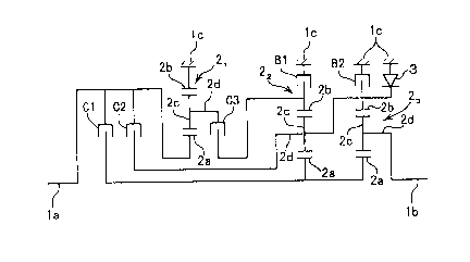
Referring to Fig. 1, reference numeral 1 denotes an
automatic transmission for a vehicle, and the automatic
transmission lcomprises a planetary-gear type transmission for
six forward ranges and a single reverse range in which first
to third three planetary gears 21, 22, 23 are disposed between
an input shaft la for connecting a fluid torque converter to
an engine (not shown) and an output shaft lb connected to a
driving wheel of the vehicle via a differential gear (not
shown).
The planetary gears 21, 22, 23each comprises a sun gear
2a, a ring gear 2b, pinions 2c that are brought into mesh
engagement with the sun and ring gears 2a, 2b and a carrier 2d
for rotatably supporting the pinions. The sun gear 2a of the
first planetary gear 2lis coupled to the input shaft la, the
carrier 2d of the third planetary gear 23 is coupled to the output
shaft lb. In addition, the ring gear 2b of the first planetary
gear 21 is coupled to a casing lc of the transmission 1 for
preventing the rotation thereof. The sun gears 2a, 2a of the
second and third planetary gears 2z, 2j are coupled to each other,
and the carrier 2d of the second planetary gear 22 and the ring
gear 2b of the third planetary gear 2j are coupled to each other,
this ring gear 2b being coupled to the casing lc via a one-
way clutch 3 as a reaction force receiver.
Provided in the transmission 1 as hydraulic coupling
elements are a first clutch C1 for coupling the input shaft la
to the sun gears 2a, 2a of the second and third planetary gears
22, 23 , a second clutch C2 for coupling the input shaft la to
6
CA 02299804 2000-03-O1
the carrier 2d of the second planetary gear 22, a third clutch
C3 for coupling the carrier 2d of the first planetary gear 21
to the ring gear 2b of the second planetary gear 2z, a first
brake B1 for coupling the ring gear 2b of the second planetary
gear 22 to the casing lc and a second brake B2 for coupling the
ring gear 2b of the third planetary gear 23 to the casing lc.
According to the above construction, when the first
clutch C1 and the second brake B2 are brought into engagement
at the same time, a first speed gear is established. When the
first clutch C1 and the first brake B1 are brought into
engagement at the same time, a second speed range is established.
When the first clutch C1 and the third clutch C3 are brought
into engagement at the same time, a third speed range is
established. When first clutch C1 and the second clutch C2 are
brought into engagement at the same time, a fourth speed range
is established. When the second clutch C2 and the third clutch
C3 are brought into engagement at the same time, a fifth speed
range is established. Further, when the second clutch C2 and
the first brake Bl are brought into engagement at the same time,
a sixth speed gear is established, and when the third clutch
C3 is brought into engagement with the second brake B2 , a reverse
range is established.
These clutches C1, C2 , C3 and brakes B1, B2 operate and
are controlled through a hydraulic circuit shown in Fig. 2.
Provided in this hydraulic circuit are a hydraulic pressure
source 4, a manual valve 5, first to fifth five shift control
valves 61 to 65, and first to fifth five solenoid valves 71 to
75. The first to fifth five shift control valves 61 to 65
7
CA 02299804 2000-03-O1
individually control the supply and drain of the oil to and from
the clutches C1, C2, C3 and the brakes B1, B2. The first to
fifth five solenoid valves 71 to 75 individually control the
five shift control valves 61 to 65.
The manual valve 5 is constructed so as to be switched
over in interlocking with operations of a shift selector lever
(not shown) to five shift positions; a "P" position as a parking
range, an "R" position as a reverse range, an "N" as a neutral
range (a position shown in the figure), a "D" position as an
automatic speed change range for forward travel, and an "M"
position as a manual speed change range for forward travel. At
the "D" and "M" positions, an oil passage L1 communicating with
the oil pressure source 4 is connected to an oil passage L2,
whereby a pressure oil regulated to a predetermined line
pressure with a regulator 8 is supplied to the oil passage L2,
and the pressure oil is then supplied to the second shift control
valve 6z for the second clutch C2 via the oil passage L2 at all
times. In addition to this, the pressure oil is also supplied
to the first shift control valve 61 for the first clutch C1,
the fourth shift control valve 64 for the first brake B1 and
the fifth shift control valve 65 for the second brake B2, via
an oil passage L3 connected to the oil passage L2 via a fail-safe
valve 9 that will be described later. The shift control valve
63 for the third clutch C3 is supplied with the pressure oil
via the oil passage L1 at all times independently from the manual
valve 5.
Moreover, oil passages L4, L5, L6 and L7 communicating
respectively with the first to third clutches C1, C2, C3 and
8
CA 02299804 2000-03-O1
the first brake B1 are directly connected respectively to the
first to fourth shift control valves, 61, 62, 63, 64. But, oil
passage L8 communicating with the second brake B2 is constructed
so as to selectively be connected to the fifth shift control
valve 65 and oil passage L9 communicating with the manual valve
5 via a shuttle valve 10. The oil passage L9 is connected to
the oil passage L1 when the manual valve 5 is in the "R" position,
and therefore, with the manual valve in that "R" position, the
second brake B2 is engaged at all times, and when the third clutch
C3 is supplied with the pressure oil from the third shift control
valve 63 and is then brought into engagement, the reverse range
is established.
The respective shift control valves 61, 6z, 63, 64, 65
comprise an oil chamber 6a for pushing the respective shift
control valves 61, 62, 63, 64, 65 to a leftward oil supply position,
an oil chamber 6b for pushing them to a rightward oil drain
position (a position shown in the figure) and a spring 6c
accommodated in the oil chamber 6b. Signal pressures from the
respective solenoid valves 71 to 75 are inputted into the
corresponding oil chambers 6a of the respective shift control
valves 61 to 55 via respective oil passages L10 to L14
communicating, respectively, with the respective solenoid
valves 71 to 75. Further, hydraulic pressures on the downstream
side of the respective shift control valves 61 to 65 are inputted
into the oil chambers 6b of the respective shift control valves
61 to 65, and hydraulic pressures on the downstream side of the
respective shift control valves 61 to 65, that is, the hydraulic
pressures of the respective hydraulic coupling elements C1, C2,
9
CA 02299804 2000-03-O1
C3, B1, B2 are regulated in response to signal pressures from
the respective solenoid valves 71 to 75.
The respective solenoid valves 71 to 75 comprises solenoid
proportional valves adapted to output a signal pressure in
accordance with a current value at which solenoids 7a of the
solenoid valves 71 to 75 are excited. Then, the excitation of
the solenoids 7a of the solenoid valves 71 to 75 are controlled
by an electric control circuit 11 composed of a mounted computer.
A modulator pressure (a certain pressure lower than the line
pressure) from a modulator valve 12 connected to the oil passage
L1 is inputted into the respective solenoid valves 71 to 75,
and a signal pressure outputted in a fully opened state becomes
a modulator pressure.
When the manual valve 5 is in the "D" and "M" pos itions ,
all the shift control valves 61 to 65 can be supplied with the
pressure oil. When the signal pressures from the first and fifth
solenoid valves 71, 75 are increased, the pressure oil is
supplied to the first clutch C1 and the second brake B2 via the
first and fifth shift control valves 61, 65, whereby the first
speed range is established. When the signal pressures from the
first and fourth solenoid valves 71, 7q are increased, the
pressure oil is supplied to the first clutch C1 and the first
brake B1 via the first and fourth shift control valve 61, 64,
whereby the second speed range is established. When the signal
pressures from the first and third solenoid valves 71, 73are
increased, the pressure oil is supplied to the first and third
clutches C1, C3 via the first and third shift control valves
61, 6j, whereby the third speed range is established. When the
CA 02299804 2000-03-O1
signal pressures of the first and second solenoid valves 71,
72 are increased, the pressure oil is supplied to the first and
second clutches C1, C2 via the first and second shift control
valves 61, 6z, whereby the fourth speed range is established.
When the signal pressures from the second and third solenoid
valves 7z, 7, are increased, the pressure oil is supplied to
the second and third clutches C2 , C3 via the second and third
shift control valves 62, 63, whereby the fifth speed range is
established. Further, when the signal pressures from the
second and fourth solenoid valves 72, 74 are increased, the
pressure oil is supplied to the second clutch C2 and the first
brake B1 via the second and fourth shift control valves 6z, 64,
whereby the sixth speed range is established.
Then, the manual valve 5 is in the "D" position, the
respective solenoid valves 71 to 75 are controlled by an
electronic control circuit 11 in response to the running
condition of the vehicle, whereby automatic shifts are carried
out between the first speed and sixth speed. Further, when the
manual valve 5 is in the "M" position, the respective solenoid
valves 71 to 75 are controlled by the electronic control circuit
11 by operating upshift and downshift switches ( not shown ) and
an upshift or downshift is performed every time the upshift
switch or downshift switch is switched on. In addition, in
shifting speed gears, an increase in pressure of the hydraulic
coupling elements that are brought into engagement at the same
time in shifting and a decrease in pressure of the hydraulic
coupling elements that are released from the engaged states in
shifting is suitably controlled with the solenoid valves
11
CA 02299804 2000-03-O1
adapted to operate so as to produce no shift shock.
Here, the first, fourth and fifth solenoid valves 71, 74.
75 are constituted by normally-closed type solenoid valves,
while the second and third solenoid valves 7z, 73 by
normally-opened solenoid valves. The relationship between
exciting conditions of the solenoids 7a of the respective
solenoid valves 71 to 75 and engagement conditions of the
hydraulic coupling elements C1 to C3, B2, B3 when the respective
speed ranges are established at the "D" and "M" positions is
illustrated as shown in Fig. 3. In the figure, the sign 0
indicates that the hydraulic coupling elements are coupled, the
sign X indicates that they are released.
As is clear from Fig. 3, in this mode for carrying out
the invention, the first clutch C1 and the second clutch C2
constitutes the hydraulic coupling elements of the first group,
and the third clutch C3, the first brake B1 and the second brake
B2 constitute the hydraulic coupling elements of the second
group. And, the first to sixth speed ranges are selectively
established through a simultaneous engagement of the first and
second clutches C1, C2 that are the hydraulic coupling elements
of the first group and an simultaneous engagement of either of
the first and second clutches C1, C2 and any of the third clutch
C3, the first brake B1 and the second brake B2 that are the
hydraulic coupling element of the second group.
Even if there occurs a case in which three or more
hydraulic coupling elements are engaged at the same time, or
two hydraulic coupling elements of the second group are engaged
at the same time, specifically, when the third clutch C3 and
12
CA 02299804 2000-03-O1
the first brake B1 which belong to the second group are brought
into engagement at the same time, there is caused a double
meshing, whereby the transmission 1 is put into a locked state.
Further, if the third clutch C3 and the second brake B2 which
belong to the second group are brought into engagement at the
same time during the forward travel, the reverse range is
established, and this results in putting an excessive load on
the transmission 1 or the engine.
To this end, in the mode for carrying out the invention,
the common oil passage L3 is connected to the oil supply ports
of the first, fourth and fifth shift valves 61, 64, 65 other than
the shift control valves 62, 63 corresponding to the second and
third clutches C2, C3 which are being intended to establish a
predetermined single speed range, for instance, the fifth speed
range, and the fail-safe valve 9 is interposed between this oil
passage L3 and the oil passage L2 which is an oil supply passage.
Thus, the supply of pressure oil to the first, fourth and fifth
shift control valves 61, 64, 65 can be stopped at the time of
a failure in which the pressure oil is simultaneously supplied
to a plurality of hydraulic coupling elements that must not
simultaneously be brought into engagement, whereby the
aforesaid problem can be prevented.
The fail-safe valve 9 can freely be switched to a leftward
open position where the oil passage L2 and oil passage L3 are
connected to each other and a rightward closed position (the
position shown in the figure) where the connection so
established is disconnected. A line pressure from the oil
passage L1 is inputted into an oil chamber 9a at the right end
13
CA 02299804 2000-03-O1
so as to push the fail-safe valve 9 to an open position side.
In addition, four oil chambers 9b, 9c, 9d, 9e are formed in the
fail-safe valve 9 for pushing it toward a closed position side.
The hydraulic pressure of the third clutch C3 is inputted into
the oil chamber 9b from an oil passage L6a branching off from
the oil passage L6. The hydraulic pressure of the first brake
B1 is inputted into the oil chamber 9c from an oil passage L7a
branching off from the oil passage line L7. The hydraulic
pressure of the second brake B2 is inputted into the oil chamber
9d from the oil passage L8a branching off from a connecting oil
passage between the fifth shift control valve 65 and the shuttle
valve 10. In addition, a signal pressure outputted from a
resultant signal pressure valve 13, which will be described
later, is inputted into the oil chamber 9e, and furthermore,
the fail-safe 9 is biased with a spring 9f to the closed position
side. Then, when the hydraulic pressures that are inputted into
any two oil chambers of the oil chambers 9b, 9c, 9d, 9e becomes
equal to or larger than a predetermined value, a resultant force
of a pushing force by these hydraulic pressures and the biasing
force of the spring 9f exceeds a pushing force by the line
pressure inputted into the oil chamber 9a, whereby the
fail-safe valve 9 is constructed so as to be switched over to
the closed position.
The resultant signal valve 13 can freely be switched over
between the rightward open position where the oil passage L2
is connected to the oil chamber 9e (the position shown in the
figure) and the leftward closed position where the connection
so established is disconnected. In addition, a line pressure
14
CA 02299804 2000-03-O1
from the oil passage L1 is inputted into a right end oil chamber
13a of the resultant signal valve 13, to thereby push the valve
13 to an open position side, and two oil chambers 13b, 13c are
provided in the resultant signal valve 13 for pushing it to a
closed position side. The hydraulic pressure of the second
clutch C2 is inputted into the oil chamber 13b via an oil passage
L5a branching off from the oil passage L5 and the hydraulic
pressure of the first clutch C1 is inputted into the oil chamber
13c via an oil passage L4a branching off from the oil passage
L4, and further, the resultant signal valve 13 is biased toward
the closed position side with a spring 13d. Thus, when there
is produced a state in which the first and second clutches C1,
C2 are both brought into engagement (fourth speed range), a
resultant force of the pushing force by the hydraulic pressures
inputted into the oil chambers 13b, 13c and the biasing force
of the spring 13d exceeds the pushing force resulting from the
line pressure inputted into the oil chamber 13a, whereby the
resultant signal valve 13 is constructed so as to be switched
over to the open position.
Thus, when the first and second clutches C1, C2 which are
the hydraulic coupling elements of the first group are both
brought into engagement, the line pressure from the oil passage
L1 which is the output signal pressure of the resultant signal
valve 13 is inputted into the oil chamber 9e of the fail-safe
vale 9. In this state, if the pressure oil is supplied to any
of the third clutch C3, the first brake B1 and the second brake
B2 which are hydraulic coupling elements of the second group,
the fail-safe valve 9 is switched over to the closed position.
CA 02299804 2000-03-O1
In addition, even in a state in which only one of both the first
and second clutches C1, C2 is brought into engagement, or the
clutches C1, C2 are both released and no line pressure is
inputted into the oil chamber 9e, when the pressure oil is
supplied to two or more of the third clutch C3, the first brake
B1 and the second brake B2, the fail-safe valve 9 is switched
over to the closed position. Then, when the fail-safe valve 9
is switched over to the closed position, the connection between
the oil passage L2 and the oil passage L3 is disconnected. Thus,
at the time of failure, the supply of pressure oil to the first,
fourth and fifth shift control valves 61, 64, 65 is stopped, and
the hydraulic coupling elements C1, B1, B2 corresponding to
those shift control valves are released.
On the other hand, the following construction can be
considered. That is, the resultant signal valve 13 is omitted,
and five oil chambers are provided in the fail-safe valve 9 for
pushing it to the closed position side. The hydraulic pressures
of the first clutch C1, the second clutch C2, the third clutch
C3, the first brake B1 and the second brake B2 are inputted into
the five oil chambers. When the hydraulic pressures inputted
into three or more oil chambers of those five oil chambers
increase, in other words, three or more hydraulic coupling
elements are brought into engagement at the same time, the
fail-safe valve 9 is constructed so as to be switched over to
the closed position. With this construction, however, the valve
length of the fail-safe valve 9 becomes long, and there is
increased the possibility that a valve stick is caused. In
addition, lands are formed on the fail-safe valve on the side
16
CA 02299804 2000-03-O1
facing the oil chambers, and due to this, the diameter of the
valve element becomes thicker sequentially as it extends toward
the end on the closed position side, and as with the aforesaid
case, when the five oil chambers are provided, the diameter of
the valve element at the end thereof becomes quite thick, this
increasing the mass of the valve element, whereby the response
of the valve element when the fail-safe valve 9 is switched over
from the open position to the closed position is deteriorated.
To cope with this, with the present embodiment, there are needed
only four oil chambers 9b, 9c, 9d, 9e that are provided in the
fail-safe valve 9 for pushing it to the closed position side,
and therefore, not only can the valve length of the fail-safe
valve 9 be made shorter but also the diameter of the fail-safe
valve 9 can be made thin, whereby the weight of the fail-safe
valve 9 can be reduced, thereby making it possible to improve
the toughness against the valve stick and response at the time
of valve position switching of the fail-safe valve 9.
Furthermore, in this mode for carrying out the invention,
an oil passage L15 is provided which is connected to the oil
passage 2 via the fail-safe valve 9 when the fail-safe valve
9 is located at the closed position. Further, the oil passage
L6a and the oil passage L15 are connected to the oil chamber
9b of the fail-safe valve 9 via a shuttle valve 141, and the
oil passage L7a and the oil passage L15 are connected to the
oil chamber 9c of the fail-safe valve 9 via a shuttle valve 14z.
Thus, once the fail-safe valve 9 is switched over to the closed
position at the time of failure, the line pressure from the oil
passage L2 is inputted into the oil chambers 9b, 9c via the oil
17
CA 02299804 2000-03-O1
passage L15. And, even if the hydraulic pressures of the
hydraulic coupling elements C1, B1, B2 are reduced when the
supply of pressure oil to the first, fourth and fifth shift
control valves 61, 64, 65 is stopped, the fail-safe valve 9 can
be held at the closed position, the chattering of the fail-
safe valve 9 being thus prevented.
Even if the fail-safe valve 9 is switched over to the
closed position at the time of failure, since the oil passage
L2 and oil passage L1 which both function as an oil supply passage
are connected to the second shift control valve 6~ and the third
shift control valve 63, respectively, the fifth speed range can
be established by allowing the second clutch C2 and the third
clutch C3 to be brought into engagement. However, when the
second solenoid valve 72 and third solenoid valve 73 fail and
cannot be controlled, whereby the second shift control valve
62 and the third shift control valve 63 cannot be switched over
to the oil supply position side, in other words, when high signal
pressures cannot be outputted from the solenoid valves 7z, 73
due to the on-failure thereof (a failure in which the solenoids
are kept excited ) , the pressure oil cannot be supplied to the
second and third clutches C2, C3, and thus, the fifth speed range
cannot be established.
To cope with this, in this embodiment, second oil chambers
6d are formed in the second and third shift control valves 62,
6" respectively, for pushing them to the oil supply position
side. The oil passage L15 is then connected to the second oil
chambers 6d, and when the fail-safe valve 9 is situated at the
closed position, the line pressure from the oil passage L2 which
18
CA 02299804 2000-03-O1
is the oil supply line is inputted into the oil chambers 6d via
the oil passage L15, whereby the respective shift control valves
62, 63 are constructed so as to be switched to and held at the
oil supply position in a forcible fashion. Thus, when the
fail-safe valve 9 is switched over to the closed position at
the time of failure, the pressure oil is forcibly supplied to
the second and third shift control valves 62, 63, whereby the
fifth speed range can be established. On the other hand, it may
be constructed such that the oil passage into which the signal
pressures of the solenoid valves are inputted and the oil
passage Z15 are connected to the oil chambers 6a of the second
and third shift control valves 6z, 63 via the shuttle valves,
whereby the line pressure from the oil passage L2 at the failure
time is inputted into the oil chamber 6a via the oil passage
L15 and the shuttle valves, so that the respective shift control
valves 62, 63 can be switched to and held at the oil supply
position.
In addition, the excitation of all the solenoid valves
71 to 75 is stopped when the system goes down due to disconnection
or the like, only the signal pressures of the second and third
solenoid valves 7z, 73 which are of the normally-opened type
increase, the pressure oil is supplied to the second and third
clutches C2, C3 via the second and third shift control valves
62, 63, whereby the fifth speed range is established. However,
only with the fifth speed range available, the start and
low-speed running becomes difficult. Consequently, it is
desired that, when the system is down, the fifth speed range
is established with the "D" position, while with the "M"
19
' CA 02299804 2000-03-O1
position, a speed range lower than the fifth speed range, for
example, the third speed range is established, that is, the
fifth speed range and third speed range can be attained by
switching operation between the "D" and "M" ranges . To this end,
instead of the second clutch C2, the first clutch C1 needs to
be engaged at the "M" position.
Then, in this embodiment for carrying out the invention,
a switching valve 15 is provided for selectively switching the
oil passage L11 communicating with the second solenoid valve
7z between the oil chamber 6a of the second shift control valve
6z and the oil chamber 6a of the first shift control 61.
Accordingly, when the system goes down, at the "D" position,
the oil passage L11 is connected to the second shift control
valve 62, and the second shift control valve 6z is switched to
the oil supply position with a high signal pressure from the
second solenoid valve 72 to thereby allow the second clutch C2
to be engaged, while at the "M" position, the oil passage 11
is connected to the oil chamber 6a of the first shift control
valve 61, whereby the first shift control valve 61 is switched
to the oil supply position to thereby allow the first clutch
C1 to be engaged.
The switching valve 15 is adapted to freely be switched
to a first switching position (a position shown in the figure)
where the oil passage L10 communicating with the first solenoid
valve 71 and the oil passage L11 communicating with the second
solenoid valve 7z are connected, respectively, to the oil
chamber 6a of the first shift control valve 61 and the oil chamber
6a of the second shift control valve 62, and a second switching
CA 02299804 2000-03-O1
position where those connections are disconnected to thereby
connect the oil passage L11 to the oil chamber 6a of the first
shift control valve 61, and the switching valve 15 is biased
with a spring 15a to the first switching position. In addition,
provided in the switching valve 15 are an oil chamber 15b at
a left end for pushing the switching valve 15 to the first
switching position side and an oil chamber 15c at a right end
for pushing the same valve to the second switching position side.
Then, an oil passage L16, which is connected to the oil passage
L1 when the manual valve 5 is in the "D" position and is made
to open to the atmosphere when the valve 5 is in the "M" position,
is connected to the oil chamber 15b, and the signal pressure
from the second solenoid valve 7z is inputted into the oil
chamber 15c via an oil passage 17 branching off from the oil
passage L11. Thus, at the "D" position, the line pressure from
the oil passage L1 is inputted into the oil chamber 15b, and
even when the signal pressure from the second solenoid valve
72 becomes a highest pressure (modulator pressure) due to the
system going down, the switching valve 15 is held at the first
switching position. But, at the "M" position, since the oil
chamber 15b is made to open to the atmosphere via the oil passage
L16, when the signal pressure from the second solenoid valve
72 becomes a highest pressure due to the system going down, the
switching valve 15 is switched to the second position, and as
described above, the first shift control valve 61 is switched
over to the oil supply position to thereby allow the first clutch
Cl to be engaged, the third speed range being thereby
established.
21
CA 02299804 2000-03-O1
When the system goes down while the vehicle is running
at high speeds with a speed range faster than the fourth speed
range in the "M" position, resulting in a downshift to the third
speed range, there is a probability of excessive revolutions
of the engine. To cope with this, in this embodiment for carrying
out the invention, a closing valve 16 is disposed along the oil
passage L17 which is able to be switched between a rightward
open position where the oil passage L17 is opened (a position
shown in the figure) and a leftward closed position where the
oil passage L17 is closed. Then, the closing valve 16 is pushed
to an open position side with a spring 16a, and an oil passage
Z7 communicating with the first brake B1 that is engaged when
a speed range lower than the third speed range, such as the second
speed range is established is connected to an oil chamber 16b
at a right end of the closing valve 16, whereby the closing valve
16 is constructed so as to be switched to the closed position
against the spring 16a by virtue of the hydraulic pressure of
the first brake B1 when the second speed range is established.
In addition, formed in the closing valve 16 is an annular groove
16c communicating with the oil passage L2 when it is located
at the closed position, and the diameter of a land on the
left-hand side of this annular groove 16c is made larger than
that of a land on the right-hand side thereof, whereby once the
closing valve 16 is switched to the closed position, a leftward
pushing force resulting from the difference in land diameter
between the left and right lands is applied thereto, thus the
closing valve 16 being held at the closed position irrespective
of the hydraulic pressure of the first brake B1.
22
CA 02299804 2000-03-O1
According to the above construction, the closing valve
16 is switched to the closed position when the second speed range
is established after the vehicle starts with the "D" or "M"
position engaged, and thereafter, as long as the "D" or "M"
position is kept engaged, the closing valve 16 is held at the
closed position, whereby the signal pressure from the second
solenoid valve 7z is not inputted into the oil chamber 15c of
the switching valve 15. Thus, even if the system goes down at
the "M" position, the switching valve 15 is not switched to the
second switching position, and at the time of system down, the
fifth speed range can be established, whereby there is no risk
of downshift to the third speed gear even when the system goes
down while the vehicle is running at high speeds . In addition,
even if the closing valve 16 is switched to and held at the closed
position, when the shift selector lever is put into the "N"
position, since the oil passage L2 is made to open to the
atmosphere, the closing valve 16 is restored to the open
position by virtue of the biasing force of the spring 16a. Thus,
when the system goes down, if the shift selector lever is put
in the "M" position after being once put in the "N" position,
the switching valve 15 is switched to the second switching
position, and thus the third speed range is established as
described above, and moreover, by range switching operations
between the "D" and "M" positions, the vehicle can be shifted
to the fifth and third speed ranges.
Furthermore, in this mode for carrying out the invention,
the respective shift control valves 61 to 65 are constructed
so as to be controlled by the electronic control circuit 11 via
23
CA 02299804 2000-03-O1
the respective solenoid valves 71 to 75, but the respective shift
control valves 61 to 65 may be constituted by solenoid valves,
whereby the respective shift control valves 61 to 65 may be
constructed so as to directly be controlled by the electronic
control circuit 11.
While only certain embodiments of the invention have been
specifically described herein, it will apparent that numerous
modifications may be made thereto without departing from the
spirit and scope of the invention.
As is clear from the description made heretofore,
according to the present invention, not only can the valve
length of the fail-safe valve be made shorter but also the
diameter of the valve element can be made thinner to thereby
reduce the weight thereof, there by making it possible to
improve the toughness against the valve stick and response in
switching of the fail-safe valve.
24