Language selection

Search

Patent 2299836 Summary

Third-party information liability

Some of the information on this Web page has been provided by external sources. The Government of Canada is not responsible for the accuracy, reliability or currency of the information supplied by external sources. Users wishing to rely upon this information should consult directly with the source of the information. Content provided by external sources is not subject to official languages, privacy and accessibility requirements.

Claims and Abstract availability

Any discrepancies in the text and image of the Claims and Abstract are due to differing posting times. Text of the Claims and Abstract are posted:

  • At the time the application is open to public inspection;
  • At the time of issue of the patent (grant).
(12) Patent Application: (11) CA 2299836
(54) English Title: APPARATUS AND METHOD FOR DRIVING A HYDRAULIC SYSTEM OF A CONSTRUCTION MACHINE, IN PARTICULAR A HYDRAULIC EXCAVATOR
(54) French Title: APPAREIL ET METHODE D'ENTRAINEMENT D'UN SYSTEME HYDRAULIQUE DE MACHINE DE CONSTRUCTION, EN PARTICULIER UNE PELLE HYDRAULIQUE
Status: Deemed Abandoned and Beyond the Period of Reinstatement - Pending Response to Notice of Disregarded Communication
Bibliographic Data
(51) International Patent Classification (IPC):
  • F15B 13/06 (2006.01)
  • E02F 09/20 (2006.01)
  • E02F 09/22 (2006.01)
  • F15B 13/04 (2006.01)
  • F15B 21/10 (2006.01)
(72) Inventors :
  • MEYER, JOACHIM (Germany)
  • EHRICH, GERD (Germany)
(73) Owners :
  • KOMATSU MINING GERMANY GMBH
(71) Applicants :
  • KOMATSU MINING GERMANY GMBH (Germany)
(74) Agent: SMART & BIGGAR LP
(74) Associate agent:
(45) Issued:
(22) Filed Date: 2000-03-02
(41) Open to Public Inspection: 2000-09-04
Examination requested: 2000-06-02
Availability of licence: N/A
Dedicated to the Public: N/A
(25) Language of filing: English

Patent Cooperation Treaty (PCT): No

(30) Application Priority Data:
Application No. Country/Territory Date
199 11 440.4 (Germany) 1999-03-04

Abstracts

English Abstract


An apparatus and method for driving a hydraulic
system of a construction machine, in particular a hydraulic
excavator that has a plurality of control blocks (1a to 1d)
which are fed via each at least one pump (2a to 2d) and each of
which drives a plurality of hydraulically operated actuators of
the construction machine. At least two control blocks (1c, 1d)
are connected to drive a common actuator. The delivery
capacity of the pump (2d) of the second (1d) of these control
blocks can be connected up to the actuator via a delay element
(3).


Claims

Note: Claims are shown in the official language in which they were submitted.

CLAIMS:
1. An apparatus for driving a hydraulic system of a
construction machine, such as a hydraulic excavator, said
hydraulic system having a plurality of control blocks (1a to
1d) which are fed each via at least one pump (2a to 2d) and
each of which drives a plurality if hydraulically operated
actuators of the construction machine, at least two of said
control blocks (1c, 1d) being designed to drive an actuator in
common, wherein the delivery capacity of the pump (2d) of a
second of said at least two control blocks can be connected up
to said common actuator via a delay element (3).
2. The apparatus as claimed in claim 1, wherein the
delay element (3) is constructed in the manner of a time relay
(4) which connects up the pump (2d) of said second control
block (1d) after the expiry of a permanently predefinable time
period.
3. The apparatus as claimed in claim 1, wherein the
delay element (3) comprises a sensor element (9) which
registers the speed of said common actuator and whose output
data is processed by an electronic unit (8) which connects up
the pump (2d) of said second control block (1d) when the final
speed of the actuator is reached.
4. The apparatus as claimed in claim 1, wherein the
delay element (3) comprises a sensor element (10) which
determines the pressure in the hydraulic circuit of said common
actuator and whose output data is processed by an electronic
unit (8') which connects up the pump (2d) of said second
control block (1d) in response to a pressure drop which occurs
after the acceleration phase of the common actuator.
7

5. The apparatus as claimed in any one of claims 1 to 4
wherein the actuator is a hydraulic slewing mechanism motor.
6. The apparatus as claimed is any one of claims 1 to 5
wherein said hydraulic system is that of a hydraulic excavator
and comprises at least four control blocks (1a to 1d) each
having a pump (2a to 2d) of which: a first control block (1a)
drives the working equipment and the right-hand side of the
running gear; a second control block (1b) drives the working
equipment and the left-hand side of the running gear; a third
control block (1c) drives the working equipment and the slewing
mechanism; and a fourth control block (1d) drives the working
equipment and the stewing mechanism; one of the pumps (2c, 2d)
assigned to the third and fourth control blocks (1c, 1d) being
available to the stewing mechanism via the delay element (3).
7. A method of driving the hydraulic system of a
construction machine, in which a plurality of control blocks
are fed each via a pump and in which a plurality of
hydraulically operated actuators are driven each via control
block, at least one actuator being driven via two control
blocks, wherein the delivery capacity of the pump of a second
of said two control blocks is connected up to the actuator with
a delay.
8. The method as claimed in claim 7, wherein the pump of
said second control block is connected up after the expiry of a
permanently predefined time period.
9. The method as claimed in claim 7, wherein the pump of
said second control block is connected up to the actuator with
a delay in such a way that the speed of the actuator is
measured and the pump of the second control block is connected
up to the actuator only when the final speed of the actuator is
reached.
8

10. The method as claimed is claim 7, wherein the pump of
said second control block is connected up to the actuator with
a delay in such a way that the pressure in the hydraulic
circuit of the actuator is measured and the pump of the second
control block is connected up only when the pressure drops
after the acceleration phase has been carried out.
9

Description

Note: Descriptions are shown in the official language in which they were submitted.


CA 02299836 2000-03-02
' 20337-533
Apparatus and Method f'or Driving a Hydraulic System of a
Construction Machine, in Particular a Hydraulic Excavator
Description
The invention relates to an apparatus and a method
for driving a hydraulic system of a construction machine, in
particular, but not exclusively a hydraulic excavator.
As is generally known, the hydraulic system of a
powerful hydraulic excavator has a plurality of control blocks,
each fed via a pump. Each control block is used to drive a
plurality of hydraulic actuators. Thus, for example, a first
control block can drive the working equipment as well as the
right-hand running gear, a second control block can drive the
working equipment as well as the left-hand running gear, a
third control block can drive the working equipment as well as
the stewing mechanism, and a fourth control block can drive the
working equipment as well as, likewise, the stewing mechanism.
This division of the pump output between the control blocks
ensures the effective supply of the various hydraulic actuators
with pressure medium.
Since it is usual for the stewing mechanism to be
switched on only for about 25% of a working cycle, here the
pump of the stewing mechanism circuit can also be used for the
working equipment circuit. When the movement of the stewing
mechanism is initiated, however, the quantity delivered by the
pump is concentrated onto the stewing mechanism circuit. As a
result of this, it is no longer available to the working
equipment circuit, in particular the boom cylinder. On the
other hand, a major part of the available quantity delivered by
the pump is only needed at the end of the acceleration phase of
the stewing unit, since at the beginning of the acceleration
phase it is a high torque (pump pressure) at a low speed (pump
1

CA 02299836 2000-03-02
20337-533
delivery quantity) which is preferentially needed. Only when
the angular speed of the slewing mechanism superstructure rises
does the requirement on the quantity delivered by the pump rise
accordingly, the ultimate consequence of which is that as the
angular speed of the superstructure rises, a slowing down of
the movement of the working equipment, in particular the boom,
occurs.
It is therefore the object of the present invention
to reduce the impairment to the performance of a hydraulic
system of the type mentioned above.
The invention provides an apparatus for driving a
hydraulic system of a construction machine, such as a hydraulic
excavator, said hydraulic system having a plurality of control
blocks (la to ld) which are fed each via at least one pump (2a
to 2d) and each of which drives a plurality of hydraulically
operated actuators of the construction machine, at least two of
said control blocks (lc, ld) being designed to drive an
actuator in common, wherein the delivery capacity of the pump
(2d) of a second of said at least two control blocks can be
connected up to said common actuator via a delay element (3).
The invention further provides a method of driving
the hydraulic system of a construction machine, in which a
plurality of control blocks are fed each via a pump and in
which a plurality of hydraulically operated actuators are
driven each via control block, at least one actuator being
driven via two control blocks, wherein the delivery capacity of
the pump of a second of said two control blocks is connected up
to the actuator with a delay.
In a hydraulic system in which at least two control
blocks are designed to drive a common actuator, the invention
includes the technical teaching of connecting_up the delivery
2

CA 02299836 2000-03-02
20337-533
capacity of the pump of~the second control block to the
actuator via a delay element.
It is preferred if this drive is used for the
hydraulic slewing mechanism motor as actuator. In contrast to
S the switching on of both pumps simultaneously for the slewing
movement of the superstructure, initially only one pump is used
to accelerate the superstructure from the rest position. Since
the flow requirement for pressure medium rises with increasing
angular speed, the second pump is connected up only when the
first pump reaches its delivery limit. Up to this point, the
second pump is still completely available to the other
actuators which can be driven by the control block assigned to
it. Overall, switching on with a delay reduces the impairment
to the performance of a hydraulic system of the type under
consideration.
Switching on the second pump with a delay can be
implemented in accordance with three preferred alternatives.
Firstly, the delay element can be constructed in the manner of
a time relay which connects up the pump of the second control
block after the expiry of a permanently predefinable time
period. In this case, the predefinable time period has to be
determined and optimized by trials. Secondly, the delay
element can contain a sensor element which registers the speed
of the actuator and whose output data is processed by an
electronic unit which connects up the pump of the second
control block when the final speed of the actuator is reached.
As the third alternative, it is possible for the delay element
to comprise a sensor element which determines the pressure in
the hydraulic circuit of the actuator and whose output data is
processed by an electronic unit which connects up the pump of
the second control block in response to the pressure drop which
occurs after completion of the acceleration phase of the
3

CA 02299836 2000-03-02
20337-533
actuator. In the case of the last two alternative embodiments
mentioned, attainment of the final speed or occurrence of the
pressure drop are the events on the basis of which the demand
for additional pump capacity is indicated. As a result of the
second pump being connected up, the actuator experiences an
additional acceleration thrust which is suitable at the time of
the demand, so that the slewing mechanism, as a whole can be
positioned rapidly and, at the same time, minimum impairment
occurs in the supply to other actuators to be driven via the
same control block.
Further measures which improve the invention are
illustrated in more detail below together with the description
of a preferred embodiment of the invention and with reference
to the figures, in which:
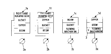
Fig. 1 shows a connection diagram of a hydraulic
system of a hydraulic excavator;
Fig. 2a shows a detailed representation of a delay
element with time-controlled connection;
Fig. 2b shows a detailed representation of a delay
element with final-speed-controlled connection; and
Fig. 2c shows a detailed representation of a delay
element with pressure-drop-controlled connection.
The hydraulic system of a hydraulic excavator
comprises a total of four control blocks la to ld. Each
control block la to ld is supplied with pressure medium by
means of an associated hydraulic pump 2a to 2d. The first
control block la controls the right-hand side of the running
gear and the bucket, dipper and boom components of the working
equipment (not shown). The second control block lb controls
the left-hand side of the running gear and, likewise, the
4

CA 02299836 2000-03-02
20337-533
bucket, dipper and boom components of the working equipment
(not shown). The third control block lc controls the slewing
mechanism and the boom and bucket components of the working
equipment (not shown). The fourth control block ld is
responsible for driving the dipper and boom of the working
equipment and, likewise, for driving the slewing mechanism (not
shown). The fourth control block ld is additionally assigned a
delay element 3 which is assigned to the slewing mechanism
circuit. Via the delay element 3 it is possible to make the
delivery capacity of the pump 2d associated with the control
block ld available to the slewing mechanism circuit. As a
result of this, the delivery capacity of the pump 2c of the
third control block lc is fully exhausted first for moving the
slewing mechanism before the second pump 2d is additionally
used for this purpose.
The delay element 3 can contain a time relay 4
according to figure 2a. The time relay 4 has a setting element
5 with which the delay time period can be set manually. If,
then, the switch-on signal for the slewing mechanism comes into
the delay element 3 via the input 6, this signal is connected
through to the output 7 by the time relay 4 only after the
expiry of the time period defined via the setting element 5.
According to Figure 2b, the delay element 3 can also
be constructed from an electronic unit 8, whose input is
connected to a speed sensor 9. The speed sensor 9 registers
the current angular speed of the slewing mechanism. The
switch-on signal for the slewing mechanism, which is fed to the
input 6' is switched through to the output 7' only when the
electronic unit 8 registers a value lying within the range of
the final speed of the slewing mechanism during the
acceleration phase.
5

CA 02299836 2000-03-02
'. 20337-533
According to Figure 2c, the delay element 3, as an
alternative to the two previous embodiments, contains an
electronic unit 8', which accepts the signals of a pressure
sensor 10 on the input side. The pressure sensor 10 registers
the current pressure in the slewing mechanism circuit. At the
end of the acceleration phase effected by the pump 2c, a
pressure drop occurs in the slewing mechanism circuit. This
event is registered by the electronic unit 8', in order to
switch through to the output 7" the switch-on signal from the
slewing mechanism which is present on the inlet 6" and, to this
extent, to connect up the pump 2d to the slewing mechanism with
a delay.
The implementation of the invention is not restricted
to the preferred exemplary embodiments indicated above.
Instead, a number of variants are conceivable which make use of
the solution illustrated, even in the case of designs of
fundamentally different type.
6

Representative Drawing
A single figure which represents the drawing illustrating the invention.
Administrative Status

2024-08-01:As part of the Next Generation Patents (NGP) transition, the Canadian Patents Database (CPD) now contains a more detailed Event History, which replicates the Event Log of our new back-office solution.

Please note that "Inactive:" events refers to events no longer in use in our new back-office solution.

For a clearer understanding of the status of the application/patent presented on this page, the site Disclaimer , as well as the definitions for Patent , Event History , Maintenance Fee  and Payment History  should be consulted.

Event History

Description Date
Inactive: IPC from MCD 2006-03-12
Application Not Reinstated by Deadline 2005-09-26
Inactive: Dead - Final fee not paid 2005-09-26
Deemed Abandoned - Failure to Respond to Maintenance Fee Notice 2005-03-02
Deemed Abandoned - Conditions for Grant Determined Not Compliant 2004-09-27
Notice of Allowance is Issued 2004-03-25
Letter Sent 2004-03-25
Notice of Allowance is Issued 2004-03-25
Inactive: Approved for allowance (AFA) 2004-03-16
Amendment Received - Voluntary Amendment 2003-11-21
Inactive: S.30(2) Rules - Examiner requisition 2003-05-21
Application Published (Open to Public Inspection) 2000-09-04
Inactive: Cover page published 2000-09-03
Letter Sent 2000-06-28
Request for Examination Received 2000-06-02
Request for Examination Requirements Determined Compliant 2000-06-02
All Requirements for Examination Determined Compliant 2000-06-02
Inactive: IPC assigned 2000-05-01
Inactive: First IPC assigned 2000-05-01
Inactive: Filing certificate - No RFE (English) 2000-03-23
Letter Sent 2000-03-23
Application Received - Regular National 2000-03-22

Abandonment History

Abandonment Date Reason Reinstatement Date
2005-03-02
2004-09-27

Maintenance Fee

The last payment was received on 2004-02-11

Note : If the full payment has not been received on or before the date indicated, a further fee may be required which may be one of the following

  • the reinstatement fee;
  • the late payment fee; or
  • additional fee to reverse deemed expiry.

Patent fees are adjusted on the 1st of January every year. The amounts above are the current amounts if received by December 31 of the current year.
Please refer to the CIPO Patent Fees web page to see all current fee amounts.

Fee History

Fee Type Anniversary Year Due Date Paid Date
Registration of a document 2000-03-02
Application fee - standard 2000-03-02
Request for examination - standard 2000-06-02
MF (application, 2nd anniv.) - standard 02 2002-03-04 2001-12-05
MF (application, 3rd anniv.) - standard 03 2003-03-03 2002-11-26
MF (application, 4th anniv.) - standard 04 2004-03-02 2004-02-11
Owners on Record

Note: Records showing the ownership history in alphabetical order.

Current Owners on Record
KOMATSU MINING GERMANY GMBH
Past Owners on Record
GERD EHRICH
JOACHIM MEYER
Past Owners that do not appear in the "Owners on Record" listing will appear in other documentation within the application.
Documents

To view selected files, please enter reCAPTCHA code :


To view images, click a link in the Document Description column. To download the documents, select one or more checkboxes in the first column and then click the "Download Selected in PDF format (Zip Archive)" or the "Download Selected as Single PDF" button.

List of published and non-published patent-specific documents on the CPD .

If you have any difficulty accessing content, you can call the Client Service Centre at 1-866-997-1936 or send them an e-mail at CIPO Client Service Centre.


Document
Description 
Date
(yyyy-mm-dd) 
Number of pages   Size of Image (KB) 
Representative drawing 2000-08-29 1 7
Claims 2003-11-20 3 96
Description 2000-03-01 6 274
Claims 2000-03-01 3 106
Abstract 2000-03-01 1 18
Drawings 2000-03-01 2 24
Courtesy - Certificate of registration (related document(s)) 2000-03-22 1 113
Filing Certificate (English) 2000-03-22 1 163
Acknowledgement of Request for Examination 2000-06-27 1 177
Reminder of maintenance fee due 2001-11-04 1 112
Commissioner's Notice - Application Found Allowable 2004-03-24 1 161
Courtesy - Abandonment Letter (NOA) 2004-12-05 1 167
Courtesy - Abandonment Letter (Maintenance Fee) 2005-04-26 1 174
Fees 2002-11-25 1 42