Note: Descriptions are shown in the official language in which they were submitted.
CA 02299862 2000-03-02
Circuit arrangement and method for operating at least
one high-pressure discharge lamp
The invention relates to a circuit arrangement for
operating at least one high-pressure discharge lamp
according to the preamble of patent claim 1, and to an
operating method for a high-pressure discharge lamp.
I. Prior art
A circuit arrangement of this type is disclosed for
example in the international patent application with
the publication number WO 98/18297. This laid-open
specification describes a circuit arrangement for the
high-frequency operation of a high-pressure discharge
lamp, that is to say for operating the high-pressure
discharge lamp on an alternating voltage at a frequency
above 200 kHz and preferably even above 500 kHz. The
circuit arrangement has a voltage converter which
generates a high-frequency alternating voltage at its
output. The output of this voltage converter is formed
by the two secondary windings of a transformer. The
first secondary winding is connected into a load
circuit which is designed as a series resonant circuit
and is provided with the lamp terminals, while the
second secondary winding is connected to the voltage
input of a starter. The starter is a pulse starter,
which applies unipolar high-voltage pulses to the high-
pressure discharge lamp during the starting phase by
means of an auxiliary starting electrode. In the case
of lamp operation with high alternating voltage
frequencies of this type, it is difficult to generate
the necessary starting voltage for the high-pressure
discharge lamp with the aid of a Tesla transformer,
since the secondary windings of the transformer must
have only a low inductance at such high frequencies -
CA 02299862 2000-03-02
_ 2 -
because of their otherwise excessively high internal
impedance and the inadequately low transfer of power
which results from this.
II. Summary of the invention
The object of the invention is to provide a circuit
arrangement for operating at least one high-pressure
discharge lamp with a high-frequency alternating
voltage, which has an improved starter for starting a
gas discharge in the at least one high-pressure
discharge lamp, and to specify an improved operating
and starting method for a high-pressure discharge lamp
fed with a high-frequency alternatirig voltage.
According to the invention, this object is achieved by
the characterizing features of patent claim 1.
Particularly advantageous embodimerLts of the invention
are described in the subclaims.
The circuit arrangement according to the invention has
a voltage converter for generating a high-frequency
alternating voltage at its alternating voltage output,
a load circuit which is connected to the alternating
voltage output and which has at least one lamp
inductor, a coupling capacitor and terminals for at
least one high-pressure discharge lamp, and a starter
for starting a gas discharge in the at least one high-
pressure discharge lamp, the starter being provided
with a high-voltage source and a high-voltage DC
output. The coupling capacitor is connected to the
high-voltage DC output via a charging resistor. As a
result of this measure, during the starting phase the
coupling capacitor is charged with the high DC voltage
generated by the starter and, during the starting
phase, serves as a voltage source for the load circuit
and in particular for the at least one high-pressure
discharge lamp. After the gas discharge has been
started in the at least one high-pressure discharge
CA 02299862 2000-03-02
_ 3 _
lamp, the coupling capacitor is discharged via the
electrically conductive discharge path in the at least
one high-pressure discharge lamp. The discharge current
flowing via the at least one high-pressure discharge
lamp from the coupling capacitor contributes
significantly to the production and stabilization of
the discharge arc in the at least one high-pressure
discharge lamp. In particular, the discharge current
flowing through the at least one high-pressure
discharge lamp from the coupling capacitor shortens the
transition time from the undesired glow discharge,
which damages the lamp electrodes, to the arc
discharge.
The high-voltage source of the starter is
advantageously designed as a cascade circuit for
voltage multiplication of the output voltage of the
voltage converter, or as a secondary winding coupled
inductively to the lamp inductor, possibly with a
downstream cascade circuit for voltage multiplication.
In order to prevent the voltage converter being
destroyed by excessively high starting voltages, a
voltage-limiting component is advantageously connected
in parallel with the alternating voltage output of the
voltage converter. The voltage-limiting components used
are advantageously bidirectional diodes, for example
Transil diodes, or varistors, because they can be
loaded with high electrical outputs.
The load circuit of the voltage converter
advantageously also has a resonance capacitor which,
with the lamp inductor, forms a series resonant
circuit. As a result, the method of resonance
enhancement can also be used for providing the
discharge arc transfer energy and for generating the
operating voltage for the at least one high-pressure
discharge lamp. In the particularly preferred exemplary
embodiments, the resonance capacitor is connected in
parallel with the series circuit comprising the
CA 02299862 2000-03-02
- 4 -
coupling capacitor and the at least one high-pressure
discharge lamp. As a result, the starting voltage for
the at least one high-pressure discharge lamp is formed
from the additive superimposition. of the high DC
voltage present across the coupling capacitor and the
resonance-enhanced high-frequency alternating voltage
from the voltage converter, which is present across the
resonance capacitor.
The voltage converter is advantageously designed as a
single-ended converter or as a push--pull converter, for
example as a push-pull inverter. These voltage
converters are particularly suitable for converting a
comparatively low DC voltage of, for example, 12 V or
24 V, which is usual in motor vehicles, into a high-
frequency alternating voltage having an amplitude of
about 500 V and a frequency of more than 500 kHz.
III. Description of the preferred exemplary embodiments
The invention will be explained in more detail below
with reference to a preferred exemplary embodiment. In
the drawings:
Figure 1 shows a schematic illustration of the first
exemplary embodiment of the circuit
arrangement according to the invention
Figure 2 shows a schematic illustration of the second
exemplary embodiment of the circuit
arrangement according to the invention with a
load circuit designed as a series resonant
circuit
Figure 3 shows the circuit arrangement according to
Figure 1 or 2 with a starter which has a
secondary winding above the lamp inductor, in
a schematic illustration
CA 02299862 2000-03-02
_ 5 -
Figure 4 shows the circuit arrangement according to
Figure 1 or 2 with a starter which has a
cascade circuit for voltage multiplication,
in a schematic illustratiori
Figure 5 shows the circuit arrangement according to
Figure 2 with a voltage converter designed as
a single-ended converter operating
resonantly, in a schematic illustration.
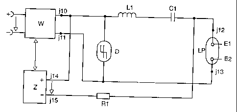
Figure 1 shows a block diagram of the circuit
arrangement according to the invention. It has a
voltage converter W, which is fed by a voltage source,
and, at its alternating voltage output j10, jil,
provides a high-frequency alternating voltage for the
high-frequency operation of a high-pressure discharge
lamp LP. Connected to the alternating voltage output
j 10, jll of the voltage converter W is a load circuit,
which has a lamp inductor L1, a coupling capacitor Cl,
two terminals j12, j13 for a high-pressure discharge
lamp LP and a bidirectional diode circuit D, which
comprises, for example, two series-connected oppositely
poled Zener diodes or a Transil diode D. When a high-
pressure discharge lamp is connected, the two terminals
j12, j13 are each connected to a lamp electrode El and
E2, respectively. The lamp inductor L1, the coupling
capacitor Cl and the discharge path between the lamp
electrodes El, E2 are then connected in series. The
Transil diode D is arranged in parallel with the
alternating voltage output j10, jll.
The circuit arrangement depicted in Figure 1 also has a
starter Z, which has a high-voltage source and a high-
voltage DC output j14, j15. The high-voltage DC output
j14, j15 is connected via a charging resistor R1 to the
series circuit L1, Cl comprising the lamp inductor L1
and the coupling capacitor C1. For this purpose,
according to Figure 1, the positive terminal j14 of the
high-voltage DC output is connected to the terminal jlO
CA 02299862 2000-03-02
- 6 -
of the alternating voltage output from the voltage
converter W, to the lamp inductor Ll and to the Transil
diode D. The negative terminal j15 of the high-voltage
DC output is connected via the charging resistor R1 to
the coupling capacitor C1 and to the lamp terminal j12.
The second lamp terminal j13 is connected to the
terminal jll of the alternating voltage output and to
the Transil diode. The coupling capacitor has a
capacitance of 1.1 nF, and the inductance of the lamp
inductor is 45 H.
From the low DC voltage of, for example, 12 V or 24 V
or else 42 V present on its voltage input, the voltage
converter W generates a high-frequency alternating
voltage with an amplitude of about 500 V and a
frequency above 500kHz, and provides this at its
alternating voltage output j10, j11 in order to operate
the high-pressure discharge lamp LP. However, this
alternating voltage is not sufficient to start the gas
discharge in the high-pressure discharge lamp LP. The
load circuit connected to the alternating voltage
output j10, j11 of the voltage converter W is therefore
initially interrupted between the two lamp electrodes
El, E2. The starter Z generates, on its high-voltage DC
output j14, j 15, a DC voltage of up to 25 kV, which is
sufficient to start the gas discharge in the high-
pressure discharge lamp LP. The coupling capacitor Cl
is charged, via the charging resistor R1 and via the
lamp inductor Ll, to the high DC voltage generated by
the starter Z. During the starting phase, it serves as
a high-voltage source for the load circuit and, in
particular, for the high-pressure discharge lamp LP.
After the gas discharge in the high-pressure discharge
lamp LP has been started, the discharge path between
the two lamp electrodes El, E2 becomes electrically
conductive. The coupling capacitor Cl is then
discharged via the now conductive discharge path of the
.high-pressure discharge lamp LP and, by this means,
contributes to the formation and the stabilization of a
CA 02299862 2000-03-02
- 7 -
discharge arc between the lamp electrodes El, E2 and to
shortening the warm-up phase of the high-pressure
discharge lamp LP. In addition, after the gas discharge
has been started, the load circuit is no longer
interrupted, so that the high-frequency alternating
voltage generated by the voltage converter W then
permits a high-frequency alternating current to flow
via the discharge path El-E2 of the high-pressure
discharge lamp LP. The Transil diode D serves as an
overvoltage protection for the voltage converter W. If
the voltage drop across the coupling capacitor Cl
exceeds a critical threshold value, determined by the
Transil diode D, the Transil diode E) becomes conductive
and the coupling ::apacitor Cl is primarily discharged
via the Transil diode D instead of via the discharge
path El-E2 of the high-pressure discharge lamp LP.
Figure 2 shows a block diagram of the circuit
arrangement according to the inve:ntion with a load
circuit designed as a series resonant circuit. This
circuit arrangement differs from the circuit
arrangement depicted in Figure 1 only by an additional
resonance capacitor C2 which, with the lamp inductor
L1, forms a series resonant circuit and which is
connected in parallel with the series circuit
comprising the coupling capacitor C1 and the high-
pressure discharge lamp LP. The capacitance of the
resonance capacitor C2 is 80 pF. Because of the
additional resonance capacitor C2, the operating method
of the high-pressure discharge lamp LP on the circuit
arrangement according to Figure 2 differs slightly from
the operating method of the high-pressure discharge
lamp LP on the circuit arrangement according to
Figure 1. As soon as the voltage converter W provides a
high-frequency alternating voltage at its alternating
voltage output j10, jll, a high-frequency alternating
current flows through the load circuit designed as a
series resonant circuit, that is to say via the lamp
inductor L1 and the resonance capacitor C2. In order to
CA 02299862 2000-03-02
_ 8 -
start the gas discharge in the high-pressure discharge
lamp LP, the starter Z generates a high DC voltage at
its DC output j14, j15 and charges the coupling
capacitor Cl, via the charging resistor R1, to a high
DC voltage of up to 25 kV. During the starting phase,
both the coupling capacitor Cl and the resonance
capacitor C2 of the high-pressure discharge lamp LP
serve as a voltage source. During the starting phase,
the high DC voltage of the coupling capacitor Cl and
the high-frequency alternating voltage of the resonance
capacitor C2 are superimposed additively on the high-
pressure discharge lamp LP. During the starting phase
and during the warm-up phase of the high-pressure
discharge lamp LP, the voltage converter W is
preferably operated in such a way that it generates a
high-frequency alternating voltage whose frequency is
close to the resonant frequency of the series resonant
circuit. As a result, a resonance-enhanced high-
frequency alternating voltage is generated across the
resonance capacity C2, which both improves the
formation and stabilization of a discharge arc in the
high-pressure discharge lamp LP and shortens the warm-
up phase of the high-pressure discharge lamp LP - that
is the operating phase directly after the gas discharge
has been started, during which the ionizable filling
components contributing to the light emission of the
high-pressure discharge lamp evaporate. After the gas
discharge has been started in the high-pressure
discharge lamp LP, the coupling capacitor Cl is
discharged via the then conductive discharge path E1-E2
of the lamp. At the end of the warm-up phase of the
high-pressure discharge lamp LP, that is to say when
all the filling components of the lamp LP have achieved
their equilibrium partial pressure, the voltage
converter W is controlled in such a way that it
generates, on its alternating voltage output j10, jll,
a high-frequency alternating voltage whose frequency
has a sufficient distance from the resonant frequency
of the series resonant circuit, so that resonance
CA 02299862 2000-03-02
- 9 -
enhancement no longer occurs on the lamp inductor L1
and on the resonance capacitor C2. Here, too, the
Transil diode D serves to protect the voltage converter
W from voltage overload by the voltages present on the
coupling capacitor Cl or on the resonance capacitor C2
during the starting phase.
Figures 3 and 4 depict two different embodiments of the
starter Z, which can be used for both of the exemplary
embodiments shown in Figures 1 anci 2 of the circuit
arrangement according to the invention, that is to say
for a load circuit without and with a resonance
capacitor C2. For this reason, the resonance capacitor
C2 is in each case illustrated by dashed lines in
Figures 3 and 4. The starter Z according to Figure 3
comprises a secondary winding L2 coupled inductively to
the lamp inductor L1, a rectifier diode Dl connected in
series with the secondary winding L2 and a capacitor C3
arranged in parallel with,the series circuit comprising
secondary winding L2 and rectifier diode Dl. The
secondary winding L2 serves as a high-voltage source
for the starter Z. When the voltage converter W is
switched on, a high voltage is induced in the secondary
winding L2 and is rectified by the diode Dl. This
rectified high voltage is fed to the coupling capacitor
Cl via the resistor R1, as already explained above.
In Figure 4, the starter Z is designed as a cascade
circuit for voltage multiplication of the alternating
voltage provided by the voltage converter W at its
alternating voltage output j10, jll. The cascade
circuit has, for example, twenty stages, of which only
the first and the last are shown iri Figure 4, in order
to convert the 500 V alternating voltage from the
voltage converter W into a 20kV DC voltage. The voltage
input of the cascade circuit is connected to the
alternating voltage output j10, jll of the voltage
converter W. The high-voltage output from the cascade
circuit is connected via the charging resistor R1 to
CA 02299862 2000-03-02
- 10 -
the coupling capacitor C1 and to the lamp terminal j12.
The construction and functioning of a cascade circuit
for voltage multiplication are described, for example,
on page 220 of the book "Bauelemente der Elektronik und
ihre Grundschaltungen" [Electronic components and their
basic circuits] by H. Hoger, F. Kahler and G. Weigt,
published by H. Stam GmbH (7th edition).
In Figure 5, the voltage converter W of the second
exemplary embodiment (Figure 2) is designed as a
single-ended converter operating resonantly. The
single-ended converter W has a field effect transistor
T1, a transformer TR with a primary winding nl and a
secondary winding n2, and a drive device (not depicted)
for the field effect transistor T1, as well as a
capacitor C4. The primary winding nl and the drain-
source junction of the field effect: transistor T1 are
connected in series. The secondary winding n2 of the
transformer TR is connected to the terminals j10, j11
of the alternating voltage output of the single-ended
converter W. It serves as a high-frequency alternating
voltage source for the load circuit. The gate electrode
of the field effect transistor T1 :is connected to the
drive device. The capacitor C4 is arranged in parallel
with the drain-source junction of the field effect
transistor Ti. The switching cycle of the field effect
transistor T1 determines the frequency of the induced
voltage generated in the secondary winding. During the
starting phase and during the warm-up phase of the
high-pressure discharge lamp LP, the field effect
transistor Tl is driven, by means of the drive device,
in such a way that the frequency of the induced voltage
generated on the secondary windirlg n2 lies in the
vicinity of the resonant frequeiicy of the series
resonant circuit C2, L1. As a result, during the
abovementioned operating phases, a resonantly enhanced
high-frequency alternating voltage occurs on the
resonant-circuit components L1 and C2. The resonant
frequency of the series resonant circuit L1, C2 is
CA 02299862 2000-03-02
- 11 -
approximately 2.653 MHz, on the basis of the
abovementioned dimensioning of these components. After
the starting phase and the warm-up phase have been
completed, the high-pressure discharge lamp LP is
operated with a high-frequency alternating voltage of
approximately 1 MHz. In order to avoid the occurrence
of acoustic resonances in the discharge plasma, this
operating frequency is modulated with a frequency of
100 kHz, so that the frequency of the lamp voltage is
0.9 MHz to 1.1 MHz. After the warm-up phase has been
completed, the operating voltage of: the high-pressure
discharge lamp LP is about 80 V.
The high-pressure discharge lamp LP is a metal halide
high-pressure discharge lamp with an electrical power
consumption of approximately 35 watts, which is
operated in a motor vehicle headlamp using the on-board
voltage of the motor vehicle. In Figures 1 to 5,
identical components have been provided with the same
reference symbols. Table 1 specifies suitable
dimensions for the circuit components.
The invention is not restricted to the exemplary
embodiments explained in more detail above. For
example, instead of a single-ended converter (Figure
5), a push-pull converter, for example a push-pull
inverter, can also be used, its alternating voltage
output being formed by the secoridary winding of a
transformer.