Note: Descriptions are shown in the official language in which they were submitted.
CA 02300388 2000-02-07
1
DEVICE AND METHOD FOR REPLACING AN INTERCHANGEABLE PART OF
AN INGOT ARRANGEMENT IN A CONTINUOUS CASTING INSTALLATION
The invention relates to a continuous casting installation
having a device for exchanging a replaceable part of a mould
arrangement in the continuous casting installation according
to the precharacterising clause of claim 1 and to a method of
exchanging a replaceable part of the continuous casting
installation according to claim 1.
lOAs a rule, in continuous casting installations, especially
continuous steel casting installations, it is necessary from
time to time to replace a mould or at least a component of a
mould. Thus, for example; when the cavity of a mould is
subjected constantly to the effects of strand solidification,
the wall defining the mould cavity eventually begins to
exhibit wear phenomena and has to be repaired or replaced.
Accidents occurring during casting operation, such as
perforation of a strand shell or overflow of the metal melt
over the pouring opening of the mould, lead, as a rule, to an
20interruption in casting operation of the relevant mould. In
general, parts of the continuous casting installation, in
particular the mould or parts of the mould and strand guiding
devices below the mould have to be freed from solidified
metal or even replaced before casting operation may be
resumed.
Moulds are conventionally supported in a continuous casting
installation by a holding device which is so constructed that
the moulds may oscillate in a casting position. The holding
device usually takes the form of an oscillating table, which
is accessible from above for the purpose of installing and
30removing a mould. In a multi-strand installation with moulds
having vertical or oblique cavities, tundishes are arranged
AMENDED SHEET
CA 02300388 2000-02-07
2
above the moulds during casting operation, molten metal being
poured from these tundishes into the mould cavities, wherein
a plurality of moulds is conventionally supplied with melt
from one tundish comprising several outlets. An accident
entailing replacement of a mould requires the casting
operation to be stopped at the mould affected by the accident
and consequently results in a reduction in the casting yield
of the multi-strand installation, since the tundish blocks
access to the moulds from above and the necessary mould
exchange is only possible in a break in casting after removal
of the tundish.
A continuous casting installation is known from US-PS 3 273
208 which is suitable for long sequential casts and is
provided with an apparatus for quick mould replacement. The
mould is arranged on a sliding table which is capable of
rectilinear, horizontal displacement and interacts with a
mould delivery carriage displaceable perpendicularly thereto
or with a turntable. The displaceable sliding table requires
20 open holes in the teeming platform floor along the
displacement path, which holes are undesirable for reasons of
safety. If a turntable is used in conjunction with multi-
strand installations, large gaps are needed between strands,
making large tundishes necessary. Installation of this
swapping device in multi-strand installations leads not only
to high structural complexity but also to high operating
costs, stemming from maintenance of the wear-prone tundishes.
Moreover, when molten metal is poured from one tundish into a
plurality of. moulds, variations occur in the casting
30 parameters, for example differences in casting temperature or
in the superheating temperature in the various moulds. These
variations are generally greater, the larger the strand
spacing and lead to unacceptable variations in the quality of
the strands withdrawn from the different moulds.
JOS 62-9749, which provides the precharacterising clause of
claim 1, discloses a device for exchanging a mould in a
continuous casting installation equipped with an oscillatory
AMENDED SHEET
CA 02300388 2000-02-07
3
holding device for the mpuld. The holding device comprises a
deck, to which the mould may be fixed in an operating
position and the height of which may be adjusted by means of
two lever systems provided with independent drives. A first
lever system enables the deck to be lowered and raised and
serves as a conveying device for conveying the mould out of
the operating position into a second position, in which the
mould may be gripped by a second conveying device below the
teeming platform, lifted from the deck and conveyed on
further. A second lever system permits oscillation of the
mould about the position set by the first lever system, the
assembly comprising the mould, the deck and .the first lever
system being set in motion as a whole by means of the second
lever system. This design'has the disadvantage that, during
casting operation, a relatively large overall weight has to
be kept in motion in order for the mould to oscillate and
that the first lever system has to undergo complex
stabilisation with respect to the vibrations transmitted by
the second lever system, in order to be able to maintain the
casting conditions in a controlled manner over a relatively
long period. Furthermore, in the initial phase of mould
replacement a relatively large weight in addition to the
mould has to be moved by means of the conveying device.
A mould is known from DE 32 07 149, which is attached in
releasable manner to an oscillating elevating platform and
comprises a water chamber, upper and lower flange plates, a
water conveying jacket and a mould tube. The flange plates,
the mould tube and the water conveying jacket form a unit,
held together by connecting members, which may, as a compact,
adjusted structural component, be withdrawn upwards out of
the water chamber by a crane or introduced from above into
the water chamber and can therefore only be exchanged above
the mould during a break in casting and after removal of the
tundish.
AMENDED SHEET
CA 02300388 2000-02-07
3a
LU 84 507 discloses a multistrand casting installation with
an arrangement of moulds in which each mould, including all
its accessories, such as in particular the mould oscillating
device, is arranged on a frame which is mounted on a
lowerable platform so as to be displaceable in the
longitudinal direction. When the platform has been lowered,
the mould may be moved, together with the oscillating device,
which consists of an oscillating mechanism and a drive motor,
along the platform to a position below the operating
position, where it may be separated from the oscillating
device and then exchanged. With this arrangement too, a
relatively large weight has to be moved before the mould may
be exchanged.
The object of the invention is to avoid the disadvantages of
the known devices and to provide a structurally simplified
device and a method for exchanging a replaceable part of a
mould arrangement in a continuous casting installation, the
intention being to make it possible to carry out the
replacement process on an individual selected mould in a
multi-strand installation while the casting operation remains
active.
AMENDED SHEET
CA 02300388 2000-02-07
4
This object is achieved in accordance with the invention by a
continuous casting installation according to claim 1 and a
method according to claim 14.
It is assumed that, in addition to a mould cavity wall, which
forms a strand, the mould comprises a supporting structure
for the mould cavity wall. By means of the supporting
structure, a separable connection may be produced between the
mould cavity wall and the oscillatory holding device. The
holding device determines the casting position of the mould.
A part of the mould arrangement which is connected with the
replaceable part during the casting operation, which defines
the spatial arrangement of the replaceable part, designated
below as the operating position of the replaceable part, and
which remains behind when the replaceable part is removed
from the operating position with the aid of the conveying
device is designated the stationary part. By definition, the
stationary part comprises at least the holding device.
According to the invention, the replaceable part comprises at
least one component of the mould, wherein the holding device
and the replaceable part are so constructed that the
replaceable part may be moved by means of the conveying
device out of the operating position into a space below the
casting position after separation from the stationary part.
By first of all separating the replaceable part from the
stationary part at the beginning of the replacement process,
the replaceable part is uncoupled from the oscillatory
holding device. In this way, it is possible to replace the
replaceable part without moving the stationary part. Thus,
the weight load on the conveying device when in operation may
be reduced to a minimum. Moreover, the conveying device may
be so designed that it is separate from the holding device
and the holding device, together with the mould, may
oscillate during the casting operation without being affected
by the conveying device.
AMENDED SHEET
CA 02300388 2000-02-07
4a
Since, according to the invention, the replaceable part may
be moved out of the operating position into a space below the
casting position by means of the conveying device after
separation from the stationary part, the replaceable part may
AMENDED SHEET
CA 02300388 2000-02-07
be exchanged in multi-strand installations even during the
casting operation, even if tundishes above the moulds block
access to the replaceable parts from above. Moreover, it is
possible for multi-strand installations to be produced with
5 any strand spacing desired and for a device according to the
invention to be constructed to conform to a predetermined
strand spacing. Strand spacing may be minimised if, for
example, the conveying device is designed in such a way that
a mould may be moved in the strand guiding direction into the
space below the casting position. In this way, movement of
the mould towards an adjacent strand is prevented.
Different embodiments of the device according to the
invention are distinguished by the configuration of the mould
arrangement. This may be such that parts of the mould and/or
the mould.i-tself may be replaced. In each instance, the
replaceable part may be gripped by the conveying device.
In one embodiment, the replaceable part merely comprises the
mould cavity wall. Thus, it is possible to replace only that
part of a mould which is subject to the greatest wear,
without having to move the other parts of the mould or the
mould arrangement, which are as a rule of a much greater
weight than the mould cavity wall. The stationary part of the
mould arrangement may be equipped with guide members, to
simplify automatic positioning of the replaceable part upon
movement into its operating position. Seals, which may be
incorporated into the guide members, are provided to seal the
mould cavity wall automatically during exchange against the
leakage of coolant, which may act on the mould cavity wall.
This embodiment is particularly easy to produce in
conjunction with a spray-cooled mould; in this instance, a
spray cooling device for cooling the mould cavity wall may be
associated with the stationary part of the mould arrangement.
This embodiment may also be used, however, in moulds having
water jacket cooling.
CA 02300388 2000-02-07
6
In another embodiment, the replaceable part consists of the
mould cavity wall with a coolant channel for cooling the
mould cavity wall. The coolant channel may take the form, for
example, of a water cooling jacket surrounding the mould
cavity wall. In the case of such an embodiment, it is
particularly advantageous to provide the stationary part of
the mould arrangement with a supply connection for the
coolant, such that the coolant channel is automatically
connected to the supply connection when the replaceable part
is brought into the. operating position.
In a further embodiment of the invention, the replaceable
part comprises the mould in its entirety. In this case, the
supporting structure of the mould cavity wall is connected
separably with the holding device in~such a way that the
mould may be gripped by the conveying device and moved out of
the operating position into a space below the casting
position.
The mould or mould arrangement may conventionally comprise
devices which serve to influence the casting and/or
solidification processes and/or the monitoring~and/or control
of the operation of the continuous casting installation.
Further embodiments according to the invention differ as to
which of the above-mentioned devices are associated with the
stationary part of the mould arrangement and which with the
replaceable part.
It is advantageous to arrange on the replaceable part devices
which are intended to act on an exiting strand directly at
the outlet opening of the mould cavity. Examples of these
devices are foot rollers and/or spray cooling devices and/or
an electromagnetic agitator for the strand.
Devices which have to be replaced less frequently may
advantageously be constructed as components of the stationary
part of the mould arrangement and connected with the holding
CA 02300388 2000-02-07
7
device, for example at the periphery of the mould, or, if the
supporting structure for the mould cavity wall is associated
with the stationary part, be arranged on the supporting
structure. Examples of such devices are devices for
electromagnetic agitation and/or braking of the metal melt in
the mould cavity and/or in the strand or a spray cooling
device for the strand. If such devices are particularly .
heavy, then their association with the stationary part of the
mould arrangement results in a particularly advantageous
embodiment of the device according to the invention, since
the conveying device may be designed to cope with smaller
loads. '
Similarly, devices which have to be operated in conjunction
with complex supply apparatuses may advantageously be
associated with the stationary part of the mould arrangement,
so that the gate to the supply apparatus need not be of an
excessively complex design, for example in the form of
detachable supply connections. Into this category fall, for
example, measuring devices for monitoring the casting
operation, especially for measuring the level of the meniscus
and/or for monitoring the temperature of parts of the mould.
Further embodiments of the device according to the invention
relate to a replaceable part comprising one or more
components requiring supply via stationary supply.
connections. In this instance, the stationary part comprises
at least one supply connection and the replaceable part is so
constructed that the supply connection is coupled to or
uncoupled from a corresponding supply connection during
exchange of the replaceable part in order respectively to
effect or undo a supply connection. Such supply connections
may serve in the supply of energy or coolants or lubricants
or in the exchange of signals. For example, by means of
automatically connectable supply connections an electro-
magnetic agitator incorporated into the replaceable part may
be supplied with electrical energy, a lubricant duet opening
CA 02300388 2000-02-07
8
into the mould cavity may be fed with lubricant or measuring
and/or control signals may be exchanged between a
controllable device connected with the replaceable part.or a
measuring probe, for example a temperature probe for
measuring the temperature in the mould cavity wall or other
segments of the replaceable part, and control and/or
measuring devices at the periphery of the replaceable part.
Various embodiments are feasible for the conveying device,
depending on the configuration of the mould arrangement. The
conveying device may comprise a lifting device, with which'
the replaceable part may be connected and which is
constructed 'in such a way that the replaceable part may be .
moved out of the operating position into,the space below the
casting position. The conveying device may be constructed in
such a way that the replaceable part may be moved out of the
operating position substantially tangentially, at least along
a proportion of its path, to the strand conveying direction
at the outlet opening. This embodiment of the conveying
device has the advantage that the replaceable part traverses
a particularly small space during exchange. In this way it is
possible to make the mould arrangement particularly compact.
If, in particular, components of the stationary part of the
mould arrangement, for example an electromagnetic agitator or
2~5 a meniscus measuring device, are positioned at as small as
possible a distance from the replaceable part, there is
little play available when the replaceable part is removed
from its operating position during exchange.
In another modification of the conveying device, the
replaceable part may be moved out of the operating position
on a path which is in part rectilinear and/or in part curved.
This results in the advantageously useful possibility of
moving the replaceable part out of the operating position
into any appropriate position in which the replaceable part
may undergo further treatment. In a continuous casting
installation in which the strand is guided through a
CA 02300388 2000-02-07
9
secondary cooling chamber immediately after leaving the
mould, it is possible, for example, for the conveying device
to be constructed in such a way that it may be positioned
outside the secondary cooling chamber and the replaceable
part may be gripped by means of a closable opening in the
cooling chamber wall and, after moving tangentially to the
strand guiding direction, be conveyed sideways out of the
secondary cooling chamber. During the casting operation, the
conveying device would be extensively protected from
influences which might impair said casting operation, for
example developing from strand breakaway, by the cooling
chamber wall. Moreover, it is possible to construct the
conveying device as a mobile unit. In the case of multi-
strand installations, this construction has the advantage
that several moulds may be served by the same conveying
device, by positioning the conveying device, as~appropriate,
in the vicinity of the replaceable part to be exchanged. It
is also feasible to arrange the conveying device stationarily
with respect to the continuos casting installation. For
example, each mould may be associated with a conveying
device. This avoids complex positioning of a conveying device
once it has been adapted to one replaceable part. In this
way, automation of a device according to the invention is
simplified.
Examples~of the invention will be described below with the
aid of Figures, in which:
Fig. 1 shows a vertical section through a mould
arrangement
Fig. 2 shows a vertical section through a two-strand
installation
Fig. 3 shows a vertical section through a further
example of a mould arrangement,
Fig. 4 shows a vertical section through a further
example of a mould arrangement,
Fig. 5 shows a section along line IV-IV of Fig. 4,
CA 02300388 2000-02-07
Fig. 6 shows a vertical section through a further
example of a mould arrangement, and
Fig. 7 ~ shows a section along line VI-VI of Fig. 6.
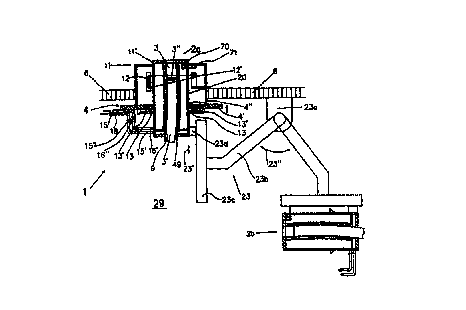
5 Fig. 1 shows a mould arrangement 1 which projects through an
opening in the floor 6 of a teeming platform. The mould
arrangement 1 comprises a mould 2 with a mould cavity 3 and a
holding device 4 for the mould 2. The mould 2 is designed to
be a replaceable part of the mould arrangement 2 and may be
10 separated from the other components of the mould arrangement
1 forming a stationary part and moved by means of a conveying
device 23. Reference numerals 2a, 2b etc. will be used below
to indicate different positions of the mould 2. The mould
cavity 3 consists of a mould cavity wall 9 with a pouring
15. opening at the upper end and an outlet opening for a strand
3' at the lower end of the mould 2. Fig. 1 shows the strand
3' as a solidified strand remnant which is cut off directly
at the outlet opening of the mould 2 and comprises an upper
end 3" corresponding to the meniscus during casting
operation. The mould 2 comprises an external jacket 20 which
serves as a supporting structure for the mould cavity wall 9
and may be connected to the holding device 4. The space
between the jacket 20 and the mould cavity wall 9 is
constructed for the passage of a coolant, for example water,
wherein a gap between the mould cavity wall 9 and a pipe 49
surrounding the mould cavity wall 9 serves as a coolant
.channel through which the coolant may be conveyed from a
supply line 15' to a discharge line 16'.
The holding device 4 is constructed as a mould table 4' with
an opening through which the mould 2 may be brought from
below into a casting position 2a and with wedges 13'
displaceable along the mould table 4'. As is indicated in
Fig. 1 by a double-headed arrow in the strand guiding
direction, the holding device 4 may be caused to oscillate by
a drive which is not shown. The casting position 2a is
defined by positioning members 13 which are connected with
CA 02300388 2000-02-07
11
the mould 2 and which may be brought into releasable
connection with the mould table 4' by means of the wedges
13'. The ends of the coolant supply and discharge lines 15'
and 16' remote from the jacket 20 of the mould are each
constructed as supply connections. These are so formed that
they may be separably connected at coupling points 15" and
16" with corresponding coolant supply and discharge lines 15
and 16 arranged on the stationary part of the mould
arrangement when the mould is brought into the casting
position 2a.
During casting operation, the part of the mould 2a projecting
beyond the mould table 4' is surrounded by a casing 11, which
houses various devices required during casting operation and
associated with the stationary part of the mould arrangement
1, for example a measuring unit, consisting of, a radioactive
radiator 12 and a detector 12', for monitoring the meniscus
3" or an electromagnetic agitator (not shown). An example of
an energy and/or signal supply connection which may be
effected~or separated during exchange of the mould 2a is the
temperature measuring device 70 indicated in Fig. 1, which is
installed to measure the temperature of the coolant at the
end of the pipe 49 on the outlet side and may be connected
via electrical contacts on the outside of the mould with
corresponding contacts 71 on the casing 11, in order to
ensure the supply of electrical energy or the exchange of
measuring and/or control signals.
The conveying device 23 enables the mould 2 to move with two
degrees of freedom and is composed of several functional
groups 23a, 23b, 23c, 23d. A connection between the conveying
device 23 and the mould 2a may be produced by means of a
coupling element 23d. The coupling element 23d may be moved
by means of the linear thruster 23c in the direction of arrow
23', wherein the linear thruster 23c may in turn be moved in
the direction of arrow 23" by means of the swivel arm 23b and
a stationary swivelling device 23a for the swivel arm 23b.
CA 02300388 2000-02-07
12
To exchange the mould 2a, the coupling element 23d is
connected with the mould 2a after suitable positioning of the
conveying device 23 and the connection between the mould 2a
and the holding device 4 is released by movement of the wedge
13'. By actuation of the linear thruster 23c, the mould is
then moved longitudinally of the arrow 23', i.e.
substantially tangentially to the direction of guidance of
the strand 3' at the outlet opening of the mould 2a, into a
space 29 below the casting position 2a, wherein the supply
connection of the supply and discharge lines 15, 15' and 16,
16' respectively is disconnected at the respective coupling
points 15" and 16". To this end, openings in the mould table
4' and in the casing 11 serve as guide surfaces 4" and 11'.
The mould 2 may then be conveyed, through actuation of the
swivelling device 23a, into an appropriate position for
further treatment of the mould 2, for example into the
position 2b indicated in Fig. 1. These processes may be
reversed for insertion of a new mould 2 into the casting
position 2a.
Fig. 2 shows a teeming vessel 30, which serves as a tundish
for two strands 3', above two mould arrangements 1'. The
mould arrangements 1' are positioned on a mould table 4',
which may be caused to vibrate by an oscillating apparatus 5.
Secondary cooling chambers 7, 7' with partition walls 8, 8',
8" are disposed under the mould arrangements 1'. In the case
of the left-hand strand, casting has been interrupted and the
mould is being exchanged and, in the case of the right-hand
strand, casting remains active.
The mould arrangements 1' each take the form of a replaceable
part, consisting of a mould 2' with a mould cavity wall 9 and
a supporting structure 10, constructed as a cooling water
housing, for the mould cavity wall 9, and a stationary part.
The stationary part comprises the mould table 4' and coupling
devices 14 for cooling water supply and discharge lines 15
and 16 for connecting the supporting structure 10 to a
CA 02300388 2000-02-07
13
cooling water circuit. The coupling devices 14 serve at the
same time as fixing devices for the replaceable part and are
constructed as sliding plates movable perpendicularly to the
direction of feed of the strand (arrow 17). For reasons of
greater clarity, the drive means for effecting the movement
according to arrow 17 has been omitted. A lubricating oil
distribution plate 18, which forms the upper part of a casing
11 of the mould 2' constitutes an additional fixing device
for the inlet-side half of the replaceable part. A conical
guide surface 19 serves at the same time as a centring means
for the replaceable part and as a coupling surface for
lubricating oil, which is supplied via a line 2l.
A lifting apparatus 22 in the form of a telescopic lifting
cylinder is shown below the mould arrangement 1' in the
secondary cooling chamber 7. At the upper end of the lifting
apparatus 22, a gripping device 24 is provided as a
connecting member between the lifting apparatus 22 and the
replaceable part. In conjunction with the lifting apparatus
22, the gripping device 24, provided with a centring guide 25
and movable bolts 26, may withdraw the replaceable part from
its operating position or push it thereinto from below in a
perpendicular direction, i.e. substantially axially with
respect to the mould cavity wall 9.
In this example, the lifting apparatus 22 is arranged on a
carriage 27, which may be inserted into the secondary cooling
chamber 7 on an intermediate platform 28 and fixed therein.
Before the carriage 27 may be inserted into the secondary
cooling chamber, any cast strand which may be wedged in the
mould has to be separated beneath the mould by cutting and
extracted therefrom. Before or after separation, the
secondary cooling spray devices and guide rollers, if
present, are removed by swivelling or moving away.
The same reference numerals are used below for identical
parts of the mould arrangements. Fig. 3 shows a mould
CA 02300388 2000-02-07
14
arrangement 1~~ with a separated strand part 31 stuck in a
mould 2". The mould 2° takes the form of a replaceable part.
The supporting structure 10 for the mould cavity wall 9 of
the mould 2° is provided with a guide 32 for cooling water
circulation along the mould cavity wall 9. The mould cavity
wall 9 is curved and may have a cross section which is round
or rectangular or the like. The external form of the
supporting structure 1b is cylindrical or prismatic, so that
the replaceable part may be withdrawn from or pushed into the
operating position rectilinearly, perpendicularly and
substantially axially with respect to the mould cavity wall 9
in the direction of arrow 33.
The mould arrangement 1" in Fig. 3 is provided with various
6
accessory parts. Inside the casing 11 and the mould 2~~ there
is arranged an electromagnetic agitating_or.braking device
51. Directly below the mould cavity wall 9, on the mould 2~~,
there are provided an agitator 34, foot rollers 35 and
spraying devices 36. They are gripped, together with the
stuck strand part 31, the mould cavity wall 9 and the
supporting structure 10, by the appropriately constructed
gripping device 38 and withdrawn vertically. The lifting
apparatus may deposit the defective replaceable part in a
vertical position on a replaceable part feed apparatus and
take up a new one therefrom. If the gripping device 38 is
arranged on the lifting apparatus so as to swivellable by,
for example, 90°, the replaceable parts may also, in
mechanised manner, be lifted from or deposited on the
replaceable part feed apparatus in a horizontal position. The
replaceable part is fixed or clamped in the casting position
by coupling apparatuses 14 in the form of sliding plates
which may be moved along guides 39 and by the conical guide
surfaces 19 on the casing 11.
The mould exchange process may also be effected from above
the teeming platform 41 using a crane when the installation
CA 02300388 2000-02-07
is at a standstill. After removal of the lubricating oil
distribution plate 18, it is possible to withdraw the mould
2" upwards. It is also possible, however, to remove the mould
arrangement 1", i.e. the mould 2" and the casing 11, in an
5 upwards direction as a unit with or without the mould table
4'.
Instead of the telescopic lifting cylinder shown in the
Figures, other lifting and guide systems known from the prior
10 art may be used. These may, for example, be so designed that
the replaceable part may be moved out of the operating
position to any appropriate place via a path which is in part
rectilinear and/or in part curved.
15 Figs. 4 'and 5 show a mould arrangement comprising a
replaceable part which consists of a segment of a mould 2"',
especially a mould cavity wall 40 and a sealing flange 43,
and comprises guide surfaces 42, 44. The sealing flange 43 is
connected with the mould cavity wall 40 so as to provide a
seal against cooling water leakage. The circular guide
surface 44 also serves as a sealing surface and rests against
a surface 45 of another annular flange 46: The flange 46
belongs, together with the supporting structure 47 for the
mould cavity wall, 40, said supporting structure 47 taking the
form of a guiding and supporting flange 48 and a side wall
47', a water jacket 49 and ari agitating device 50, to the
stationary part of the mould 2"'.
Reference numeral 52 designates movable bolts, which fix the
replaceable part and may be moved horizontally by means of
movement means which are not shown. Seals are indicated
schematically by small circles 54.
Below the mould there may be seen part of a partially
illustrated lifting apparatus 56 for removing the mould
cavity wall 40. A connection may be created between the
CA 02300388 2000-02-07
16
sealing flange 43 and the lifting apparatus 56 by means of
hammer-head bolts 57.
In the mould arrangement 1"" according to Figs. 6 and 7, a
mould cavity wall 60 of a mould 2"" is installed in a
supporting structure 61. To cool the mould cavity wall 60
there is provided a spray water cooling means consisting of
spray pipes 62 and spray nozzles 63, which are connected to a
supply network by means of a cooling water supply line 72 and
a cooling water discharge line 73. The replaceable part of
the mould arrangement 1"° consists of the mould cavity wall
60, an upper sealing flange 65 with a lubricant supply 66 and
a lower sealing flange 67, which rests against a flange 68 of
the supporting structure 61. A coupling part of a lifting
apparatus 69 is shown schematically. Between the upper
sealing flange 65 and the supporting structure 61 there is
arranged another flange 70. This flange 70 may, together with
the replaceable part, be removed upwards by means of a
lifting device 75 after removal of the tundish.
The mould arrangements in Figs. 1 - 7 comprise replaceable
parts which may be exchanged according to the invention in
the following method steps:
~ The. replaceable part is separated from the stationary
part of the~mould arrangement and
then moved out of its operating position by means of a
conveying device at least along a proportion of its path
into a space below the casting position.
~ These steps may be reversed to bring a new replaceable
part into its operating position and connect it to the
stationary part of the mould arrangement.
Depending on the situation, various supporting measures may
appropriately be used in conjunction with these method steps,
for example stoppage of the flow of molten metal, stoppage of
the oscillatory motion of the mould, separation of strand
CA 02300388 2000-02-07
17
remnants stuck in the mould in the vicinity of the outlet
opening of the mould, temporary removal of the secondary
cooling devices below the mould. In this way, the replaceable
part becomes accessible to a conveying device and the play
necessary for movement is ensured in the space under the
casting position.