Language selection

Search

Patent 2300396 Summary

Third-party information liability

Some of the information on this Web page has been provided by external sources. The Government of Canada is not responsible for the accuracy, reliability or currency of the information supplied by external sources. Users wishing to rely upon this information should consult directly with the source of the information. Content provided by external sources is not subject to official languages, privacy and accessibility requirements.

Claims and Abstract availability

Any discrepancies in the text and image of the Claims and Abstract are due to differing posting times. Text of the Claims and Abstract are posted:

  • At the time the application is open to public inspection;
  • At the time of issue of the patent (grant).
(12) Patent: (11) CA 2300396
(54) English Title: SUPERFLUORESCENT FIBER SOURCE
(54) French Title: SOURCE SUPERFLUORESCENTE DE FIBRES
Status: Expired and beyond the Period of Reversal
Bibliographic Data
(51) International Patent Classification (IPC):
  • H01S 03/067 (2006.01)
  • H01S 03/094 (2006.01)
(72) Inventors :
  • LAUZON, JOCELYN (Canada)
  • BEGIN, MICHEL (Canada)
(73) Owners :
  • INSTITUT NATIONAL D'OPTIQUE
(71) Applicants :
  • INSTITUT NATIONAL D'OPTIQUE (Canada)
(74) Agent: ROBIC AGENCE PI S.E.C./ROBIC IP AGENCY LP
(74) Associate agent:
(45) Issued: 2004-07-27
(22) Filed Date: 2000-03-07
(41) Open to Public Inspection: 2001-09-07
Examination requested: 2002-06-11
Availability of licence: N/A
Dedicated to the Public: N/A
(25) Language of filing: English

Patent Cooperation Treaty (PCT): No

(30) Application Priority Data: None

Abstracts

English Abstract

A low-cost superfluorescent fiber souce. A gain medium in a length of optical fiber is pumped in counter-propagation by a pump source, producing superfluorescent radiation. The pump source is coupled to the fiber by a first coupler, disposed forward of the gain medium, that selectively transmits the pump signal in the backward direction, and the superfluorescence in the forward direction. A second coupler is disposed backward of the gain medium, selectively transmitting the backward propagating superfluorescent radiation along a first path and the pump signal along a second path, the pump signal is absorbed in the second path by a high-attenuation fiber, to avoid feedback to the pump laser, and the superfluorescent is reflected in the first path back toward the source output. Advantageously, this source can be realized with readily available optical , components that are easy to assemble and do not require any alignment.


French Abstract

Source superfluorescente de fibres à bas prix. Un matériau actif, dans une longueur de fibre optique, est pompé en rétropropagation par une source de pompage, produisant ainsi une radiation superfluorescente. La source de pompage est raccordée à la fibre par un premier coupleur, placé en avant du matériau actif, qui transmet de façon sélective le signal de pompage vers l'arrière et la superfluorescence vers l'avant. Un deuxième coupleur est placé en arrière du matériau actif et transmet de façon sélective la radiation superfluorescente rétropropagée le long d'un premier trajet et le signal de pompage le long d'un deuxième trajet. Le signal de pompage est absorbé dans le deuxième trajet par une fibre à atténuation élevée, pour éviter toute rétroaction vers le laser de pompage, et le superfluorescent est reflété dans le premier trajet, vers l'arrière, vers la sortie de la source. De façon avantageuse, cette source peut être obtenue par des composants optiques faciles à trouver, faciles à assembler et qui n'exigent pas d'alignement.

Claims

Note: Claims are shown in the official language in which they were submitted.

WHAT IS CLAIMED IS:
1 . A superfluorescent fiber source comprising:
an optical pump source for generating pump radiation;
a length of optical fiber having forward and backward directions, a
region therein defining a gain medium;
a first optical coupler for coupling the optical pump source to the
length of optical fiber forward of the gain medium, the pump radiation
thereby propagating in the backward direction in the gain medium and being
partly absorbed thereby to stimulate the emission of both forward and
backward propagating superfluorescent radiation, residual pump radiation
propagating in the backward direction, the first optical coupler selectively
transmitting the pump radiation in the backward direction and the
superfluorescent radiation in the forward direction;
a second optical coupler for coupling the residual pump radiation out
of the length of optical fiber, the second optical coupler being disposed in
said length of optical fiber backward of the gain medium and selectively
transmitting the backward propagating superfluorescent radiation along a
first path and the residual pump radiation along a second path;
reflecting means disposed in the first path for reflecting the backward
propagating superfluorescent radiation in the forward direction; and
absorbing means disposed in the second path for absorbing the
residual pump radiation.
2. A superfluorescent fiber source according to claim 1, wherein the optical
pump source is a laser diode.
3. A superfluorescent fiber source according to claim 2, wherein the laser
diode has a wavelength of about 980 nm.

8
4. A superfluorescent fiber source according to claim 1, wherein the length
of optical fiber is a single-mode optical fiber.
5. A superfluorescent fiber source according to claim 4, wherein the gain
medium is a rare-earth doped portion of the length of optical fiber.
6. A superfluorescent fiber source according to claim 1, wherein the gain
medium is an erbium-doped portion of the length of optical fiber.
7. A superfluorescent fiber source according to claim 1, wherein the first
and second optical couplers are WDM fiber couplers.
8. A superfluorescent fiber source according to claim 1, wherein the first
fiber path is a portion of the length of optical fiber.
9. A superfluorescent fiber source according to claim 1, wherein the
absorbing means comprise a high attenuation optical fiber defining the
second path.
10. A superfluorescent fiber, source according to claim 1, wherein the
reflecting means comprise a mirror.
11. A superfluorescent fiber source according to claim 10, wherein the
mirror is a thin-film high reflection coating deposited on a backward
extremity of the first path.
12. A superfluorescent fiber source according to claim 10, wherein the
mirror is a bulk mirror coupled to a backward extremity of the first path.
13. A superfluorescent fiber source according to claim 1, wherein the
reflecting means comprise a Bragg grating.

14. A superfluorescent fiber source according to claim 1, further comprising
an isolator disposed in the length of optical fiber forward of the first
coupler.

Description

Note: Descriptions are shown in the official language in which they were submitted.


CA 02300396 2000-03-07
SUPERFLUORESCENT FIBER SOURCE
s FIELD OF THE INVENTION
The present invention relates to the field of optical fiber power
broadband light sources, and more particularly concerns a superfluorescent
optical fiber source.
BACKGROUND OF THE INVENTION
Superfluorescent fiber sources are in large demand to make optical
sensors (gyroscopes) or for the characterization of DWDM (Dense
Wavelength Division Multiplexing) optical communication components such
as fiber Bragg gratings and wavelength multiplexers/demultiplexers.
~s Advantageously, the use of a broadband superfluorescent fiber source as a
probe signal in characterizing such systems makes it possible to probe the
whole communication transmission band at once, thereby allowing to
characterize multiple channels simultaneously. For rare-earth-doped fiber
amplifiers, the communication transmission band is defined most of the time
2o by the gain spectrum of the gain medium used, and a superfluorescent fiber
source made of the same rare-earth doped fiber will allow to cover the
needed wavelength band. One of the requirements for a superfluorescent
fiber source used in such an application is that it should be very stable,
especially if one wants to have precise characterization parameters, such as
2s insertion loss for example. These sources should also have sufficient power
to have a good signal to noise ratio at the detector level.
The main challenge associated with making a superfluorescent light
source is to be able to recuperate both the forward and backward
propagating ASE (Amplified Spontaneous Emission) signal without creating
3o harmful feedback into the pump laser. Thus, a pump/ASE signals reflection
discriminator must be implemented. The initial ASE source configurations

CA 02300396 2000-03-07
2
that were disclosed, such as in U.S. patents nos 3,808,549 (MAURER) and
4,637,025 (SNITZER et al), were very straightforward and did not take into
account the recuperation of the ASE signal of opposite direction to the
output. In the first configurations to be presented, the pump feedback was
s not even considered; these fluorescent light sources thus had very unstable
output powers. The idea of eliminating feedback by using a filter within the
fiber source configuration was only introduced later, but most of the time
this function was not combined with the recuperation of the ASE signal of
opposite direction to the output, as for example in the device disclosed in
to U.S. patent no 5,319,652 (MOELLER et al). As well, U.S. patent no.
4,938,556 (DIGONNET et al) discloses two configurations that involve a
pump/ASE signals reflection discriminator, but both configurations
necessitate high cost dichroic (wavelength selective) filters.
There is therefore a need for a superfluorescent source provided with
15 discriminating means to recuperate backward propagating ASE radiation
that is low cost, and uses only readily available optical components that are
easy to assemble and do not require any alignment.
SUMMARY OF THE INVENTION
zo The present invention therefore provides a superfluorescent fiber
source. The superfluorescent source first includes an optical pump source
for generating pump radiation, and a length of optical fiber having forward
and backward directions. A region in the length of optical fiber defines a
gain medium.
z5 A first optical coupler is provided, for coupling the optical pump
source to the length of optical fiber, at a point forward of the gain medium.
The pump radiation thereby propagates in the backward direction in the gain
medium, and is partly absorbed thereby to stimulate the emission of both
forward and backward propagating superfluorescent radiation. Residual
3o pump radiation propagates in the backward direction. The first optical

CA 02300396 2000-03-07
3
coupler selectively transmits the pump radiation in the backward direction,
and the superfluorescent radiation in the forward direction.
Also provided is a second optical coupler, for coupling the residual
pump radiation out of the length of optical fiber. The second optical coupler
s is disposed in the length of optical fiber backward of the gain medium, and
it selectively transmits the backward propagating superfluorescent radiation
along a first path and the residual pump radiation along a second path.
The superfluorescent fiber source also includes reflecting means
disposed in the first path, for reflecting the backward propagating
to superfluorescent radiation in the forward direction.
Finally, absorbing means are provided, disposed in the second path,
for absorbing the residual pump radiation.
Advantageously, the present invention provides a simple, reliable
superfluorescent fiber source configuration enabling optimal and stable
output power. This configuration necessitates only low-cost, readily
available optical components which are easy to assemble and do not require
any alignment.
The present invention and its advantages will be better understood
upon reading the following non-restrictive description of preferred
2o embodiments thereof, made with reference to the accompanying drawings.
BRIEF DESCRIPTION OF THE DRAWINGS
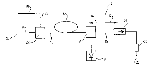
FIG. 1 is a schematic representation of a superfluorescent fiber
source according to a first embodiment of the invention.
2s FIG. 2 is a schematic representation of a superfluorescent fiber
source according to a second embodiment of the invention.
DESCRIPTION OF PREFERRED EMBODIMENTS OF THE INVENTION
With reference to FIGs. 1 and 2, a superfluorescent fiber source 6 is
3o shown according to preferred embodiments of the invention.

CA 02300396 2000-03-07
4
The fiber source 6 first includes a pump source 8 for generating pump
radiation, preferably a 980nm laser diode with a fiber output of
approximately 100mW (such pump lasers are sold commercially by SDL
Inc., Lasertron, Inc. and many others). The pump radiation is pigtailed to a
length of optical fiber 10. In the preferred embodiment, a single-mode fiber
is used. The two propagation directions in the length of optical fiber 10 will
be referred to as the forward direction 12 and the backward direction 14.
A region of the length of optical fiber 10 defines a gain medium 16.
When a pump signal is launched into such a gain medium 16, part of it is
to absorbed to stimulate the emission of Amplified Spontaneous Emission
(ASE) by the gain medium. This ASE is a broadband optical signal also
known as fluorescence. When this ASE signal has high output power
( > 1 mW), it is sometimes called superfluorescence. The ASE signal is
emitted in all directions with no distinctions. Some of this ASE signal,
is emitted in distributed directions, is captured and guided along the single-
mode fiber in both forward and backward directions. In the preferred
embodiment, the gain medium 16 is an erbium-doped fiber (such fibers are
sold commercially by INO, Lucent Technologies and many others). However,
this configuration works with any rare-earth doped fiber, depending on the
20 wavelength band output needed. Residual pump radiation will propagate in
the backward direction.
A first coupler 18 is provided, for coupling the optical pump source 8
to the length of optical fiber 10. The first coupler 18 ideally should be able
to selectively transmit the pump radiation in the backward direction 12 in
25 the optical fiber 10 and the superfluorescent radiation in the forward
direction 14. The first coupler 18 is disposed forward of the gain medium
16. In this manner, the gain medium 16 is pumped in counter-propagation,
and only the ASE signal is transmitted to the output 20 of the source. In the
preferred embodiment, standard 980/1550 WDM couplers are used to make
3o the discrimination between the pump and ASE signal (such couplers are sold
commercially by MP Fiberoptics Inc., Sumicem Ltd. and many others).

CA 02300396 2000-03-07
In order to recuperate both the backward and forward emissions at
the fiber source output 20, a mirror has to be used at the opposite end of
the source output 20. This reflector should preferably reflect only the ASE
signal, so as to avoid feedback of the pump signal and cause unstable
s power output behaviours of the source. For this purpose, a second coupler
22 is provided for coupling the pump radiation out of the length of optical
fiber 10. The second coupler 22 is disposed in the optical fiber 10 backward
of the gain medium 16, and selectively transmits the backward propagating
superfluorescence along a first path 24, and the pump radiation along a
io second path 26. A second 980/1550 WDM coupler is preferably used to
embody the second coupler 22. The first path 24 is preferably the
continuation of the length of optical fiber 10, and a reflector is disposed
therein for reflecting the backward propagating superfluorescent radiation in
the forward direction 12. The second path 26 is preferably a high
is attenuation fiber 28, to absorb the residual pump radiation and avoid
feedback to the pump laser. Any other type of absorbing means may
alternatively be used. For a 980 nm pump signal, a cobalt-doped or a Yb-
doped single-mode optical fiber is suggested as the high-attenuation fiber
(such fibers are sold commercially by INO, Fibercore Ltd. and many others).
zo The reflector may be embodied by any appropriate broadband mirror
30, as shown in FIG. 1. The mirror 30 can be any bulk mirror to which the
fiber 10 is butt-coupled. In the preferred embodiment, a thin-film high-
reflection coating, such as gold, is deposited on the fiber end (such fiber
pigtails with gold-coated fiber ends are sold commercially by INO, Seikoh
2s Giken and many others). Alternatively, a Bragg grating 32 photo-induced in
the first path 24 may be used. FIG. 2 shows an example of such an
embodiment where a grating reflecting a plurality of wavelengths is used,
but of course, any appropriate type of Bragg grating may be used. This
embodiment has the advantage of allowing a wavelength tailoring of the
30 output signal.

CA 02300396 2000-03-07
6
An optical isolator 34 is preferably installed right before the source
output 20 to keep this output stable by avoiding ASE signal feedback that
could cause lasing effects (such isolators are sold commercially by MP Fiber
Optics Inc., E-Tek Dynamics, Inc., and many others). Finally, the output of
the superfluorescent light source can be simply a singlemode fiber pigtail
with or without an optical connector 36.
Using the configuration suggested above and illustrated in FIG. 1, a
total output power from the superfluorescent fiber source 6 of 15.3dBm
(about 34mW) has been experimentally obtained, using a 100mW pump
signal. If the reflection discriminator was not installed on the
superfluorescent light source, the output power dropped to 13.4dBm (about
22mW). The output stability was better than 0.1 dB over 60 minutes using
this novel configuration.
Advantageously, the fiber source configuration according to the
present invention optimizes the power output while maintaining this optical
power output very stable in time. The proposed superfluorescent light
source configuration also has the advantages of using low-cost components
which are easy to assemble and do not require any alignment.
Of course, numerous changes could be made to the preferred
2o embodiment disclosed hereinabove without departing from the scope of the
invention as defined in the appended claims.

Representative Drawing
A single figure which represents the drawing illustrating the invention.
Administrative Status

2024-08-01:As part of the Next Generation Patents (NGP) transition, the Canadian Patents Database (CPD) now contains a more detailed Event History, which replicates the Event Log of our new back-office solution.

Please note that "Inactive:" events refers to events no longer in use in our new back-office solution.

For a clearer understanding of the status of the application/patent presented on this page, the site Disclaimer , as well as the definitions for Patent , Event History , Maintenance Fee  and Payment History  should be consulted.

Event History

Description Date
Time Limit for Reversal Expired 2019-03-07
Change of Address or Method of Correspondence Request Received 2018-12-04
Letter Sent 2018-03-07
Inactive: Correspondence - MF 2010-08-10
Inactive: IPC from MCD 2006-03-12
Grant by Issuance 2004-07-27
Inactive: Cover page published 2004-07-26
Pre-grant 2004-05-11
Inactive: Final fee received 2004-05-11
Notice of Allowance is Issued 2004-03-31
Letter Sent 2004-03-31
Inactive: Approved for allowance (AFA) 2004-03-02
Letter Sent 2002-07-29
Amendment Received - Voluntary Amendment 2002-06-17
Request for Examination Received 2002-06-11
Request for Examination Requirements Determined Compliant 2002-06-11
All Requirements for Examination Determined Compliant 2002-06-11
Application Published (Open to Public Inspection) 2001-09-07
Inactive: Cover page published 2001-09-06
Inactive: First IPC assigned 2000-05-09
Inactive: Filing certificate - No RFE (English) 2000-03-28
Letter Sent 2000-03-28
Application Received - Regular National 2000-03-27

Abandonment History

There is no abandonment history.

Maintenance Fee

The last payment was received on 2004-02-03

Note : If the full payment has not been received on or before the date indicated, a further fee may be required which may be one of the following

  • the reinstatement fee;
  • the late payment fee; or
  • additional fee to reverse deemed expiry.

Patent fees are adjusted on the 1st of January every year. The amounts above are the current amounts if received by December 31 of the current year.
Please refer to the CIPO Patent Fees web page to see all current fee amounts.

Owners on Record

Note: Records showing the ownership history in alphabetical order.

Current Owners on Record
INSTITUT NATIONAL D'OPTIQUE
Past Owners on Record
JOCELYN LAUZON
MICHEL BEGIN
Past Owners that do not appear in the "Owners on Record" listing will appear in other documentation within the application.
Documents

To view selected files, please enter reCAPTCHA code :


To view images, click a link in the Document Description column (Temporarily unavailable). To download the documents, select one or more checkboxes in the first column and then click the "Download Selected in PDF format (Zip Archive)" or the "Download Selected as Single PDF" button.

List of published and non-published patent-specific documents on the CPD .

If you have any difficulty accessing content, you can call the Client Service Centre at 1-866-997-1936 or send them an e-mail at CIPO Client Service Centre.

({010=All Documents, 020=As Filed, 030=As Open to Public Inspection, 040=At Issuance, 050=Examination, 060=Incoming Correspondence, 070=Miscellaneous, 080=Outgoing Correspondence, 090=Payment})


Document
Description 
Date
(yyyy-mm-dd) 
Number of pages   Size of Image (KB) 
Representative drawing 2001-08-22 1 4
Abstract 2000-03-06 1 23
Description 2000-03-06 6 267
Claims 2000-03-06 3 76
Drawings 2000-03-06 1 11
Courtesy - Certificate of registration (related document(s)) 2000-03-27 1 113
Filing Certificate (English) 2000-03-27 1 163
Reminder of maintenance fee due 2001-11-07 1 112
Acknowledgement of Request for Examination 2002-07-28 1 193
Commissioner's Notice - Application Found Allowable 2004-03-30 1 161
Maintenance Fee Notice 2018-04-17 1 181
Maintenance Fee Notice 2018-04-17 1 180
Fees 2003-01-16 1 30
Fees 2002-02-28 1 31
Fees 2004-02-02 1 28
Correspondence 2004-05-10 1 22
Correspondence 2010-08-09 1 45