Note: Descriptions are shown in the official language in which they were submitted.
CA 02300471 2000-03-10
IMPROVED DISTILLATION APPARATUS
Background of the Invention
This application is a continuation-in-part of US Application No. 08/649,013,
filed May
16, 1996, the disclosure of which is hereby incorporated herein by reference.
The present invention relates, in general, to a distillation device for
purification of water,
and more particularly to a compact, continuous flow distiller for supplying
pure drinking water.
The global need for safe drinking water is commonly recognized. Increasing
awareness of
health problems resulting from chemicals, bacteria and viruses in drinking
water is well
documented. Point of use water purification by distillation is the best and
only solution that
addresses all water contamination problems.
Many water distillers have been developed to provide pure drinking water;
however
certain problems still exist in the art. Examples of some ofthese problems
are: (1) some distillers
are not economical since they have unnecessary maintenance cost and a low
energy efl-iciency; (2)
some produce too much heat radiating into the air, particularly in small
offices and enclosed work
area; (3) most water distillers are noisy because they have electric cooling
fans that run at
inconvenient times; (4) some water distillers have attempted to overcome the
noise problem by
using water cooled condensers; however; in the prior art this has created
wastewater and required
f additional plumbing; and (5) some water distillers are difficult to maintain
in good operating
condition because of the difficulties encountered in cleaning sediment and
scale from the interior
of the distiller. In fact most water distillers require a substantial amount
of disassembly involving
multiple parts in order to fully clean the boiler. In many cases, the user
will not realize the
difficulty of this job until the water distiller fails to produce water up to
its rated capacity.
CA 02300471 2000-03-10
Numerous attempts have been made to facilitate the de-scaling and cleaning of
distillers,
but such attempts have not completely solved the problems in the prior art. In
most cases, such
attempts have resulted only in additional plumbing and additional components,
requiring
additional maintenance and increasing the cost of the unit. Thus, the cost and
maintenance of
these prior art devices is an acknowledged disadvantage.
To avoid the need to disassemble a distiller, many attempts have been made to
address the
cleaning problem by the use of after market chemicals for removing scale in
the boiler. However,
this has not eliminated the difficult periodic required manual cleaning for
proper maintenance of
distiller components. Further, the use of chemicals for this purpose is
expensive, a waste of
natural resources and ultimately adds to the already-serious pollution
problems.
Summary of the Invention
It is a primary object of the present invention to address environmental and
public health
concerns regarding the provision of safe drinking water in an effective
manner.
It is a further object of the invention to provide a water distiller that is
more economical
and energy efficient; for example; by effectively utilizing thermal energy
recovery to preheat water
to be treated; by operating during lower electrical rate periods; and by
eliminating wastewater.
It is another object of the invention to reduce heat radiation into the
surrounding air space,
particularly during normal office and working hours by operating primarily
during off work hours
and/or by evacuating heat to a remote location.
It is another object of the invention to provide a water distiller which is so
constructed as
to protect the condenser from being negatively affected by radiant heat from
the boiler or from the
boiler heat source by positioning the condenser below the boiler and heat
source.
It is another object of the invention to provide a water distiller that
reduces noise,
CA 02300471 2000-03-10
particularly during normal oi~ce and working hours, by eliminating a condenser
fan and/or by
operating during off work hours.
Yet another object of the invention is to provide a water distiller that may
use cooling
water to enhance heat exchange without creating wastewater, without requiring
plumbing and
connections to a house or building drain system, and without fouling cooling
water tubing by
utilizing distilled water from the reservoir for this purpose.
A still further object of the invention is to eliminate the di~culties and the
cost
encountered in cleaning sediment and scale from the interior of a boiler in a
distiller by providing a
removable boiler [in a distiller], which is seated within the housing in such
a way that it can be
easily removed for cleaning or replacement.
Another object of the invention is to provide a water distiller with a
protective control to
prevent the boiler from running dry, thus preventing scale.
Briefly, the present invention is directed, in its preferred embodiments, to a
water
distillation system which effectively addresses known problems in the art. The
embodiments are
directed to a continuous-flow distiller for permanent placement as a
freestanding unit in any
desired location. Such a device provides a continuous supply of pure water and
may, for
example, serve as a drinking fountain. The distiller includes a removable
heating vessel, or boiler,
which receives water that is to be treated, and a heater. The water in the
boiler is boiled by the
heater and the resulting steam or vapor is directed into, and through, a
condenser which provides
heat exchange surfaces to allow the steam to give off its heat through the
condenser walls, thereby
causing the steam to return to its water form. The lowermost end of the
condenser includes a
drain opening which directs the distilled water into a reservoir, or storage
container. The storage
container may be a stationary container for use, for example, in a water
fountain and a pump may
CA 02300471 2000-03-10
be provided to deliver water from this container.
In a preferred embodiment, the components are located within a housing having
a hinged
access lid at the top. The boiler is supported in the housing, as by suitable
angle brackets or other
supports, and may be in the form of an insulated double wall pot of stainless
steel. The boiler may
have a recessed area in its bottom with a drain tube and a drain spigot
connected to a drain hole
therein, extending downwardly and outwardly through a side hole in the
housing. The open top
of this boiler is closed and sealed by the housing lid, with an outlet steam
port in the lid being
connected to the inlet of a condenser. Preferably, the steam port is connected
by way of a suitable
pipeline, which passes through a raw water pre-heating chamber on its way to
the inlet of the
condenser. The raw water pre-heating chamber has an inlet and an outlet. Water
to be distilled is
supplied by way of a raw water inlet pipe to the pre-heating chamber inlet and
preheated raw
water is supplied from the chamber outlet to the boiler by way of a supply
pipe passing through
the hinged lid.
The outlet steam port and pipeline leads steam from the boiler to the inlet of
the
condenser, which in accordance with the present invention is located below the
boiler and below
the boiler heat source. The condenser, in a preferred embodiment, is water and
air-cooled and
includes a downwardly coiled, double-wall tubing or a smaller tube within a
larger tube. Cooling
water flows through the inner tube, while steam enters the larger outer tube
at a steam inlet and
flows downwardly as it condenses. The resulting distillate flows downwardly by
gravity to a
distillate outlet drain.
An enclosed container or storage vessel is located below the condenser and
receives water
from the distillate drain for storage and subsequent distribution through a
suitable outlet such as a
distillate spigot which may be located at any desired position on the housing.
If the spigot is
CA 02300471 2000-03-10
located above the storage container, a pump may be provided to deliver water
to it.
The smaller, cooling-water, inner tubing of the condenser extends downwardly,
through
the distillate drain at the lower end of the condenser, and is connected to an
outlet of a cooling-
water pump located, if so desired, at the bottom of the storage container. At
the upper end of the
condenser the cooling- water tubing exits the condenser through a hole in the
outer steam tubing
and extends downwardly through a hole in the top of the storage container and
terminates at a
cooling-water exit within the storage container.
The heating unit for the boiler preferably is a horizontal heating element
connected to the
lower end of a vertical heating unit stem, or support, that is connected to,
and extends
downwardly from, the lid.
A second embodiment of the invention is essentially the same as the first
embodiment;
however, in this case the condenser is of the heat exchange chamber or plates)
type having
cooling water circulated within and through the chamber or plate
configuration, as is known in the
industry. In any event, a cooling fan may be used, if desired, to enhance the
flow of ambient air
on the outside surfaces of the condenser.
A third embodiment is similar to the first and second embodiments, the
difference being
that the condenser is a typical coiled finned tubing type with a cooling fan
and a shroud. Also the
cooling-water pump and associated tubing have been eliminated.
A fourth embodiment is similar to the third embodiment, the difference being
the addition
of an exhaust pipe and hose to exhaust radiant heat from the condenser to a
remote location such
as outside a house or building.
Although four embodiments are illustrated, it will be understood that the
specific shape
and dimensions of the distiller can be varied to adapt it to a wide range of
applications in various
CA 02300471 2000-03-10
industries and at any desired location. It will become clear in the following
description that the
device provides a continuous flow water distiller with unique improvements and
advantages over
prior art including: (a) a significant increase in energy efficiency; (b) a
significant reduction of
heat in the surrounding air space; (c) significant reduction of noise; (d) the
elimination of
wastewater; and (e) the device is also unique in that it can be easily cleaned
by simply lifting the
lid of the housing and lifting the boiler out for cleaning purposes. /This
also facilitates replacement
of the boiler if necessary, and provides ready access to the heater unit for
adjustment or repair.
Brief Description of the Drawings
The foregoing, and additional objects, features and advantages of the present
invention
will be more fully understood by reference to the following detailed
description of preferred
embodiments thereof, taken in conjunction with the accompanying drawings, in
which:
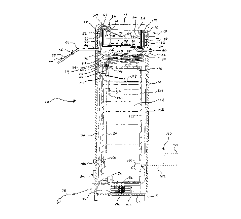
Fig. 1 is a cross sectional view of a preferred embodiment of the present
invention,
illustrating the components of a continuous mode distiller including a water
and air-cooled,
double tubing condenser;
Fig. 2 is a side elevation view of the distiller of Fig. 1 illustrating a
plurality of air vents.
Fig. 3 is a cross sectional view of a second embodiment of the present
invention,
illustrating a continuous mode distiller including a water and air-cooled
chamber or plate type
condenser;
Fig. 4 is a partial cross sectional layout view of a third embodiment of the
present
invention, illustrating the continuous mode distiller including a typical
coiled finned tubing (fins
not shown) condenser and a cooling fan; and
Fig. 5 is a partial cross sectional layout view of a fourth embodiment of the
present
invention, illustrating the continuous mode distiller of Fig.4 with the
addition of a remote exhaust
CA 02300471 2000-03-10
system.
Description of Preferred Embodiments
Turning now to a more detailed consideration of the present invention, there
is illustrated
in Fig. 1 a continuous mode water distiller generally indicated at 10. The
distiller includes a
housing 12 which may be generally cylindrical, if desired, and which is
preferably constructed of
metal or a durable plastic material. The housing 12 is supported by a stand 14
and is closed at its
bottom by a bottom wall 16 and at its top by a hinged lid 18. The lid 18
preferably is secured to
the top edge of housing 12 by one or more hinges 20 and may be opened by
pivoting it upwardly
and to the left, as viewed in Fig. 1, to provide access to the interior
components of the distiller 10.
The distiller 10 incorporates a removable double-wall boiler pot or vessel 22
that is
supported within the housing 12 by suitable brackets 24, for example. These
brackets 24 are
secured to the interior of the housing 12 and provide a seat for receiving
boiler 22 and holding it
securely in place within the housing. The boiler 22 incorporates, for example,
cylindrical, dual,
spaced side walls 26 and flat, circular, dual, spaced bottom walls 28
providing a thermally
insulative air space 30 between the dual walls and dual bottom. The boiler 22
is for receiving
water 32 which is to be distilled. If desired, the boiler 22 may further
incorporate a drain line 34
connected to a drain outlet 36 in a recessed area 38 in its bottom wall 28. A
drain spigot 40 at the
end of the drain line 34 may protrude through a drain opening 42 in the
housing 12 for draining
the water 32 from the boiler 22. The brackets 24 are so located as to position
the boiler 22 with
its open top edge engageable by a seal on the interior of lid 18 so that when
the lid is closed, the
boiler 22 is closed and sealed to prevent the escape of steam during the
distillation process:
Raw water to be boiled is supplied to the boiler 22 by way of a feed line 44
which is
connected to a pre-heating chamber 46 at a pre-heating inlet 48. The raw water
passes through a
CA 02300471 2000-03-10
heat exchange passageway in the pre-heating chamber 46, then through a
connector line 50
connected to a pre-heating chamber outlet 52. Connector line 50 extends
through lid 18 and
terminates above the interior of the boiler 22 at a nozzle 54. Feed line 44 is
connected by way of
a quick connect junction 56 to a water supply line 58 with the water flow
being regulated by a
valve 60. The level of water in boiler 22 is regulated by a controller 62
operated by a float 64, the
float serving to sense the water level, and the controller 62 serving to
regulate the flow of water
into the boiler 22 by way of a conventional valve at nozzle 54.
A heat source 70 is disposed within the boiler 22 and is connected to the
bottom of a
support such as a vertical stem 72, which in turn is mounted on and extends
downwardly from the
inside of the lid 18. The stem 72 and the heater 70 move with the lid, and the
heater is submerged
in water 32 when the lid 18 is closed. The heater 70 is connected by way of an
electrical cord 74
through control box 76 and cord 78 to a suitable source of power (not shown).
The control box
76 may be connected to an on-off control switch 80, and may include a
thermostat, circuit
breakers, and related controls for the heater.
Included in lid 18 is an outlet steam port 86 which has an inlet end 88 which
is positioned
above the boiler 22 when the lid 18 is closed for conveying steam from the
boiler 22 through a
steam tube 90 which passes through the pre-heating chamber 46 in route to the
inlet end 92 of a
condenser 94. The heat from the steam in tube 90 preheats the raw water being
supplied to the
boiler from chamber 46 through connector line 50.
The condenser 94, in the illustrated preferred embodiment of Fig. 1, includes
a
downwardly coiled double tubing comprising an outer tube 96 to provide a
passageway for steam
to condense into distillate and an inner tube 98 to provide a passageway for
cooling water to
travel in the opposite direction of the steam. A distillate drain terminal 100
at the lower end of
CA 02300471 2000-03-10
the outer tubing 96 directs distilled water into a storage container 102
supported within the
housing 12. The container 102 receives and stores distilled water 104 from
condenser 94 and is
supported within housing 12 by a suitable base 106. The water storage
container 102 may be of a
suitable plastic material and incorporates a level control float 108 connected
to a heater control
switch 110 for switching the heater 70 on and off in response to the water
level in the container
102. Switch 110 is connected in series in power line 74 for this purpose, and
enables the heater
70 to automatically switch on when the water level in the storage container
102 falls below a set
level.
The distillate drain terminal 100 is spaced slightly above an inlet 114 in the
top wall 116 of
storage container 102, the spacing between drain 100 and inlet 114 serving as
a gas vent I 18 for
the system to provide equalization of pressure in the condenser 94 and in the
storage container
102. If desired, an air filter 119 may be provided around the vent 118 to
prevent entry of
contaminates into the container 102.
A cooling water pump 130 located, for example, in a suitable housing mounted
on the
bottom wall 132 of the storage container 102 is provided to deliver cooling
water from the
storage container upwardly through a cooling water delivery line 134. The pump
130 supplies
water to the lower end of the inner tubing 98 of the condenser 94 wherein it
is conveyed through
the condenser in the opposite direction of the flow of steam, thus providing
excellent heat
exchange within condenser 94. A cooling water return tine 136 connected to an
inner tube exit
port 13 8, located near the inlet end 92 of the outer tubing 96, extends
downwardly through a
return port 140 in the top wall 116 of container 102 to a cooling-water
terminal 142 within
container 102 to provide a return passageway for the cooling water. If
desired, an external water
source may be used for cooling, but the use of distilled water from container
102 is preferred,
CA 02300471 2000-03-10
since this water is clean and will not foul the cooling tube.
A timer control 144 may, if desired, be in line with cord 74 to provide power
to the heat
source 70 (and cooling water pump 130 of Figs. 1 & 3) only during
predetermined time periods;
for example, between six PM and six AM, to provide a distiller that eliminates
noise and radiant
heat from the distiller in an office or work place during normal working
hours. This also provides
a distiller that operates in off peak power demand periods, thus taking
advantage of cheaper
electric rates and may negate a need for an upgrade in wiring or power source
capacity. This also
provides a distiller that assures substantial replacement of water in its
storage container 102 thus
preventing the stored water from becoming stale or stagnant.
If desired, a low water sensor 1 SO may be located, for example, on a side
wall 152 of the
storage container 102 to sense an extreme low water level in container 102,
and may be
connected to the controller 76 to provide power to the heater 70 (and pump 130
of Figs. 1 & 3)
to bypass the timer control 144 to provide distiller operation during times
when extra production
is required.
Water in the storage container 102 is delivered to a suitable outlet spigot
151 which may
be connected by way of water line 153 to a pump 154 located, for example, in a
suitable housing
mounted on the side wall 152 of the container 102. It will be understood that
in the alternative,
the pump 154 can be mounted on the top wall 116 of the container 102 or, if
desired, the spigot
1 S 1 can be mounted directly into the side wall 152 of the container 102 near
the bottom thereof.
In the event an air cooled condenser is used, as will be described with
respect to Figs. 4 and 5,
pump 154 may, if desired, be mounted on the bottom wall 130 of container 102.
In yet another alternative, the distiller 10 may provide water to a remote
delivery system,
indicated in phantom at 160 (Fig. 1), wherein pump 154 may be connected by
suitable pipeline(s),
CA 02300471 2000-03-10
indicated by dotted lines) 162, to one or more remote spigots 164, which may
be located at
remote locations) such as on counter top(s), in office(s), and/or in
hallway(s).
If desired, a water cooling system 170 may be disposed within the base 106
below the
storage container 102 for cooling the water 104 in the storage container 102,
in known manner.
Also, if desired, a filler 172 with a filler cap 174 may be located just below
lid 18 between
the boiler 22 and the housing 12. The filler may be connected to a nipple 176,
which may be
screwed through a hole in the top wall 116 of storage container 102, by way of
a filler line 178 to
provide a passageway for initially introducing a small amount of distilled
water into storage
container 102 for providing start up water for the cooling water pump 130
(Figs. 1 & 3).
As best illustrated in Fig. 2, a number of air inlet and outlet vents 190 are
provided in the
housing 12 to permit a free flow of air through the water cooling system 170
and through the
condenser 94, with air entering the vents below the condenser 94 and passing
upwardly through
the condenser before exhausting through exit vents located above the
condenser.
Fig. 3 illustrates the distiller 10 of Fig. 1 having a water and air-cooled
chamber or plates) ,
type condenser 200 instead of the double tubing condenser 94. The primary
difference is that the
chamber or plates) 202 replaces the outer tubing 96 of Fig. 1.
Fig. 4 illustrates the distiller 10 of Fig. 1 having a typical air-cooled,
condenser 204
including coiled, finned tubing 206, a fan 208 and a shroud 210 replacing the
water and air-cooled
condenser 94 and the cooling water pump 130 system of Fig. 1. As seen in Fig.
4 the fan 208
may be mounted on the top wall 116 of the storage container 102 below the
coiled finned tubing
206. For clarity, the fins on the tubes are not shown. The shroud 210,
preferably comprising a
suitable light weight plastic material, is connected to the interior of the
housing 12 above the inlet
air vents 190 (Fig. 2) and is open at its top to direct air flow through
finned tubing 206.
11
CA 02300471 2000-03-10
Fig. 5 illustrates the distiller 10 of Fig.4 with the addition of a remote
exhaust system 214
including an exhaust pipe 216, which may comprise a light weight plastic pipe,
connected to the
open upper end of the shroud 210 and protruding through the side of the
housing 12. A vent hose
218, which may comprise a light weight flexible hose similar to a dryer vent
hose used for a
typical clothes dryer, is connected to the protruding end of the exhaust pipe
216 and provides a
passageway for conveying hot air from the finned tubing 206 to a remote
location such as outside
of a house or building.
In operation, the present invention is a fully automatic water distiller. The
water distiller
illustrated in Fig. 1 is a simple device which is installed simply by
connecting raw water feed
line 58 to inlet line 44 of the device by means of quick connect fastener 56
and by opening valve
60 on the raw water line 58. (For the water and air-cooled condenser 94 of
Fig. 1 , and the
condenser 200 of Fig. 3, a small amount of distilled water is poured into the
storage container 102
through filler 172 to provide start up water for the cooling water pump 130).
The distiller 10 is
then turned on to provide electric power from the circuit control box 76 to
the heater 70 (and to
the cooling water pump 130, of Figs. 1 & 3) as raw water to be distilled flows
into the boiler 22.
When the water 32 in boiler 22 reached a desired level, automatic controller
62 turns off the water
supply. The heat source 70 then boils the water 32 in boiler 22 and the
resulting steam is directed
through exit port 88 and through the steam tube 90, which passes through pre-
heating chamber
46, to condenser 94, where the steam condenses into distilled water. This
distilled water flows by
gravity into storage container 102. Raw water from inlet line 44 passes
through the pre-heating
chamber 46, where it is pre-heated by steam tube 90 prior to entering the
boiler 22 through
connector line 50.
When the distilled water reaches a predetermined level in storage container
102, level
12
CA 02300471 2000-03-10
control float 108 operates heater control switch 110 to break the circuit to
the heater 70 (and
cooling water pump 130 of Figs. 1 & 3). When the distilled water level in
container 102 is
reduced to a predetermined level, the float 108 signals the control switch 110
to close the circuit
to the heater 70 (and pump 130 of Figs. 1 & 3) to thereby resume boiling water
in boiler 22 to
produce additional distilled water. This cycle is fully automatic, with the
two float switches
maintaining the desired water level in the boiler 22 and in the storage
container 102. The
compressor 170 cools the distilled water in the storage container 102 to a
desired temperature and
pump 154 delivers water on demand from container 102 to spigot 151 and or to
remote spigots)
164.
The lid 18 on the boiler 22 is connected to the housing 12 by suitable hinges)
20, so that
the housing 12 can be opened for ready access to the boiler 22 and other
interior components
such as the heater 70. The boiler 22 can be simply lifted out of the housing
12 to permit easy
cleaning and maintenance. The simple and easy removal of the boiler 22 is
possible because the
boiler 22 is independently seated on support brackets 24 rather than being
mounted to the side
wall of the housing 12. Thus the boiler 22 is a totally separate and
independent part. The need
for cleaning the boiler 22 is minimized because the level of the raw water 32
is automatically
maintained, thereby eliminating the build up of baked-on scale and chemical
deposits. The boiler
22 may also have a drain 34, if desired, to periodically drain the water 32
from the boiler 22 to
flush out the impurities left suspended in the water 32 during the operation
of the distiller 10.
The timer control 144 may provide power to the heater 70 (and cooling water
pump 130
of Figs. 1 & 3) only during predetermined time periods; for example, between
six PM and six
AM, to limit the normal distillation operation to a time when an office or
work place is not
13
CA 02300471 2000-03-10
occupied, thus eliminating noise and radiant heat during normal working hours.
This also
substantially increases the energy e~ciency of the distiller 10 because: (a)
the heater 70 (and
pump 130 ofFigs. 1 & 3) are not continuously going on and offin response to
the heater control
switch 110; (b) the water 32 in the boiler 22 does not have to be continuously
re-heated and the
incoming raw water is always pre-heated in the pre-heating chamber 46 by steam
tube 90; and
(c) the heater 70 (and cooling water pump 130 of Figs. 1 & 3) only operate
during offpeak power
demand periods, thus taking advantage of cheaper electric rates and may negate
a need for an
upgrade in wiring or power source. Also by allowing the level of the water 104
in storage
container 102 to go down substantially during day time consumption and
completely refilling it at
night prevents the stored water in container 102 from becoming stale or
stagnant.
The low water sensor 150 senses an extremely low water level in container 102,
and
allows power to the heater 70 (and pump 130 of Figs. 1 & 3) to bypass the
timer control 144,
thus providing operation during times when extra production of pure water is
required.
The above describes the operation of the four illustrated embodiments of the
invention
except for their differences in condensing systems and condenser cooling
systems. The following
describes these differences.
As illustrated in Fig. 1, the distiller 10 includes a water and air-cooled,
downwardly coiled,
double tubing condenser generally indicated at 94 and the cooling water pump
130. In operation,
power is provided to pump 130 and to the heater 70 (and if desired, to a
condenser cooling fan
which is not shown in Figs. 1 & 3) at the same time. Steam from the boiler 22
enters the upper
end of outer tubing 96 of condenser 94 at inlet 92 and travels downwardly
therein toward
distillate drain terminal 100 at the lower end of outer tubing 96. At the same
time, cooling water
pump 130 in storage container 102 delivers cooling water upwardly through
cooling water ,
14
CA 02300471 2000-03-10
delivery line 134 to the lower end of the inner tubing 98 wherein it is
conveyed in the opposite
direction of the steam in the outer tubing 96 thus providing excellent heat
exchange within
condenser 94. The cooling water exits the inner tubing 98 at exit port 138,
located near the inlet
end 92 of the outer tubing 96, and flows downwardly through return line 136 to
cooling water
terminal 142 within container 102, providing a return passageway for the
cooling water. During
this condensing process the steam in outer tubing 96 gives off its heat to the
ambient air and to
the cooling water in inner tubing 98. The resulting distilled water within the
outer tubing 96 and
outside of the inner tubing 98 flows by gravity into the storage container
102. If desired, a fan
may be used to enhance air movement (for example, as illustrated in Figs. 4 &
5).
The second embodiment (Fig. 3) of the invention operates in the same way as
the first
embodiment (Fig. 1), the difference being that the condenser 200 is of the
chamber or plates)
type instead of the outer and inner tubing type of the first embodiment (Fig.
1 ).
The third embodiment (Fig. 4) of the invention operates substantially the same
as the first
and second embodiments (Figs. 1 & 3), the difference being that the condenser
204 is only air-
cooled. Steam from the boiler 22 is conveyed downwardly through the typical
finned tubing 206.
Fan 208 forces cooling-air through shroud 210 to enhance heat exchange for the
finned tubing
206 during the condensing process of the steam and the resulting distilled
water flows by gravity
into the storage container 102.
The fourth embodiment (Fig. 5) of the invention is the same as the third
embodiment (Fig.
4), with the addition of remote exhaust system 214. The fan 208 forces cooling-
air through
shroud 210 to enhance heat exchange for the finned tubing 206. During the heat
exchange
operation the cooling-air becomes warm. This warm air is conveyed through
exhaust pipe 216
CA 02300471 2000-03-10
and vent hose 218 to a remote location such as outside of a house or building.
Thus, it will be seen that the water distiller of the present invention is
unique and provides
numerous improvements and advantages over the prior art. The distiller is well
suited for use in a
wide variety of locations, including dentist offices, hospitals, homes,
schools, restaurants,
cafeterias, business offices, and the like, as may be desired.
Although the invention has been described in terms of preferred embodiments,
it will be
understood that these are exemplary and that the scope of the invention is
limited only by the
following claims.
16