Language selection

Search

Patent 2300472 Summary

Third-party information liability

Some of the information on this Web page has been provided by external sources. The Government of Canada is not responsible for the accuracy, reliability or currency of the information supplied by external sources. Users wishing to rely upon this information should consult directly with the source of the information. Content provided by external sources is not subject to official languages, privacy and accessibility requirements.

Claims and Abstract availability

Any discrepancies in the text and image of the Claims and Abstract are due to differing posting times. Text of the Claims and Abstract are posted:

  • At the time the application is open to public inspection;
  • At the time of issue of the patent (grant).
(12) Patent Application: (11) CA 2300472
(54) English Title: NON-TIPPABLE POP-UP CAUTION SIGN
(54) French Title: PANNEAU AVERTISSEUR STABLE RESSORT
Status: Deemed Abandoned and Beyond the Period of Reinstatement - Pending Response to Notice of Disregarded Communication
Bibliographic Data
(51) International Patent Classification (IPC):
  • G09F 15/00 (2006.01)
(72) Inventors :
  • YOUNG, RONALD SCOT (United Kingdom)
  • GLENDENNING, RONALD STUART (United Kingdom)
(73) Owners :
  • SCOT YOUNG RESEARCH
(71) Applicants :
  • SCOT YOUNG RESEARCH (United Kingdom)
(74) Agent: SMART & BIGGAR LP
(74) Associate agent:
(45) Issued:
(22) Filed Date: 2000-03-08
(41) Open to Public Inspection: 2001-03-21
Examination requested: 2000-03-08
Availability of licence: N/A
Dedicated to the Public: N/A
(25) Language of filing: English

Patent Cooperation Treaty (PCT): No

(30) Application Priority Data:
Application No. Country/Territory Date
9922189.7 (United Kingdom) 1999-09-21

Abstracts

English Abstract


A warning sign comprises two parts 10, 11 pivotably connected together
at their upper ends and having ground contacting foot portions 13 at their
lower ends.
The two parts are pivotable between a first storage position in which the two
parts are
arranged in side-by-side relationship and a second operative position in which
the two
parts are at an angle to one another so that, with the foot portion or
portions of one
part spaced from the foot portion or portions of the other part, the sign will
be self
supporting on the ground. Detent means 16, 17 are provided for releasably
retaining
the two parts in said second position.
There is also disclosed a third pop-up part (see Figure 4) and means for
releasably supporting the pop-up part in a raised position.


Claims

Note: Claims are shown in the official language in which they were submitted.

-6-
CLAIMS
1. A warning sign comprising two pans pivotably connected together at their
in use upper ends and having ground contacting foot portions at their in use
lower
ends, said two parts being pivotable between a first storage position in which
said two
pans are arranged in side-by-side relationship and a second operative position
in
which said two parts are at an angle to one another so that, with said foot
portion or
portions of one pan spaced from said foot portion or portions of the other
pan, the
sign will be self-supporting on the ground, and detent means for releasably
retaining
the said two parts in said second position.
2. A warning sign as claimed in Claim 1, where said detent means comprises
at least one projection and at least one corresponding aperture or recess,
said
projection being arranged to fit in said aperture or recess as a snap or
friction fit
when said two pans are in said second position.
3. A warning sign as claimed in Claim 2, wherein each part has one said
projection which cooperates with one said corresponding aperture or recess
formed
in the other part.
4. A warning sign as claimed in Claim 1, further
comprising a third part slidably adjustable relative to said first and second
parts and
means for releasably supporting said third part in a raised position relative
to said

-7-
first and second pans when said first and second parts are in said second
position.
5. A warning sign as claimed in Claim 4, wherein said third part is only
releasable from its said raised position by moving said first and second pans
from
said second position.
6. A warning sign as claimed in Claim 4 , wherein said releasable support
means comprises first and second decent means, said third part being
releasably
supported in a raised position by said first detent means and being releasably
supported in a lowered position by said second decent means.
7. A warning sign as claimed in Claim 6, wherein said first and second detent
means comprise slots and projections formed in or on said third
part and at least one of said first and second parts.
8. A warning sign comprising two parts pivotably connected together at their
in use upper ends and having ground contacting foot portions at their in use
lower
ends, said two parts being pivotable between a first storage position in which
said two
parts are arranged in side-by-side relationship and a second operative
position in
which said two parts are at an angle to one another with said toot portion or
portions
of one pan spaced from said foot portion or portions of the other part so that
said
sign is self-supportable on the ground, a third part which is slidably
adjustable
relative to said first and second parts, and means for releasably supporting
said third

-8-
part in a raised position relative to said first and second parts when said
first and
second parts are in said second position.
9. A warning sign as claimed in Claim 8, wherein said third part is only
releasable from said raised position by moving said first and second parts
from said
second position.
10. A warning sign as claimed in Claim 8, wherein said releasable support
means comprises first and second detent means, said third part being
releasably
supported in a raised position by said first detent means and being releasably
supported in a lowered position by said second detent means.
11. A warning sign as claimed in Claim 10, wherein said first and second
decent means comprise slots and projections formed in or on said
third part end at least one of said first and second parts.
12. A warning sign as claimed in Claim 8 , wherein said third
part is resiliently flexible.

Description

Note: Descriptions are shown in the official language in which they were submitted.


CA 02300472 2000-03-08
29386-Z
-1-
NON-TIPPABLE POP-UP CAUTION SIGN
This invention relates to a warning sign particularly but not exclusively for
use on wet floors in public places.
According to a first aspect of the present invention there is provided a
warning sign comprising two parts pivotably connected together at their in use
upper
ends and having ground contacting foot portions at their in use lower ends,
the two
parts being pivotable between a first storage position in which the two parts
are
arranged in side-by-side relationship and a second operative position in which
the two
parts are at an angle to one another so that with the foot portion or portions
of one
part spaced from the foot portion or portions of the other part, the sign will
be self-
supporting on the ground, and detent means for releasably retaining the two
pans in
the second operative position.
Preferred and/or optional features of the first aspect of the invention are
set
forth in Claims 2 to 7 inclusive.
According to a second aspect of the invention there is provided a warning
sign comprising two parts pivotably connected together at their in use upper
ends and
having ground contacting foot portions at their in use lower ends, the two
parts being
pivotable between a first storage position in which the two parts are arranged
in side-
by-side relationship and a second operative position in which the two parts
are at an

CA 02300472 2000-03-08
_7_
angle to one another with the foot portion or portions of one part spaced from
the foot
portion or portions of the other part so that the sign will be self-supporting
on the
ground, a third part which can be raised or lowered relative to the first and
second
parts and means for releasably supporting the third part in a raised position
relative
to the first and second parts when the first and second parts are in said
second
position.
Preferred and/or optional features of the second aspect of the invention are
set forth in Claims 9 to 11.
The invention will now be more particularly described by way of example,
with reference to the accompanying drawings, in which:
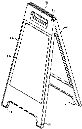
Figure 1 is a perspective view showing one embodiment of a warning sign
according to the first aspect of the invention, in an operative position,
Figure 2 is a fragmentary perspective view showing a hinge between first
and second parts of the warning sign shown in Figure 1,
Figure 3 is a fragmentary perspective view showing the upper part of the
first and second parts of the warning sign in a storage position,
Figure 4 is a vertical section taken between the first and second parts of the
warning sign but including also a third part which can be raised or lowered
relative

CA 02300472 2000-03-08
-3-
to the first and second parts, and
Figure 5 is a section taken along line V - V of Figure 4.
, Referring to the drawings, there is shown therein a warning sign which, for
example, can be used to caution the general public in a public place that a
potential
hazard exists in the vicinity of the sign, such as a wet floor or maintenance
work in
a restaurant, hospital, train station and such like. The warning sign
comprises first
and second parts 10 and 11 pivotably connected together by hinges 12 at the in
use
upper ends of the two parts 10 and 11 for movement between a first storage
position
in which the two parts lie parallel in a side-by-side relationship (see Figure
3) and a
second operative position in which the two parts are at an angle to one
another (see
Figure 1). Each part 10, 11 has feet 13 at its in use lower end so that when
the parts
10 and 11 are in the second operative position, the feet will support the sign
in an
upright position as shown in Figure 1.
Each part 10 and 11 has a recess 14, for receiving a caution sign, and a
hand hole 15.
As best seen in Figure 3, each part 10, 11 has a projection 16 at the upper
end of its inner face above the hinges 12 that securely releasably engages an
aperture
or recess 17 in the other part 11, 10 when the two parts 10 and 11 are in the
second
operative position. The projections 16 are a snap or friction fit in
corresponding
apertures or recesses 17 to allow the two parts to retain the second operative
position,

CA 02300472 2000-03-08
-4-
thereby reducing a tendency for the sign to collapse and/or fall over when
impacted.
As shown in Figures 4 and 5, the sign also comprises a third "pop-up" part
18. This third part 18 comprises a head portion 19 having the caution sign on
each
of its two major faces and a stem portion 20 which, when the first and second
parts
and 11 are in the first storage position, is slidable therebetween allowing
the third
part 18 to be adjusted between a lowered position in which the head portion 19
is just
above the upper ends of the first and second parts 10 and 11, and a second
raised
position.
The stem portion 20 has two pairs of recesses 21. The recesses of each
pair are horizontally aligned when the sign is in an upright position and the
two pairs
of recesses 21 are spaced vertically from one another. When the warning sign
is in
the second operative position, these recesses 21 receive projections 22 formed
on each
of the first and second pans 10 and 11. This allows the third part 18 to be
securely
supported in the raised (or lowered) position. The third part 18 can only be
released
from its raised (or lowered) position relative to the first and second parts
10 and 11
by moving the first and second parts from the second operative position, thus
releasing the projections 22 from the recesses 21.
Typically, all parts are formed of plastics material with the third part 18
preferably being resiliently flexible in a direction parallel to the ground on
which the
warning sign is erected. Due to this flexibility and the secure support of the
third
part 18 at the recesses 21 when in the operative position, stability of the
warning sign

CA 02300472 2000-03-08
-5-
is increased due to the realisation of a "pendulum" effect that allows
reversal of
momentum on impact of the third part 18, i.e. when a person accidently knocks
the
caution sign with a shoulder bag, for example, thus resulting in little or no
relative
movement of the warning sign subsequent to impact.

Representative Drawing
A single figure which represents the drawing illustrating the invention.
Administrative Status

2024-08-01:As part of the Next Generation Patents (NGP) transition, the Canadian Patents Database (CPD) now contains a more detailed Event History, which replicates the Event Log of our new back-office solution.

Please note that "Inactive:" events refers to events no longer in use in our new back-office solution.

For a clearer understanding of the status of the application/patent presented on this page, the site Disclaimer , as well as the definitions for Patent , Event History , Maintenance Fee  and Payment History  should be consulted.

Event History

Description Date
Time Limit for Reversal Expired 2006-03-08
Application Not Reinstated by Deadline 2006-03-08
Inactive: Abandoned - No reply to s.30(2) Rules requisition 2005-04-01
Deemed Abandoned - Failure to Respond to Maintenance Fee Notice 2005-03-08
Inactive: S.30(2) Rules - Examiner requisition 2004-10-01
Letter Sent 2004-04-15
Reinstatement Requirements Deemed Compliant for All Abandonment Reasons 2004-03-19
Deemed Abandoned - Failure to Respond to Maintenance Fee Notice 2004-03-08
Letter Sent 2001-04-12
Application Published (Open to Public Inspection) 2001-03-21
Inactive: Cover page published 2001-03-20
Inactive: Single transfer 2001-03-16
Inactive: Office letter 2000-06-29
Inactive: First IPC assigned 2000-05-09
Request for Priority Received 2000-04-12
Inactive: Courtesy letter - Evidence 2000-04-04
Inactive: Filing certificate - RFE (English) 2000-03-29
Application Received - Regular National 2000-03-28
Request for Examination Requirements Determined Compliant 2000-03-08
All Requirements for Examination Determined Compliant 2000-03-08

Abandonment History

Abandonment Date Reason Reinstatement Date
2005-03-08
2004-03-08

Maintenance Fee

The last payment was received on 2004-03-19

Note : If the full payment has not been received on or before the date indicated, a further fee may be required which may be one of the following

  • the reinstatement fee;
  • the late payment fee; or
  • additional fee to reverse deemed expiry.

Patent fees are adjusted on the 1st of January every year. The amounts above are the current amounts if received by December 31 of the current year.
Please refer to the CIPO Patent Fees web page to see all current fee amounts.

Fee History

Fee Type Anniversary Year Due Date Paid Date
Request for examination - standard 2000-03-08
Application fee - standard 2000-03-08
Registration of a document 2001-03-16
MF (application, 2nd anniv.) - standard 02 2002-03-08 2001-11-01
MF (application, 3rd anniv.) - standard 03 2003-03-10 2003-03-05
MF (application, 4th anniv.) - standard 04 2004-03-08 2004-03-19
Reinstatement 2004-03-19
Owners on Record

Note: Records showing the ownership history in alphabetical order.

Current Owners on Record
SCOT YOUNG RESEARCH
Past Owners on Record
RONALD SCOT YOUNG
RONALD STUART GLENDENNING
Past Owners that do not appear in the "Owners on Record" listing will appear in other documentation within the application.
Documents

To view selected files, please enter reCAPTCHA code :


To view images, click a link in the Document Description column (Temporarily unavailable). To download the documents, select one or more checkboxes in the first column and then click the "Download Selected in PDF format (Zip Archive)" or the "Download Selected as Single PDF" button.

List of published and non-published patent-specific documents on the CPD .

If you have any difficulty accessing content, you can call the Client Service Centre at 1-866-997-1936 or send them an e-mail at CIPO Client Service Centre.

({010=All Documents, 020=As Filed, 030=As Open to Public Inspection, 040=At Issuance, 050=Examination, 060=Incoming Correspondence, 070=Miscellaneous, 080=Outgoing Correspondence, 090=Payment})


Document
Description 
Date
(yyyy-mm-dd) 
Number of pages   Size of Image (KB) 
Representative drawing 2001-03-07 1 8
Abstract 2000-03-07 1 20
Claims 2000-03-07 3 91
Description 2000-03-07 5 143
Drawings 2000-03-07 3 57
Filing Certificate (English) 2000-03-28 1 163
Request for evidence or missing transfer 2001-03-11 1 108
Courtesy - Certificate of registration (related document(s)) 2001-04-11 1 113
Reminder of maintenance fee due 2001-11-12 1 112
Courtesy - Abandonment Letter (Maintenance Fee) 2004-04-14 1 175
Notice of Reinstatement 2004-04-14 1 166
Courtesy - Abandonment Letter (Maintenance Fee) 2005-05-02 1 174
Courtesy - Abandonment Letter (R30(2)) 2005-06-12 1 166
Correspondence 2000-03-28 1 14
Correspondence 2000-04-11 2 98
Correspondence 2000-06-28 1 7
Fees 2004-03-18 2 63