Note: Descriptions are shown in the official language in which they were submitted.
CA 02300593 2000-03-10
ROCK BIT NOZZLE AND RETAINER ASSEMBLY
TECHNICAL FIELD OF THE INVENTION
The present invention relates to a nozzle and retainer assembly for use in
rotary
cone earth boring bits. l:n one aspect, the present invention relates to a
nozzle and
retainer assembly that allows for a larger fluid passage in the nozzle and for
orientation of
the nozzle relative to thE; bit.
-1-
CA 02300593 2000-03-10
BACKGROUND OF 7CHE INVENTION
Earth boring bit; used for drilling holes in the earth are typically
classified into
two types: drag bits which have no moving parts and shear the formation (e.g.
polycrystalline diamond. compact (PDC) bits, diamond impregnated bits, etc.)
and rotary
cone bits which have one or more generally conic roller cones rotatably
mounted on the
bit body. The roller cones have cutting teeth and/or inserts extending
therefrom and
rotation of the bit body rotates the cones so that the cutting teeth and/or
inserts crush and
gouge the formation.
Both of these ty~~es of bits use nozzles mounted on the bit body to direct
drilling
1o fluid coming down the drill string to sweep the bottom of the borehole and
carry cuttings
back up the hole on the outside of the drill string. This fluid flow, or "bit
hydraulics",
serves three primary purposes: cutting removal, relief of chip hold down
pressure, and,
in the case of rotary cone bits, cleaning of the cones. T'he location and type
of the nozzles
used can greatly impact these purposes.
Location of the nozzles relative to the borehole bottom is especially relevant
to
rotary cone bits versus drag bits. Because the face of the drag bit body is
directly against
the formation, the nozzlf;s in a drag bit are readily located near the
borehole bottom by
mounting of a nozzle in a receptacle in the bit body. In contrast, the bit
body of a rotary
cone bit is disposed above the bottom of the formation by the rotary cones and
thus fluid
2o exiting from a nozzle recessed or flush with the bit body must travel a
significant distance
before impinging at or near the borehole bottom. Moving the nozzle exit closer
to the
hole bottom can generally improve chip removal by increasing the bottom hole
energy
and by improving the ab ility of the fluid to relieve chip hold-down
pressures.
_2_
CA 02300593 2000-03-10
One way the exit orifice of nozzles in rotary cone bits have been moved closer
to
the borehole bottom is by using steel tubes that extend from the bit body with
a wear-
resistant nozzle mounted in the end of the tube. These extended nozzle tubes
have the
advantage of being able to closely locate the exit orifice of the nozzle close
to the
borehole bottom; however, the extended tubes are susceptible to breaking. A
tube
breaking off of the bit effectively ends the run of that particular bit and
may require a
costly down hole fishin~; (retrieving) operation to remove the tube from the
bottom of the
borehole.
Another way that the exit orifice has been moved closer to the borehole bottom
is
to by the use of "mini-extended" nozzles. Conventional nozzles are generally
flush or
recessed from the outer ~~urface of the receptacle in the bit body in which
they are
mounted. Mini-extended nozzles have a portion which extends beyond the
receptacle in
which it is mounted but still are retained by conventional nozzle retention
means. With
reference to Figure 1, a conventional mini-extended nozzle 10 is shown mounted
in
~ 5 receptacle 12 defined in bit body assembly 14. Nozzle 10 defines passage
16 for the
direction of drilling fluid through the nozzle. Receptacle 12 conventionally
has a
standard inner diameter for a given size bit. Retainer 18 threads into
receptacle 12 at
threaded connection 24 and retains nozzle 10 in receptacle 12 by capturing
shoulder 20 of
nozzle 10 by ledge 22 exaending radially inward from retainer 18. Nozzle 10
seats on
2o shoulder 26 in receptacle; 12. Seal 28 seals between the outer surface of
nozzle 10 and
the inside of receptacle 12. Nozzle 10 is referred to as .a "mini-extended"
nozzle due to
the fact that the nozzle has portion 11 extending beyond receptacle 12. The
outer
diameter of portion 11 is smaller than the outer diameter of base portion 13
of nozzle 10
-3-
CA 02300593 2000-03-10
in order to extend beyond ledge :22 of retainer 18. The advantage of mini-
extended
nozzles is their relative durability and ruggedness compared to extended
tubes; however,
a mini-extended nozzle does not locate the nozzle orifice as close to the
borehole bottom
as an extended tube.
U.S. Patent No. 5,669,459 discloses a retention body for holding a mini-
extended
nozzle closer to the bore;hole bottom. This design has the advantage of better
protecting
the mini-extended nozzle during operation by extending a mild steel retention
body along
the portion of the nozzle; that extends beyond the body of the bit. By better
protecting the
nozzle, the orifice of the; nozzle c;an be moved closer to the borehole bottom
compared to
io a mini-extended nozzle mounted in a conventional receptacle while at the
same time
avoiding the potential breakage problems associated with extended tubes.
Thus for a rotary cone bit, the mini-extended nozzle can be used in a
conventional
receptacle for some extension, with a retention body of the '459 patent for
additional
extension, or with an extended tube for even more extension but with risk of
tube
;l s breakage.
In addition to location of the nozzle in the axial direction (i.e., distance
from
borehole bottom), the type of nozzle used impacts the goals of chip removal,
relief of
chip hold down pressure, and cone cleaning. More specifically, the nozzle
passageway
and orifice can effect bit hydraulics. U.S. Patent No. 5,494,124 (as well as
related patents
2o 5,632,349; and 5,653,298) discloses a type of nozzle with a passageway and
orifice
design that is purported vto provide advantages over other nozzles when used
in an earth
boring bit. Figures 1, 3, and 5 of the '124 patent show the shaped orifices
(slot 16, 46,
-4-
CA 02300593 2000-03-10
and 76, respectively) while Figures 2, 4, and 6 of the ' 124 patent show the
corresponding
internal passage 20, 50, 80, respectively.
With reference to Figure 2, an embodiment of nozzle 10' of the type disclosed
in
the ' 124 patent is shown in receptacle 12 with retainer 18 capturing end 21
of nozzle 10'.
Nozzle 10' is recessed from the opening of receptacle 12. Passage 16' has
transition zone
29 that transitions from passage 16' to orifice 31. The '124 patent teaches
particular
shapes of transition zone 29 and orifice 31 to achieve the desired fluid
characteristics for
the nozzle.
One disadvantage of the nozzle of the '124 patent is that its internal passage
16'
to must be much larger than that of a conventional nozzle to allow sufficient
room for the
desired short transition :one 29 with its high rate of inward taper to orifice
31, especially
for larger sized nozzle orifices. The standard receptacle 12 in a bit together
with the
retention means used to hold the nozzle in the receptacle limits the maximum
outer
envelope of the nozzle, and this together with the minimum acceptable wall
thickness of
the nozzle limits the maximum size of internal passage 16' of the nozzle.
Thus, for a
given receptacle 12, the maximum nozzle orifice size achievable by the '124
nozzle will
be appreciably less than that of a conventional nozzle. This is a disadvantage
because
standard drilling practicf;s often require larger nozzle orifices to reduce
the pressure drop
across the bit. The inability to accommodate larger nozzle orifices makes the
nozzles of
2:o the '124 patent less versatile and unable to be used in certain drilling
applications that
may require a pressure drop that is less than that available with the largest
'124 nozzle for
the particular receptacle in the bit.
-5-
CA 02300593 2000-03-10
This disadvantal;e of the ' 124 nozzle is compounded when it is desired to
take
advantage of the mini-extended nozzle concept by extending the end of the
nozzle
beyond the receptacle in which it is mounted. Retainer 18 used with mini-
extended
nozzle 10 in Figure 1 requires a reduced outer diameter of extended portion
11. This
reduced diameter even more severely restricts the maximum size of internal
passagel6'
of the ' 124 type nozzle of Figure 2 thus further reducing the maximum nozzle
exit orifice
size possible relative to a mini-extended nozzle with a conventional internal
passage.
Furthermore, the. nozzle of the '124 patent relies in part on a relatively
short
transition zone 29 to taper from passageway 16' to orifice 31. Passageway 16'
only
slightly tapers radially inward from interior end 19 to transition zone 29 and
thus
maintains a relatively large inner diameter compared to passageway 16 in
Figure 1.
Transferring passagewa;~ 16' to a mini-extended nozzle of Figure 1 can be seen
by the
dashed line in Figure 1 which represents extended passageway 16" for a nozzle
of the
type of the '124 patent. As can be seen the inner diameter of passageway 16"
is larger
~5 than the outer diameter of extended portion 11 at a point indicated at 17.
Thus, such an
extension is not possible; with retainer 18 of Figure 1.
While nozzles of the type of the '124 patent have been used with drag bits as
shown in Figure 2, they are not directly translatable to a rotary cone bit
without the
disadvantages discussed above. 'Therefore, a need exists for a nozzle and
retainer
ao assembly that allows for an increase in the size of the internal passage of
a mini-extended
nozzle so that the teachings of the '124 patent can be used in a mini-extended
design for a
range of nozzle orifice sizes comparable to that of conventional mini-extended
nozzles.
-6-
CA 02300593 2000-03-10
One teaching of the '124 is the generation of lower than hydrostatic pressure
zones on the hole bottom. In drilling applications, fluid is transmitted to
the hole bottom
via a drill string to remove cuttings from the hole bottom and transport them
back to the
surface through the annular space between the drill string and the hole wall.
Weighting
materials are typically added to the drilling fluid to ensure the bore hole
pressure is
greater than that of the bore pressure to ensure the integrity of the bore
hole. If the fluid
is under-weighted, causing the bore pressure to be less than the pore pressure
of the
surrounding formation, 'the hole can cave in and stick the drill string in the
hole which
causes costly hole deviations. However, if the hole pressure is too high, rock
bit
penetration rates are significantly reduced since the chips generated by the
cutters tend to
be held in the formation by the pressure differential across the hole
surfaces. The '124
nozzles are intended to l;enerate localized low pressure zones on the hole
bottom which
allows cuttings to lift from the hole bottom in these localized zones in the
presence of
global overburden pressures. To generate the localized low pressure zones, the
'124
:~ 5 nozzles are intended to generate :Lobes of flow which move the fluid
radially outboard
from the centerline of the nozzle. Because the flow from the '124 nozzles is
not
axisymmetric like that of nozzle 10 in Figure 1, a need exists to optimize the
rotational
position of the nozzles relative to the cones of a rotary cone bit.
Additionally, nozzles may have passages and/or asymmetric orifices that direct
2o the fluid at an angle. As fluid flows through an angled passage, it will
impart a rotational
force on the nozzle. Such nozzles must be able to be readily located at a
desired
rotational orientation ami/or locked against rotational forces from fluid flow
through the
bit. Thus a need exists for a nozzle and retainer assembly that allows for an
increase in
CA 02300593 2000-03-10
the size of the internal passageway of a mini-extended nozzle and provide for
rotational
location and/or locking of the nozzle relative to the bit body.
_g_
CA 02300593 2000-03-10
SUMMARY OF THE IfNVEN7.'ION
One aspect of thc; present invention provides a novel nozzle and retainer
assembly
that moves the engagement point between the nozzle and retainer radially
outward to
allow for additional cross-sectional area of the nozzle which in turn allows
for a larger
internal passage. In this aspect, a rotary cone earth boring bit is provided
that comprises
a bit body assembly with at least one rotary cone rotatably mounted on the bit
body
assembly. The bit body assembly defines at least one fluid bore therethrough
and a
generally cylindrical receptacle in communication with the fluid bore. The
receptacle has
an interior end defining .a seat shoulder, an open end opposite thereto, and a
generally
cylindrical inside surface:. A nozzle has a first end abutted against the seat
shoulder of
the receptacle and a second end opposite thereto. The nozzle has an outer
surface with a
stepped portion extending radially outward so as to define a first nozzle
shoulder spaced
from and facing toward ohe seat shoulder and a second nozzle shoulder facing
opposite
thereto. The nozzle defines a passage therethrough having a first end in
communication
with the fluid bore and a second end opposite thereto defining an orifice at
the second end
of the nozzle. A retainer sleeve is concentrically disposed about the outer
surface of the
nozzle and has an outside surface removably attached to the inside surface of
the
receptacle. The retainer sleeve has a first end engaged with the engagement
shoulder of
the rib so as to retain the nozzle in the receptacle and a second end opposite
thereto
toward the open end of the receptacle. An annular seal is located between the
seat
shoulder of the receptacle and the gland shoulder of the rib of the nozzle.
In another aspect of the present invention, a rotary cone earth boring bit is
provided that comprises a bit body assembly with at least one rotary cone
rotatably
-9-
CA 02300593 2000-03-10
mounted on the bit body assembly. The bit body assembly defines at least one
fluid bore
therethrough and a generally cylindrical receptacle in communication with the
fluid bore.
The receptacle has an interior end defining a seat shoulder, an open end
opposite thereto,
and a generally cylindrical inside surface. A nozzle has a first end abutted
against the
seat shoulder of the receptacle anal a second end opposite thereto extending
beyond the
open end of the receptacle. The nozzle defines a passage therethrough having a
first end
in communication with the fluid bore and an orifice end opposite thereto at
the second
end of the nozzle. The passage has a first cross-sectional area at the first
end, a second
cross-sectional area at a point axially coextensive with the open end of the
receptacle and
t o a third cross-sectional area at the orifice end. The second cross-
sectional area is at least
about 25% of the first cross-sectional area. The passage converges from the
second
cross-sectional area to the third cross-sectional area. A retainer removably
engages the
inside surface of the recc;ptacle and the nozzle to retain the nozzle in the
receptacle. The
retainer engages the noz:ale at a point that is between the seat shoulder and
the open end
~ 5 of the receptacle.
In another aspect of the present invention, a rotary cone earth boring bit is
provided that comprises a bit body assembly with at least one rotary cone
rotatably
mounted on the bit body assembly with the cone having a cone axis and a cone
surface
extending from a nose toward the center of the bit body to a gage side
opposite thereto.
2:o The cone surface has a plurality of cutting elements extending therefrom.
The bit body
assembly defines at leasl: one fluid bore therethrough and a generally
cylindrical
receptacle in communication with the fluid bore. The receptacle has an
interior end
defining a seat shoulder, an open end opposite thereto, and a generally
cylindrical inside
-10-
CA 02300593 2000-03-10
surface. A nozzle has a first end abutted against the seat shoulder of the
receptacle and a
second end opposite thereto extending beyond the open end of the receptacle.
The nozzle
defines a passage therethrough having a first end in communication with the
fluid bore
and an orifice end opposite thereto at the second end of the nozzle. The
internal passage
has an inside surface and the inside surface towards the second end of the
nozzle defines
at least one flute therein that slopes in a flute direction taward the center
of the nozzle as
it approaches the second end of the nozzle. A retainer removably engages the
inside
surface of the receptacle and the :nozzle to retain the nozzle in the
receptacle. The
retainer engages the nozzle at a point that is between the seat shoulder and
the open end
of the receptacle.
In another aspect of the present invention, a nozzle is provided that
comprises a
body with a generally cylindrical outer surface having a center axis and
defining a
longitudinal direction from a firsl: end to a second end opposite thereto. The
body defines
a passage therethrough from the first end to the second end of the nozzle. The
outer
surface defines a stepped portion located near the first end of the nozzle and
extending
radially outward and having a first nozzle shoulder spaced longitudinally from
the first
end and facing in the longitudinal direction toward the first end and a second
nozzle
shoulder opposite thereto facing in the longitudinal direction toward the
second end. The
outer surface of the nozzle at all points other than the stepped portion is
radially inward
2:0 of the stepped portion.
In another aspect of the present invention, a rotary cone earth boring bit is
provided that comprises a bit body assembly and at least one rotary cone
rotatably
mounted on the bit body assembly. The cone has a rotational axis and an outer
surface
-11-
CA 02300593 2000-03-10
with a plurality of cutting elements extending therefrom. The bit body
assembly defines
at least one fluid bore therethrough and a generally cylindrical receptacle in
communication with the fluid bore. The receptacle has an interior end defining
a seat
shoulder, an open end opposite thereto, and a generally cylindrical inside
surface. A
nozzle has a first end abutted against the seat shoulder of the receptacle and
a second end
opposite thereto. The nozzle defines a passage therethrough having a first end
in
communication with the fluid bore and an orifice end opposite thereto at the
second end
of the nozzle. The pass~~ge has an inside surface that, towards the second end
of the
nozzle, defines three or i:ewer flutes therein. Each flute slopes in a flute
direction toward
to the center of the nozzle <~s it approaches the second end of the nozzle.
The flute is
directed between about '~0 degrees to about 160 degrees or between about 200
degrees to
about 290 degrees from the radially outermost point of the receptacle in a
clockwise
direction
In another aspect of the present invention, a rotary cone earth boring bit is
provided that comprises a bit body assembly and at least one rotary cone
rotatably
mounted on the bit body assembly. The cone has a rotational axis and an outer
surface
with a plurality of cutting elements extending therefrom. The bit body
assembly defines
at least one fluid bore th~~rethrough and a generally cylindrical receptacle
in
communication with the fluid bore. The receptacle has an interior end defining
a seat
2:o shoulder, an open end opposite thereto, and a generally cylindrical inside
surface. A
nozzle has a first end abutted against the seat shoulder of the receptacle and
a second end
opposite thereto. The nozzle defines a passage therethrough having a first end
in
communication with the fluid bore and an orifice end opposite thereto at the
second end
-12-
CA 02300593 2000-03-10
of the nozzle. The passage has an inside surface that, towards the second end
of the
nozzle, defines a single :flute therein. The flute slopes in a flute direction
toward the
center of the nozzle as it approaches the second end of the nozzle. The flute
is directed
between about 60 degrec;s and about 3U0 degrees from the radially outermost
point of the
receptacle in a clockwise direction
-13-
CA 02300593 2000-03-10
BRIEF DESCRIPTIOhT OF THE DRAWINGS
Figure 1 is a cross-section of a prior art mini-extended nozzle and retainer
assembly mounted in a t>it;
Figure 2 is a cross-section of a prior art nozzle and retainer assembly
mounted in
a bit;
Figure 3 is a side view of a bit according to the present invention;
Figure 4 is a cro:;s-section of the preferred embodiment of the nozzle and
retainer
assembly of the present invention mounted in a bit and shown with orientation
tool;
Figure S is a per:~pective view of the nozzle of Figure 4;
1 o Figure 6 is an overlay of the nozzle of Figure 4 with the nozzle of Figure
1
comparing the two nozzles in the same size receptacle in a bit;
Figure 7A is a partial bottom view of a bit according to an embodiment of the
present invention;
Figure 7B is a crass-section of the nozzle of Figure 7A along line B-B;
Figure 8 is a partial bottom view of the bit of Figure 7A with the nozzle in a
different orientation;
Figure 9A is a partial bottom view of a bit according to another embodiment of
the present invention;
Figure 9B is a cross-section of the nozzle of Figure 9A along line B-B;
2o Figure 10 is a bottom view of the bit of Figure 9A with the nozzles in
different
orientations;
Figure 11 A is a partial bottom view of a bit according to another embodiment
of
the present invention;
- 14-
CA 02300593 2000-03-10
Figure 11B is a c;ross-section of the nozzle of Figure 11A along line B-B;
Figure 12 is a cross-section of an alternative embodiment of the nozzle and
retainer assembly of the present invention mounted in <~ bit;
Figure 13 is a perspective view of the nozzle of Figure 12;
Figure 14 is a cross-section of another alternative embodiment of the nozzle
and
retainer assembly of the present invention mounted in a bit and shown with an
alternative
orientation tool;
Figure 15A is an under side perspective view of an alternative embodiment of
an
orientation tool that can be used with the assembly of Figure 14;
Figure 15B is a bop side perspective view of the orientation tool of Figure
15A;
Figure 16A is a cross-section of another alternative embodiment of the present
invention mounted in a bit;
Figure 16B is a perspective view of Figure 16A;
Figure 16C is a perspective view of the nozzle of Figure 16A;
~ 5 Figure 17 is a cross-section of another alternative embodiment of the
present
invention mounted in a bit; and
Figure 18 is a cross-section of an alternative embodiment of a portion of the
bit
assembly of the present iinvention.
-15-
CA 02300593 2006-05-12
75674-28
DETAILED DESCRIPTION OF THE PREFERRED EMBODIMENT
With reference to Figure 3-5, the preferred embodiment of the present
invention is
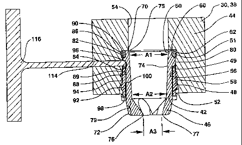
shown. Figure 3 shows bit 44 of the present invention with bit body assembly
30 having
legs 32 extending downward and threaded end 33 opposite thereto for attachment
to a
drill string. Rotary cones 34 are rotatably mounted to bit body assembly 30 as
is known
in the art for contacting borehole bottom 36. Nozzle and retainer assembly 40
is mounted
in receptacle 42 of bit body assembly 30. Bit body assembly 30 also has boss
38
extending radially outward to locate receptacle 42 radially outward and
axially toward
borehole bottom 36. Nozzle 46 is captured in receptacle 42 by retainer 48
which is
removably mounted within receptacle 42 to engage nozzle 46 at engagement point
49,
As can be seen, by virtue of rotary cones 34 engaging borehole bottom 36, bit
body
assembly 30 is disposed above borehole bottom 36 in contrast to a drag bit
where the bit
body directly engages the borehole bottom.
One aspect of this embodiment of the present invention involves moving
engagement point 49 between retainer 48 and nozzle 46 radially outward to
allow more
space for internal passage 74 as may be required by nozzles of the type
disclosed in U.S.
Patent Nos. 5,494,124; 5,632,349; and 5,653,298.
These types of nozzles require a larger internal passage relative to
conventional nozzles to achieve comparable nozzle sizes. The present invention
provides
2o more space for larger internal passages in the nozzle to allow them to be
used with a
comparable range of nozzle sizes as conventional nozzles while still allowing
them to be
mounted in standard nozzle receptacles in the bit body.
-16-
' CA 02300593 2000-03-10
Receptacle 42 is located i.n bit body assembly 30. Receptacle 42 can be
located in
bit body assembly 30 by many methods. Examples of these methods include
machining
receptacle 42, welding i:n a pre-machined sleeve such as that disclosed in
Patent
5,538,093 or by attaching a tube such as that disclosed in U.S. Patent No.
5,669,459 that
moves receptacle 42 closer to borehole bottom 36. An,y of these methods of
installation
would provide a nozzle receptacle 42 that by definition is considered a part
of bit body
assembly 30 for purposes of this invention. Receptacle 42 extends from
interior end 51
defining seat shoulder 50 to open end 52 and is in communication with fluid
bore 54 of
bit 44. Receptacle 42 is generally cylindrical with inside surface 56. At
least a portion of
! o inside surface 56 define; receptacle threads 58. Inside surface 56 also
defines annular
seal groove 60 at interior end 51 with gland shoulder 62 facing shoulder 50.
Nozzle 46 is at lf;ast partially disposed in receptacle 42. Nozzle 46 has
first end
70 abutted against shoulder 50 and second end 72 extending beyond open end 52
of
receptacle 42. Nozzle 46 has internal passage 74 that extends through nozzle
46 from
~ 5 first end 70 to second end 72. Internal passage 74 is in communication
with fluid bore 54
and exits second end 72 at orifice 76. Nozzle 46 has outer surface 78 of which
a
substantial portion is generally cylindrical. Outer surface 78 defines stepped
portion 80
extending radially outward to define first nozzle shoulder 82 facing and
disposed from
shoulder 50 and second nozzle shoulder 84 facing generally opposite first
nozzle shoulder
a:o 82. First nozzle shoulder 82 is preferably at generally t:he same axial
location as gland
shoulder 62 so that annular gland 86 is defined between shoulder 50 as one
side and first
nozzle shoulder 82 and ~;land shoulder 62 together as the other side.
-17-
CA 02300593 2000-03-10
Seal 90 is located in annular gland 86. Seal 90 can be either a
circumferential
seal, a face seal, or a combination of both. A circumferential type seal is
preferred
although a variety of suitable seals are know in the art. A standard o-ring
seal as is
known in the art is preferred.
In Figure 4, nozzle 46 is held in the receptacle 42 by retainer 48. In this
embodiment, retainer 48 has first portion 88 that is removably attached to
inside surface
56 of receptacle 42 and ;>econd portion 89 that positively engages second
nozzle shoulder
84 to capture nozzle 46 in receptacle 42. More particularly, retainer sleeve
48 is shown
as sleeve 92 that is generally cylindrical with external threads 94 that
engage nozzle
1o receptacle threads 58. Sleeve 92 has first end 96 abutting against second
nozzle shoulder
84. Sleeve 92 has second end 98 opposite first end 96 that is adapted for
receiving a
wrench (not shown) for l:urning sleeve 92. Sleeve 92 has inside surface 100
that is
generally cylindrical and. having a diameter sufficiently larger than outer
surface 78 of
nozzle 46 such that sleeve 92 can be readily rotated relative to nozzle 46.
The advantage of the present invention can be seen with reference to Figure 6
which shows nozzle 46 of Figure 4 overlaid with conventional mini-extended
nozzle 10
of Figure 1. As can be seen, stepped portion 80 provides first nozzle shoulder
82 radially
outward compared to shoulder 20 of conventional nozzle 10 of Figure 1.
Additionally,
stepped portion 80 locates first nozzle shoulder 82 under retainer 48 and
stepped portion
80 completes seal gland 86. In contrast, shoulder 20 of conventional nozzle 10
of Figure
1 is radially inward and retainer 18 is used to complete the seal gland. As
can be seen,
receptacles 12, 42 of the two Figures overlaid in Figure 6 are the same size
yet nozzle 46
accommodates a larger internal passage 74 than that of nozzle 10. It can be
seen that
-18-
CA 02300593 2000-03-10
internal passage 74 of nozzle 46 would break through the side wall of
conventional
nozzle 10 at the zone indicated as 119.
With reference back to Figure 4, internal passage 74 of nozzle 46 has first
end 75
in communication with fluid bore 54 and second end 7'1 opposite thereto
defining orifice
s 76 at second end 72 of nozzle 46. Internal passage 74 has first cross-
sectional area A1 at
first end 75, second cross-sectional area A2 at a point axially coextensive
with open end
52 of receptacle 42, and third cross-sectional area A3 at orifice 76. Internal
passage 74
converges from second cross-sectional area A2 to third cross-sectional area A3
defining
transition zone 79. The portion of passage 74 extending from first cross-
sectional area
to A1 to second cross-sectional area. A2 may taper slightly radially inward
toward second
cross-sectional area A2 and it is preferred that A2 is at :least about 25% of
A1. It is
further preferred that A2 is at least about 60% of A1. It is preferred that A3
be less than
75% of A2. A1 and A2 being relatively larger than A3 with a short transition
zone 79
contributes to the hydraulic characteristics of nozzle 46. As can be seen,
when transition
15 zone 79 is kept the same length as transition zone 29 of Figure 2 in the
extended nozzle
46 of Figures 4-S, the cross-sectional area of passage 74 is larger relative
to passage 16 of
conventional mini-extended nozzle 10 of Figure 1. And as shown in Figures 1
and 6,
extended passage 16" would break through nozzle 10. Thus, the present
invention
provides additional cross'.-sectional area of nozzle 46 to allow for a larger
cross-sectional
2o area of internal passage ',~4 therethrough and particularly second cross-
sectional area A2
of internal passage 74.
As an example, the outside diameter of the extended portion of nozzle 10 of
Figure 1 has a minor outside diameter of 0.945 inches and a cross-sectional
area of 0.701
-19-
CA 02300593 2000-03-10
sq. in. The nozzle of the; present invention allows the outer diameter of the
nozzle to
expand to 1.24 inches for a cross-sectional area of 1.208 sq. in. This is a
72% increase in
cross sectional area of the nozzle to accommodate internal passage 74
therethrough.
With the lobed orifices of the '124 patent nozzles, the rotational position of
nozzle
46 in receptacle 42 has am effect on the bit hydraulics because the fluid flow
exiting from
the orifice 76 is non-uniform. For example, with reference to Figures 7A and
7B, a tri-
lobed orifice 76' is sho~~n in nozzle 46. In this example, orifice 76' has
three lobes 73a,
b, and c. Internal passage 74 includes transition zone 79 as discussed above.
Internal
passage 74 has inside surface 71 that defines flutes 81a, b and c in
transition zone 79 that
correspond to lobes 73a, b, and c, respectively. Orifice 76' and transition
zone 79 of this
example are similar to the orifice and transition zone of Figures 3 and 4 of
the '124
patent. Each flute 81 a, b and c creates fluid flow in a direction represented
by arrows
83a, b and c, respectively, in an angular direction towards centerline 85 of
nozzle 46.
This is similar to the slope of flute 81 a which slopes toward the center of
nozzle 46 as it
approaches second end 72 of nozzle 46. Arrows 83a, b, and c in Figure 7A will
be used
to indicate the direction of flutes 81 a, b, and c, respectively in Figure 7A.
The fluid flow exiting from flutes 81 is generally of a higher velocity than
the
surrounding fluid. If flw:e 81 is directed toward a portion of a cone 34, the
higher
velocity fluid flow from that flute 81 will pass in the proximity of the cone
34 and aid in
2o cleaning cuttings from that portion of the cone. If cuttings are not
cleaned from the cone,
they may hydrate and adhere to the cone and portions of the cutting elements
37 thus
preventing the full extemr of the cutting elements from drilling the borehole
bottom.
Cleaning the cuttings from the cone prior to their hydration prevents
adherence of the
-20-
CA 02300593 2000-03-10
cuttings to the cone and improves the overall rate of penetration of the bit
by allowing the
full extent of cutting elements 37 to drill the borehole bottom. Furthermore,
the low
pressure zones created on the borehole bottom 36 that may be created by
certain
embodiments of nozzle ~I6 facilitate lifting of the cuttings in the presence
of the borehole
overburden pressure by reducing the pressure differential between the borehole
pressure
and the pore pressure.
In Figure 7A, flute 81b is directed toward the leading side of cone 34b to
clean
cuttings therefrom and flute 81c is directed toward the trailing side of cone
34c to clean
cuttings therefrom. It is preferred that flutes 81b and c be directed toward
the outer rows
35 of cutting elements 3'7 to aid in removing cuttings from around cutting
elements 37.
For purposes of assigning relative rotational positions of flutes 81,
reference point A is
located on bit body assembly 30 at the radially outermost point of receptacle
42 with
angles proceeding clockwise therefrom. Thus, in the example of Figures 7A and
7B,
arrow 83a from flute 81~~ is directed to 0 degrees, arrow 83b from 81b is
directed to 120
degrees and arrow 83c from flute 81c is directed to 240 degrees. This example
is a
preferred rotational orientation of a tri-lobed orifice nozzle due to the dual
cone cleaning
by two of the flutes of the nozzle.
In an alternative of Figure 7A, it may be desired to direct flute 81b at a
different
angle but still directed at the leading side of cone 34b. There is
approximately a 90
2o degree range C of orient~~tions, from about 70 degrees to about 160
degrees, for flute 81b
to still be directed to the outer rows of the leading side of cone 34b. Range
C extends
from plane cl through the center line of nozzle 46 and t:he radially outermost
point of
cone 34b with respect to cone axis 27 and plane c2 through the center line of
nozzle 46
-21-
CA 02300593 2000-03-10
and a point on row 35c of cutting elements 37. When flute 83b is said to be
directed
within range C, it mean:. that a plane bisecting flute 81b first intersects
cone 34b at a
point between plane cl and plane c2. Similarly, flute 81c can be directed
within
approximately a 90 degree range D of about 200 degree to 290 degrees from
reference
point A in a clockwise direction to be directed to the outer rows of the
trailing side of
cone 34c. Range D extends similarly to range C but with respect to cone 34c.
These
ranges may fluctuate somewhat for different type bits depending on the
location and
orientation of receptacle 42 relative to cones 34.
Figure 8 shows an alternative embodiment of a tri-lobed orifice nozzle where
flute
l0 81 a is directed to the center of bit body assembly 30, or 180 degrees from
reference point
A, to clean cuttings from the center of the bit. Flute 81 a may be within
about 160 degrees
to 200 degrees from reference point A in the clockwise direction to still be
useful in
cleaning in between cones 34b and 34c.
Figures 9A and SIB show another embodiment of nozzle 46 for use with the
present invention. Nozzle 46 has round orifice 76". Internal passage 74 has
inside
surface 71 which define;. only a single flute 81 which directs fluid in the
direction
represented by arrow 83, Flute 81 is preferably directed toward the outer rows
35 of
inserts 37 on cone 34b or 34c, but can also be directed toward the center of
the bit to
increase bottom hole chip removal for the inner rows as shown by range E.
2o Alternatively stated, flute 81 is preferably directed between about 60
degrees to about
300 degrees with respect to reference point A in the clockwise direction.
With reference to Figure 10, a bit is shown with three nozzles 46 installed.
Flute
81 a is directed to the leading side of cone 34a, flute 81b directed to the
center of the bit,
_22_
CA 02300593 2000-03-10
and flute 81c is directed to the trailing side of 34c. Figure 10 is just one
representative
pattern of orientation of three nozzles 46 in bit body assembly 30.
With reference to Figures 11A and 11B, another embodiment of nozzle 46 is
shown with orifice 76"' being generally heart shaped. With this particular
orifice, lobes
73a and b have corresponding flutes 81a and b defined in inside surface 71 of
internal
passage 74. However, the portion of orifice 76"' outside of the lobes is of
sufficient
cross-section that the predominant flow is from the non-lobe area of orifice
76"'
represented by arrow 87. Orifice 76"' can be located such that arrow 87 is
directed at
outer rows 35 of cone 34~b or 34c and/or within the angle ranges discussed
above with
1 o regard to the single fluted nozzle shown in Figures 9A and 9B.
In view of the variation in desired rotational orientations of nozzle 46, it
is
preferred that nozzle 46 be capable of being variably rotationally located and
locked
relative to bit assembly X44 when non-axisymmetric orifice nozzles are used.
The
preferred means of rotationally locating nozzle 46 with respect to bit body
assembly 30
can be seen with reference to Figures 4-5. Outer surface 78 of nozzle 46 is
generally
axisymmetric with the exception of orifice 76 (which rr~ay be non-axisymmetric
as
discussed above with regard to Figures 7-11) and key 110 that rotationally
locates and/or
locks nozzle 46 relative to receptacle 42. Key 110 is shown in Figure 5 as
notch 112
defined in stepped portion 80. Boss 38 of bit assembly 44 defines transverse
port 114
2o that communicates with receptacle 42. Tool 116 is insertable into port 114
to align notch
112 with port 114. When it has been determined what the optimal orientation
angle B is
for a particular nozzle for a particular bit assembly, notch 112 is located
relative to the
shape of orifice 76 such that when notch 112 is aligned with port 114 in bit
assembly 44,
-23-
CA 02300593 2000-03-10
orifice 76 will be oriented as desired. In the preferred mode of assembly of
nozzle and
retainer assembly 40 of the present invention, seal 90 is inserted into seal
groove 60.
Nozzle 46 is placed in receptacle 42 and pushed in until first end 70 abuts
against
shoulder 50. Retainer 4.3 is then inserted into receptacle 42 and rotated to
engage retainer
threads 94 with receptacle threads 58. Nozzle 46 is rotationally located with
tool 116.
This is achieved by inserting tool 116 into port 114 and maintaining a slight
insertion
force on the tool while nozzle 46 is rotated back and forth to align notch 112
with port
114 at which time tool 116 will seat into notch 112 with a perceptible
movement. While
tool 116 is held seated in notch 112, retainer 48 is tightened with a wrench
(not shown)
1 o that engages second end 98. Once retainer 48 is tightened, tool 116 is
then removed. In
this embodiment, tool 1 l.6 fixes the rotational position of nozzle 46 while
retainer 48 is
tightened.
It is likely that a particular nozzle 46 may have a different optimal
orientation
angle B for different bit types or different locations on the bit. For
example, a tri-lobe
orifice nozzle may be oriented in one receptacle such that a lobe is directed
straight
toward the side of the borehole and oriented in another receptacle such that
one of the
lobes is directed to clean one of the rotary cones. To accommodate the need to
orient the
same nozzle at different orientations, multiple keys 110 can be located about
the
circumference of stepped portion 80. Additional nozzle; reference lines 103
can be placed
on second end 72 of noz:~le 46 to correspond to the circumferential location
of the
multiple keys and aid in rotational location of the nozzle as desired. For
example, a
nozzle could have a notch 112 located every 30 degrees around stepped portion
80. It
should be understood that a variety of keys 110 can be used in addition to
notch 112.
-24-
CA 02300593 2000-03-10
However, it is preferred that key 110 not disrupt first nozzle shoulder 82 so
that it will
provide a uniform surface to complete seal gland 86.
With reference to Figure 12 and 13, an alternative embodiment of the nozzle
and
retainer assembly of the present invention is shown which rotationally locates
and
continually rotationally locks nozzle 46 relative to bit assembly 44. In this
embodiment,
key 110 is shown as indentation 120. Boss 38 of bit body assembly 30 defines
transverse
port 114' which defines port shoulder 122. Pin 124 is slidably disposed within
port 114'
and has flange 126 that stops against port shoulder 122.. Pin 124 has tip 128
that
protrudes from port 114' into receptacle 42. Plug 130 is fixed at the exit of
port 114' and
i o spring 132 is disposed between plug 130 and flange 126 of pin 124 to bias
pin 124
toward receptacle 42. In. the preferred assembly of this embodiment, nozzle 46
is first
located in receptacle 42. Pin 124, which is tapered at end 128, slides
radially outboard as
ledge 80 of nozzle 46 contacts pin end 128. Nozzle 46 is then rotated back and
forth until
indentation 120 aligns with port 114' at which time tip 128 of pin 124 will
snap into
t 5 indentation 120 by the force of spring 132. The positive engagement
between tip 128 and
indentation 120 rotationally locates and locks nozzle 46 while retainer 48 is
then
tightened. Additionally, tip 128 continues to rotationally lock nozzle 46
during operation
should retainer 48 loosen or become unable to resist the rotational forces
imparted on
nozzle 46 by the fluid flow. To accommodate multiple orientation angles B,
multiple
2o indentations 120 can be circumferentially spaced about stepped portion 80.
With
reference to Figure 14, another alternative embodiment of rotationally
locating nozzle 46
relative to bit assembly ~L4 is shown. Template 140 has outer posts 142 that
engage slots
144 on bit assembly 44 amd inner posts 146 that engage slots 148 on nozzle 46.
-25-
CA 02300593 2000-03-10
Alternatively, milled flats could be used in place of slots 148 on nozzle 46
or template
140 could be constructed to locate against leg 32 of bit assembly 44. Template
140 is
used to hold nozzle 46 at the desired rotational position while retainer 48 is
tightened. A
wrench (not shown) is used to engage second end 98 of retainer 48 to tighten
retainer 48
while nozzle 46 is held by template 140.
Figures 1 SA-B show an alternative embodiment of template 140 where inner
posts 146 extend inner disk 150 that can be rotated relative to outer disk 152
from which
outer posts 142 extend. With reference to Figure 15B, inner disk 150 can have
hex head
154 to be rotatable by a ,vrench. In this embodiment, nozzle can be oriented
relative to
1 o bit assembly 44 at any desired rotational position by rotating inner disk
150 relative to
outer disk 150. Once thc; desired position is reached, inner disk 150 is held
in place while
retainer 48 is tightened. The same nozzle may have a different optimal
orientation angle
B for different bit types ~~nd this embodiment allows variable orientation.
With reference to Figures 16A-C, an alternative embodiment of the present
invention is shown. In this embodiment, nozzle 160 has nozzle threads 162 that
engage
receptacle threads 58. By having nozzle 160 thread directly to receptacle
threads 58
instead of interposing threaded sleeve 92 in the preferred embodiment, the
maximum
outer diameter of the no:~zle is expanded thereby allowing a larger internal
passage 164.
Nozzle 160 has outer surface 166 that defines nozzle groove 168. In comparison
with the
2o preferred embodiment, it can be seen that nozzle 160 has been expanded into
the area
formerly occupied by threaded sleeve 92 and it is in the additional portion of
nozzle 160
in which nozzle groove 168 is de:(-fined. Boss 38 defines port 170 that
tangentially
intersects receptacle 42 to define receptacle groove 172 opposite nozzle
groove 168.
-26-
CA 02300593 2000-03-10
Retainer 48 is shown as pin 174, which may be a nail, that can be driven into
port 170 to
engage nozzle groove 1E~8 and receptacle groove 172 to rotationally locate and
lock
nozzle 160 relative to bil; assembly 44. In the preferred assembly of this
embodiment,
nozzle 160 is threaded into receptacle 42. As nozzle 160 approaches shoulder
50 in
receptacle 42, pin 174 is inserted into port 170 and an insertion force is
maintained on pin
174 while nozzle 160 is :rotated back and forth to align nozzle groove 168
with receptacle
groove 172. Upon alignment, pin 174 will insert in between nozzle groove 168
and
receptacle groove 172 to rotationally lock nozzle 160 relative to bit assembly
44. This
positional locking mechanism could also be practiced on the embodiment of
Figure 5 by
1o machining a groove in the stepped portion 80 that would match the
receptacle port 170
and receptacle groove 17 2.
Figure 17 shows an additional alternative embodiment where the outer diameter
of nozzle 160' is increased like the nozzle of Figures 1 fiA-C and outer
surface 166'
defines nozzle threads ltS2' to engage receptacle threads 58. Retainer 48 in
this
embodiment is c-shaped clip 180 that is removably inserted into receptacle
groove 182
defined in receptacle 42" and nozzle groove 184 defined in outer surface 166'
of nozzle
160' to retain nozzle 160' in receptacle 42". C-shaped clips or snap rings are
a known
way of retaining nozzles in bits. By expanding the diameter of nozzle 160' to
engage
receptacle 42 directly, additional space is provided for nozzle groove 184 to
allow for
larger internal passage 164'. This allows cross-sectional area A2 to be as
large as needed
to provide a desired range of flow rates for nozzles of the type of the '124
patent. With
reference to Figure 18, an alternative embodiment of bit 44 of the present
invention is
partially shown. In this embodiment, instead of being mounted in a boss as
shown in
-27-
CA 02300593 2006-05-12
75674-28
Figure 3, nozzle and retainer assembly 40 is mounted in retention body 190 of
the type
disclosed in U.S. Patent No. S,d69,459 ,
Retention body 190 is attached to bit body assembly. for example by welding,
and
provides a way to locate nozzle =16 closer to the borehole bottom while being
robust
enough to resist breakage often associated with e;ctended nozzle tubes.
Receptacle 42"'
is of the same construction as receptacle 42 in boss 38 of Figure 4
Although the present invention has been described with respect to certain
embodiments, various changes, substitutions and modifications may be suggested
to one
skilled in the art and it is intended that the present invention encompass
such changes,
to substitutions and modifications as fall within the scope of the appended
claims.
_? Q_