Note: Descriptions are shown in the official language in which they were submitted.
CA 02300724 2000-03-03
PRISONER RESTRAINT SYSTEM
This is a division of application number 2,000,629 fled
in Canada on 13 October, 1989.
Background of the Invention
The present invention relates to a prisoner
restraint system for transporting prisoners in a
vehicle, and more particularly to a contoured transport
seat back and cooperating restraint assembly for sup-
porting and substantially immobilizing a rearwardly
handcuffed prisoner while seated in a vehicle.
The transport of prisoners while in the
custody of lacy enforcement personnel presents numerous
risks to the safety of both the officers and prisoners
involved. When not effectively restrained rearwardly
handcuffed prisoners are subject to injury from poten-
tially violent contact with the interior of the vehicle
passenger compartment, particularly when the vehicle
decelerates abruptly or negotiates roadway turns. With
their hands cuffed behind them, prisoners are unable to
use their hanc9s or arms for lateral support. Further,
such prisoners are frequently intoxicated, under the
influence of drugs, ill or otherwise incapacitated
thereby further limiting their capacity to maintain a
fully upright seated position. Such incapacitated
persons are subject to vomiting, increasing risk of
suffocation if the subject is not maintained upright.
Tra~aition.al belt restraints in cooperation
with traditional rear seat configurations fail to pro-
vide sufficient lateral support to a rearwardly cuffed
prisoner. Prisoners could slip down in the seat so that
-1-
CA 02300724 2000-03-03
the belt could become entangled around their necks.
Rearwardly handcuffed prisoners are also subject to
injury to the arms, shoulders, wrists or back when
restrained by seat and shoulder belts in traditional
rear seats with hands pinned between the prisoner and
the seat back.
When not Effectively restrained, prisoners
are an obvious; potential risk to the safety of law
enforcement pe~rsonnE~l during transport. The officer is
particularly apt risk when in close proximity while
reaching acro~;s the prisoner with both hands to secure a
traditional belt restraint.
Tradlitional fabric seats present costly
maintenance problems. Such seats are easily torn by the
handcuffs worn by the prisoners occupying the vehicles.
Further, it i:c not uncommon for such prisoners to
discharge bodily fluids which are difficult to~remove
from fabric traditional upholstery. Traditional seats
typically define an opening between the seat back and
seat bottom where weapons or other contraband can be
hidden by the prisoners occupying the seat.
The:>e and other problems result in increased
maintenance time fo:r law enforcement vehicles, increased
risk of bodily injury to law enforcement personnel, and
increased liability on the part of governmental agencies
for injuries sustained by those taken into custody.
In recent years, single-piece, hard-surfaced
rear seats have been introduced in police and similar
vehicles in an attempt to eliminate some of the
-2-
CA 02300724 2000-03-03
deficiencies a ncountered in the use of traditional rear
seats and prior art belt restraints. Such assemblies do
have certain ad vantages over conventional seats, par-
ticularly in connection with ease of cleaning and pre-
y vention of hidden contraband. Such rear seats, however,
fail to effectively immobilize in an upright position a
seated prisoner for transport and fail to minimize an
officer's proximity to a prisoner while engaging and
tightening a belt restraint around such a potentially
dangerous individual.. In fact, the hard slippery sur-
face of such seats increase the likelihood that hand-
cuffed prisoners will slide along the seat or be thrown
about in the rear of: the police vehicle.
Summary of the Present Invention
The present invention is directed toward a
prisoner transport Neat back and a belt restraint
assembly which cooperate to immobilize a seated, rear-
wardly handcuffed prisoner in an upright position. This
is accomplished according to the present invention by
providing a co~ntourE~d seat back having a pair of brace
portions which. engage the arms of the prisoner to pro-
vide lateral s:uppori:. The seat back further includes a
pocket means intermE~diate the brace portions for
receiving the cuffed hands of the prisoner.
According to the exemplary embodiment of the
invention, they seat back defines a substantially upright
face having a pair of downwardly converging channels and
a lower pocket: formed therein. In this embodiment a
-3-
CA 02300724 2000-03-03
belt-type restraint means cooperates with the channels
to maintain the pri~~oner in cooperative engagement with
the seat back and provides frontal support to the
prisoner. A preferred embodiment of restraint means is
a seat belt assembly extending diagonally across the
torso of the prisonE~r, the seat belt assembly .including
a latch for engaging a receptacle secured to the
vehicle. The latch includes a cinch for engaging and
tightening they belt. The belt is secured at one end to
the vehicle and at ithe opposite end to a cinching handle
which is detac:hably mounted to the latch.
Accordingly, it is a principal object of the
present inveni:ion to provide a contoured transport seat
back which is adapted to provide lateral support to a
rearwardly handcuffed prisoner.
It :is an accompanying object of the present
invention to provide a contoured transport seat back
which is adapted to receive the rearwardly cuffed hands
of a prisoner.
~ It is an associated object of the present
invention to provide means for engaging the shoulders of
a prisoner so as to resist upward prisoner movement.
It is a further object of the present
invention to provide restraint means adapted to provide
frontal support to a prisoner.
It is a further object of the present
invention to providle a seat belt assembly which cooper-
ates with a transport seat back to restrain a prisoner
rearwardly, frontally and laterally.
-4-
CA 02300724 2000-03-03
It is a still further object of the present
invention to provide a seat belt assembly which can be
selectively engaged and tightened using only one hand.
It :is yet another object of the present inven-
tion to reduce the exposure of law enforcement personnel
to a potentially dangerous prisoner during the engage-
ment of a seat belt restraint across the individual.
The foregoing and other objectives, features,
and advantages of the invention will be more readily
understood upon consideration of the following detailed
description of the invention, taken in conjunction with
the accompanying drawings.
Brief Description of the Drawings
FIG.. 1 is a perspective view of an exemplary
embodiment of: a prisoner transport system according to
the present i.nvent:ion installed in the rear passenger
compartment of a l;~w enforcement vehicle.
FIG. 2 i;s a front elevational view of the
contoured seat back portion of the exemplary prisoner
transport system slnown in FIG. 1.
FIG. 3 is a partial sectional plan view of the
exemplary seat back taken along lines 3-3 of FIG. 2.
FIG. 4 is a sectional view of the exemplary
seat back taken along lines 4-4 of FIG. 2.
FIG. 5 is a perspective view of.a portion of
the exemplary seat belt assembly of the present inven-
tion in a fully retracted position showing the latch,
cinching handle, and spool.
-5-
CA 02300724 2000-03-03
FIG.. 6 is a plan view of the exemplary latch
and cinching handle shown in FIG. 5.
FIG.. 7 is a partially sectional side eleva-
tional view oi: the .exemplary buckle, latch, and cinching
handle showing the belt positioned across the torso of
an occupant.
FIG.. 8 is a side sectional view of an
alternative exemplary cinching handle.
Detailed Description of the Invention
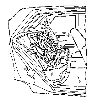
Referring to FIG. 1, the rear passenger
compartment 10 of a vehicle used to transport prisoners
is shown. The compartment includes an exemplary retro-
fitted seat 12 and exemplary belt restraint assembly 14,
which cooperate to support and restrain a seated, rear-
wardly handcu:Efed prisoner frontally, rearwardly, and
laterally.
The exemplary seat 12 is of a single piece,
resin-impregnated silicon fiber sheet mesh construction.
As best seen in FIG. 2 the seat includes a substantially
upright face 16 having a pair of contoured seat backs
16a, 16b formed therein for accommodating two occupants
in the passenger compartment 10. Each contoured seat
back includes a pair of downwardly converging channels
18 in the upright face of the seat back for receiving
and engaging the forearms of a prisoner. The upper
extremities of the channels 18 each include an elbow
recess 19 for receiving the occupant's elbows. Proxi-
mate the converging lower extremities of the channels
-6-
CA 02300724 2000-03-03
18, an intermediates lower recessed portion defines a
pocket 20 for receiving the cuffed hands of the
prisoner. The poc~:et includes a sink 22 which defines
an approximately 1~'4" recess into the pocket. The sink
is filled with a resiliently deformable padding, such as
foam rubber, to present a flush exterior pocket surface.
The padding cushions the hands and wrists of the occu-
pant and provides additional space to accommodate the
handcuffs. p,s may be seen in FIG. 4, in the exemplary
embodiment, t:he lower pocket portion 21 forms the por-
tion of the pocket most deeply recessed in the face of
the seat back:. For example, the lower pocket portion 21
and elbow recesses 19 are approximately equally indented
into the face 16 01the seat back.
The seat back face 16 includes a raised
protuberance 23, bast seen in FIGS. 3 and 4, for
supporting the lower middle back of the occupant. A
substantially triangular upper recessed portion 24 is
located between thc~ diverging upper extremities of the
channels 18 f:or receiving the shoulder blades of the
occupant. Referring particularly to FIG. 4, an upper
lip 26 protrudes horizontally outwardly of the face 16
providing a downwardly counteracting surface for
engaging the shoulc9ers of the occupant and thereby
resisting upward movement.
Rei:urning to FIG. 1, the seat also includes a
rearwardly downwardly sloping seat bottom 44 which
defines a pair of identical laterally concave troughs
44a, 44b each of wlhich is associated with a respective
CA 02300724 2000-03-03
seat back 16a, 16b. The side walls of the troughs pro-
vide lateral ~~ounterforce surfaces which serve to resist
lower body lateral movement. The troughs allow addi-
tional headroom for the occupants. As shown in FIG. 4
the seat back 12a a.nd seat base 12b each define respec-
tive central axes which preferably intersect at a 90°
angle. The rearward, downward slope of the seat bottom
44 serves to urge t:he back of the occupant into engage-
ment with the upright face 16 of the seat back 12a and
resist forward slicling of the lower body of an occupant.
The troughs 44a, 44b are provided with a textured sur-
face to further resist sliding of the lower body of the
occupant.
According to the exemplary embodiment of the
invention, the occupant is frontally supported using an
adjustable seat be_Lt assembly 14 which, when tightened,
urges the prisoner into cooperative engagement with the
contoured seat back 16a, 16b. The seat belt assembly
14, as seen i.n FIGS. 1, 5, 6, 7 and 8, includes a belt
28 having one end :secured to a retractable spool 30.
The spool is attached by a mounting bolt to a standard
plug in an adjacent wing wall of the vehicle. The spool
includes conventional pin lock means for locking the
belt at a desired Length of extension.
25 The unsecured end of the belt is directly
connected to a cinching handle 32 as seen in FIG. 7.
The seat belie assembly 14 also includes a latch 34 which
includes a cinch 36 for engaging and tightening the
belt, a hand:Le engaging tang 38 for detachably engaging
-8-
CA 02300724 2000-03-03
the cinching handle,, and a latching portion 40 for
mating engagement with a buckle 42 secured to the
vehicle. As best shown in FIG. 7, the latching portion
and cinch 40, 36, respectively, of latch 34 are substan-
tially coplanar. Tihe handle-engaging tang 38 is offset
from the plane of t'he latch so as to project outwardly
of the occupant. The handle-engaging tang includes an
aperture 38a :Eor mating engagement with a~resilient
button 39 within a slot 33 in handle 32. The resilient
button may be of fabric such as Velcro'", rubber, or any
other material which will interengage with the aperture
38a to provide some resistance to removal of the cinch-
ing handle from the supporting tang. FIG. 8 shows an
alternative cinching handle 32 molded out of plastic
having an integral arm 35 with a button 39 formed
thereon. The arm i.s resiliently movable so as to enable
the button to engage and disengage from the aperture 38a
in the tang 38. Access to the resilient arm is provided
by a cap 37 which snaps over the well containing the arm.
As seen :in FIGS. 1, 2 and 4 the buckle 42 of
the belt assembly :is supported outwardly of the seat by
a semi-rigid belt lProjection 43 having a flexible
segment proximate the buckle. The end of each belt pro-
jection opposite the buckle is mounted to a bracket 41
which is secured to the vehicle. The buckle 42 may
include a guide for directing the male latching portion
40 of the latch into the female receptacle; of the buckle.
In operation, a rearwardly cuffed prisoner is
seated in the passenger compartment 10 and positioned
-g-
CA 02300724 2000-03-03
for cooperative engagement with one of the seat backs
. 16a, 16b. WhE:n so positioned, the forearms of the
prisoner are received in the downwardly converging chan-
nels 18. The law enforcement officer then grasps the
cinching hand:Le 32, which is attached to latch 34 as
shown in FIGS 1 and 5, with one hand and directs the
latching portion 40 diagonally across the chest of the
occupant toward the buckle 42. The belt 28 is drawn out
of the retractable spool 30 and positioned diagonally
across the chest of the occupant. The latching portion
40 is then inserted into the buckle 42 and retained
therein by operation of the buckle. The cinching handle
32 may then be disengaged from the latch 34 by pulling
the cinching handles away from the buckle 4'2 as shown in
FIG. 7 thereby overcoming and releasing the engagement
between the aperture 38a and the button 39 within slot
33 of the cinching handle. Following this release of
the handle, continued pulling by the officer in the
direction shown draws any residual belt slack through
the cinch portion 36 thereby urging the prisoner into
cooperative engagement with the contoured seat back.
When the belt is fully tightened, the cinching handle 32
may be remounted to the handle receiving~tang 38 of
latch 34. The belt: retains the occupant in cooperative
engagement with the channels 18, pocket 20, upper
recessed portion 24 and upper lip 26, thereby safely and
effectively immobi".Lizing the prisoner for transport. In '
particular, the prisoner is provided with lateral sup-
port by the engagernent of the forearms with channel
-10-
CA 02300724 2000-03-03
walls 18a, 18c when the vehicle negotiates right-hand
turns or chawnel walls 18b, 18d when the vehicle nego-
tiates left-hand turns. The channel walls provide
lateral count~erforce surfaces having a vertical com-
ponent to resist lateral movement of the occupant.
The outward offset of the handle-engaging tang
38 maintains the handle 32 away from the body of the
occupant thereby preventing potentially harmful contact
between the occupant and handle during transport, and
facilitating engagement and removal of the cinching
handle with the tangs.
The seat 12 may also be used as a conventional
seat to transport persons not handcuffed or those hand-
cuffed in front. I:n such applications the protuberance
23, the upper recessed portion 24 and the upper lip 26
comfortably engage the lower back, shoulder blades and
shoulders, respectively, of an occupant.
The term:. and expressions which have been
employed in the foregoing abstract and specification are
used therein as terms of description and not of limita-
tion, and there is no intention in the use of such terms
and expressions of excluding equivalents of the features
shown and described or portions thereof, it being
recognized that the scope of the invention is defined
and limited only by the claims which follow.
-11-