Note: Descriptions are shown in the official language in which they were submitted.
CA 02301130 2000-02-16
WO 98/14339 PCT/HU97/00056
Shackle device for show-shackles mounted periodically on tyres of vehicles
The invention relates to a shackle device for show-shackles mounted
periodically on
tyres of vehicles, which includes a shackle shank and one or more shackle
profile connected
to the shackle shank, having said shackle shank a contact surface borne at
least partly on the
shoe of the tyre while the shackle shank has a cogged part serving for the
connection to the
hub assembly provided with adjusting and fastening mechanism.
During winter periods, a number of solutions aimed at contributing to the
traffic safety
on snow-covered and icy roads became known. One of them consists of the snow-
chain
made from chain-links and provided with flexible fastening elements, that are
mounted on
the driven wheels of vehicles.
The disadvantage of show-chains is that, due to its difficult handling and
fastening, they
are uncomfortable; therefore, other substituting solutions were developed,
i.e. fixed shackle
mechanisms fastened on the tyres in order to promote the clinging to the road
surface.
A mechanism of this kind is described among others in the patent descriptions
US
4.?09.049 and HU '' 10.37'_'.
The common feature of show shackles used at present is, that the part of
shackle in
contact with the tire shoe that promotes the clinging and the cogged shackle
shank
connected to the central hub assembly is formed as a single part made
preferably of bar-
steel, thus ensuring the rigid connection to the hub assembly of the shackle
mechanism.
However, the snow-shackles have the disadvantage that, due to their rigid
structure, the
central hub assembly of the shackle device mounted on the tyre performs an
irregular
roaming motion as a result of the "flattening" of tyre under the load, which
causes a harmful
dynamic stresses during progression. As a result of roaming motion, the
contact between the
shackles and the tyre shoe will be loosened and, with larger and smaller
displacement, will
be re-established on each revolution of the wheel.
CA 02301130 2000-02-16
WO 98/14339 PCT/HU97/00056
-2-
The phenomena described above and the associated dynamic effects have negative
influence on the traveling features of the vehicle and, together with other
disadvantages of
the fixed shackle design, they also endanger the safety in use which, in turn,
is unacceptable
in respect of life- and material safety.
A further disadvantage of the fixed shackle design is that the part of
shackles in contact
with the tyre shoe will be unable to follow the declination of road surface
from the
horizontal plane and its roughness. In extreme cases, this disadvantage of the
rigid shackle
structure may lead to the permanent deformation of shackle shanks, or even,
breaking of the
hub assembly.
The "shackle insertion" described in the patent description HL1 T 55.684 aimed
at
reducing the imperfection found, however, without obtaining complete solution.
The invention is aimed at eliminating the insufficiencies of known structures
provided
with fixed shackle shanks, and developing a show-shackle that enables the
shackle profiles
to follow the deformation of tyre during travel without any harmful effect,
thus ensuring a
more coordinated motion of the shackle profiles with the tyre shoe.
The invention is based on the recognition that, by inserting a particular
sliding
subassembly between the shackle shank and the shackle profiles, the harmful
consequences
due to the flattening of tyre can be avoided by appropriate shortening the
shackle shank
and, as the case may be, by bending the shackle profiles and the shackle shank
relative to
each other, thus enabling the task to be solved.
According to the objective set, the shackle device for show-shackles mounted
periodically on tyres of vehicles according to the invention - which includes
a shackle shank
and one or more shackle profiles connected to the shackle shank, having said
shackle shank
a contact surface borne at least partly on the shoe of the tyre while the
shackle shank has a
CA 02301130 2000-02-16
WO 98/14339 PCT/HiT9'7/00056
-3-
cogged part serving for the connection to the hub assembly provided with
adjusting and
fastening mechanism - is designed in a manner that a sliding subassembly that
allows the
shackle profile to displace towards the hub assembly is inserted between the
shackle shank
and the shackle profile.
A further criterion of the shackle device according to the invention may be
that a spring
bundle is fastened to the sliding subassembly at its outer end facing the
shackle profile, while
the spring bundle is connected either directly or by inserting a connecting
plate to the
shackle profile.
In an exemplary embodiment of the shackle de~lce, the shackle shank has one or
more
guide grooves machined in it and the sliding subassembly includes side plates
in contact with
the side faces of the shackle shank, at least one spacer inserted into the
guide grooves of
shackle shank and allowing a limited displacement, as well as fastening
elements connecting
the side plates with the spacers together.
In another embodiment of the invention, a restoring element e.g. a compression
spring is
arranged in at least one of the guide grooves of the shackle shank, and the
restoring element
is inserted between the shackle shank and the spacer.
In another embodiment of the shackle device, holes of diameter same as the
diameter of
rivets fastening the spring bundle together are at both ends of middle spring
plate in the
spring bundle that is fastened to the sliding subassembly movable on the
shackle shank, and
openings of diameter larger than the diameter of the rivets are arranged at
one end of the
outer spring plates each mounted on both sides of the middle spring plate
within the spring
bundle.
1n a further embodiment of the shackle device according to the invention, the
contact
surface of the shackle profile is completed with a shoe plate of size and form
adapted to the
tyre shoe and the shoe plate is provided with elements improving the clinging
capability.
CA 02301130 2000-02-16
WO 98/14339 PCTIIiU97/00056
-4-
The shoe plate is mounted with grasping ribs suitable to improve the clinging
capability
and the grasping ribs are fastened to the shoe plate parallel to the shackle
profile section
borne on the tyre shoe.
In another design of the shackle deaice, exsections are formed on the shackle
profile
section in contact with the tyre shoe and-or on the grasping ribs mounted on
the shoe plate.
The shoe plate and/or the grasping ribs are fastened by means of cone-head
rivets to the
shackle profile.
The advantage of the shackle dcvrce a~cordm~; to the invention is that, by
using a
structure allowing the shackles to be shortened and bent, the operation of
self adjusting
character of the shackle profiles that adapt rtself to the deformation of the
tyre shoe can be
significantly improved, thus also malnns: the c,p~rational features of the
snow-shackle more
favourable.
In the following, the mvrntron rs described in connection with an exemplary
embodiment, based on drawnngs In the drawings
Fig. 1 shows the front view of the snow-shackle provided with the shackle
device
according to the invention.
Fig. 3 shows the deuce of Fig. I from the direction II
Fig. 3 shows the part-sectional front view of the sliding subassembly
Fig. 4 shows the sectional view along the plane IV-IV of device shown in FiI;.
3
Fig. S shows the sectional view alc,ng the plane V-V of device shown in Fig.
3.
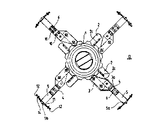
Figs. i and 2 show the snow-shackle design provided with the shackle device
according
to the invention. It is well shown that the flexible shackle device is
composed of the 2
CA 02301130 2000-02-16
WO 98114339 PCT/HIT97/00056
-5-
shackle shank connected to the 1 hub assembly, the 3 sliding subassembly, the
4 spring
bundle, the 5 shackle profile and the 6 connecting plate that connects the 5
shackle profile
to the 4 spring bundle. The spring bundle is fastened by means of the 10
rivets to the 3a
outer end of the 3 sliding subassembly and to the 5 shackle profile. The 2
shackle shank is
connected by means of its end provided with '_'c cogging to the 1 hub
assembly, while the
other end of the '_' shackle shank a connected to the 3 sliding subassembly.
The ?c cogging
enables the position of ? shackle; shank to be modified by displacing it
within the 1 hub
assembly, thereby altering the protruding length of the shackle device, while
the 3 sliding
subassembly allows the distance between the '_' shackle shank and the 5
shackle profile to be
shortened and restored to its original size automatically according to the
deformation of the
tyre.
The Fig. also shows the I 1 shoe plate mounted on the Sa contact surface of
the 5 shackle
profile as well as the 12 grasping ribs fastened to the 11 shoe plate that
serve for improving
the clinging capability. Similarly, the 13 exsections also serving for
improving the clinging
capability are arranged on both the Sb shoe surface of 5 shackle profile and
the 12 grasping
ribs in this embodiment, as shown in Fig. ?.
The clinging capability is also improved by the 14 cone-head rivets that
fasten the 5
shackle profile and the 12 grasping ribs to the 11 shoe plate. It shall be
noted here that the
14 cone-head rivets can also be used in themselves; or even, any other element
improving
the clinging capability by ensuring the better engagement of the 5 shackle
profile with the
snow-covered and icy road surface and the tyre shoe can also be used.
Figs. 3 and 4 shows the arrangement and connection of component parts of 3
sliding
subassembly movable on the 3 shackle shank. 1t is shown that the 31 side
plates in contact
with the 2a side faces of 3 shackle shank and the 7 spacers are fastened
together by means
of the 9 fastening elements, thus forming the covered space in the 3 sliding
subassembly in
which the 2 shackle shank is inserted.
CA 02301130 2000-02-16
WO 98/14339 PCTIHU97/00056
-6-
The ? shackle shank is provided with the ?b guide grooves passing through
between the
2a side faces. In the 2b guide grooves, the 8 restoring elements serving for
resetting the 3
sliding subassembly to its outer end position - compression springs in this
embodiment - are
arranged, on the one hand, and the 7 spacers are also inserted and guided in
the 2b guide
grooves, on the other hand. It is also well shown that, in this embodiment,
the 8 restoring
elements are arranged between the ?b guide groove formed in the 2 shackle
shank and the 7
spacer fastened to the 3 sliding subassembly, thus ensuring the 2 shackle
shank and the 5
shackle profile to be stretched out.
Of course, the 5 shackle profile can be retained in its outer end position by
means of 8
restoring elements arranged in a different manner; thus, the embodiment shown
in the
Figures is only one of the possible solutions without being considered to be
exclusive
Fig. 5 shows the arrangement of the 4 spring bundle composed of the 4a middle
spring
plate and the 4c outer spring plates surrounding it on both sides. It is shown
that the size of
4b holes formed in the 4c outer spring plates - that are forced to slide if
the 4 spring bundle
is bent - at their 4 I c ends connected to the 31 side plates is the same as
the diameter "D" of
the 10 rivets, while the 4c outer spring plates at their 4?c ends fastened to
the 6 connecting
plates are provided with 4d openings of size larger than the diameter "D" of
the 10 rivets, in
order to allow the possibility of sliding.
However, the 4b holes at both ends - 41 a and 4?c - of the 4a middle spring
plate are of
diameter equal to the diameter "D" of the 10 rivets.
The shackle device according to the invention fulfills its function while
performing
complex movement within the snow-shackle fastened to the tyre.
Basically, the rest position of the 3 sliding subassembly, i.e. the maximum
length of the
shackle, is ensured by the reaction exerted by the tyre. The force exerted by
the 8 restoring
elements - also acting towards the end position that determines the maximum
length of the
shackle - is negligible as compared to the reaction exerted by the tyre.
CA 02301130 2000-02-16
WO 98/14339 PCT/AU97/00056
_'7_
During the rotation of the wheel, the tyre rolls over the 5 shackle profiles
borne on the
road surface as well as the 11 shoe plate and its components. When the
flattening tyre rolls
over the 5 shackle profile, the 3 sliding subassembly slides along the 2a side
faces of the 2
shackle to a distance determined by the extent of flattening, while the 1 hub
assembly of the
snow-shackle remains stable essentially at the centre. The method of operation
described
eliminates the unfavourable dynamic impacts and the irregular roaming motion
of the 1 hub
assembly to an unacceptable extent together with its harmful consequences
described above,
that would occur in the case of rigid shackle design.
During the use of the shackle device, the 5 spring bundle enables the 5
shackle profile
borne on the road surface as well as the elements improving the clinging
capability to be
function in a self dependent manner.
The operation of the 4 spring bundle shows hysteresis, as a result of the
friction due to
the compression force of the 10 rivets. As a result of the hysteresis, the 5
shackle profile and
the elements improving the clinging capability while resting on the tyre shoe
"preserve" their
setting according to the lateral angular offset of the road surface and, at
the same time, they
also stand any extreme deviations due to the roughness of the road surface
without damage.
Thus, the use of the -t spring bundle eliminates the risks that occur in the
case of snow-
shackles provided with rigid shackles
The shackle device accordinS to the invention is well suitable to be used
under winter
circumstances in order to improve the traffic safety of various vehicles using
tyres.
CA 02301130 2000-02-16
WO 98/14339 PCT/IiU97/00056
_g_
List of references
1 hub assembly
2 shackle shank '_'a side face
'_'b wide groove
'_'c cogging
3 sliding subassembly3a outer end
31 side plate
4 spring bundle 4a middle spring plate
41 a end
4?a end
4b hole
4c outer spring plates
41 c one end
43c other end
4d opening
shackle profile Sa contact surface
Sb shoe surface
6 connecting plates
7 spacer
8 restoring element
9 fastening elements
rivets "D" diameter
11 shoe plate
12 grasping ribs
13 exsections
14 cone-head rivet