Language selection

Search

Patent 2301355 Summary

Third-party information liability

Some of the information on this Web page has been provided by external sources. The Government of Canada is not responsible for the accuracy, reliability or currency of the information supplied by external sources. Users wishing to rely upon this information should consult directly with the source of the information. Content provided by external sources is not subject to official languages, privacy and accessibility requirements.

Claims and Abstract availability

Any discrepancies in the text and image of the Claims and Abstract are due to differing posting times. Text of the Claims and Abstract are posted:

  • At the time the application is open to public inspection;
  • At the time of issue of the patent (grant).
(12) Patent: (11) CA 2301355
(54) English Title: SCISSORS WORKLIGHT
(54) French Title: LAMPE DE TRAVAIL A DEUX BASES
Status: Expired and beyond the Period of Reversal
Bibliographic Data
(51) International Patent Classification (IPC):
  • F21V 21/30 (2006.01)
(72) Inventors :
  • GROSSMAN, M. GARY (United States of America)
  • QIAN, PEI SHENG (China)
  • SPITLER, BRIAN L. (United States of America)
(73) Owners :
  • REGENT LIGHTING CORPORATION
(71) Applicants :
  • REGENT LIGHTING CORPORATION (United States of America)
(74) Agent: FINLAYSON & SINGLEHURST
(74) Associate agent:
(45) Issued: 2004-11-02
(22) Filed Date: 2000-03-20
(41) Open to Public Inspection: 2000-11-26
Examination requested: 2000-05-19
Availability of licence: N/A
Dedicated to the Public: N/A
(25) Language of filing: English

Patent Cooperation Treaty (PCT): No

(30) Application Priority Data:
Application No. Country/Territory Date
09/320,259 (United States of America) 1999-05-26

Abstracts

English Abstract


A portable worklight having at least two base sections that
are operable between open and closed positions. The base sections
are pivotally connected and when in a closed position, the base
sections nest together. When in an open position, the base
sections support said worklight in an upright position by
providing opposingly located support sections.


Claims

Note: Claims are shown in the official language in which they were submitted.

The embodiments of the invention in which an exclusive property
or privilege is claimed are defined as follows:
1. A portable worklight operable between open and closed
positions comprising:
a light housing comprising a light source;
an outer base section and an inner base section;
said outer base section has four legs which form a
frame and said inner base section comprising two opposingly
located legs located in between said legs of said outer base
section;
said light housing attached to said legs of said inner
base section;
said legs of said base sections pivotally connected;
in said closed position, said base sections nest
together with said frame formed by said outer base section
surrounding said light housing and said inner base section; and
in said open position, said base sections support said
light housing in an upright position.
2. The apparatus of claim 1 wherein said inner base
section includes a third leg which results in the formation of
a three-sided frame.
3. The apparatus of claim 1 wherein said outer legs are
longer in length than said inner legs.
7

Description

Note: Descriptions are shown in the official language in which they were submitted.


CA 02301355 2003-12-08
SCISSORS WORKLIGHT
Background of the Invention
The invention relates to a portable worklight and more
specifically, a portable worklight that uses a foldable stand
that collapses inwardly to.produce.a slim-profile light that is
compact for storage purposes.
Summary of the Invention
In the field of portable worklights there is a competing
design consideration between the need for a sturdy base to
support the worklight and the need to provide a compact design
for ease of storage. A sturdy base with a wide foot print is
desirable so that the light is placed in the most stable
position possible. On the other hand, the wider the foot print
of the base, the more space is required to store the worklight.
The present invention provides a solution to both competing
design considerations. It provides two frames that are
pivotally connected and extend between open and closed
positions. In an open position, the frames provide a base which
supports the worklight. In a closed position, the frames nest
together to reduce the space needed to store the device.
Consequently, the present invention seeks to provide a
worklight with foldable frames or base sections that act as a
base when in an open position and which nest together when in a
closed position for ease of storage.
More particularly the invention in one broad aspect
provides a portable worklight operable between open and closed
2

CA 02301355 2003-12-08
positions comprising a light housing comprising a light source,
an outer base section and an inner base section, the outer base
section having four legs which form a frame and the inner base
section comprising two opposingly located legs located in
between the legs of the outer base section. The light housing
is attached to the legs of the inner base section and the legs
of the base sections are pivotally connected. In the closed
position, the base sections nest together with the frame formed
by the outer base section surrounding the light housing and the
inner base section and in the open position, the base sections
support the light housing in an upright position.
Brief Description of the Drawings
The novel features which are characteristic of the present
invention are set forth in the appended claims. However, the
invention's preferred embodiment, together with further objects
and attendant advantages, will be best understood by reference
to the following detailed description taken in connection with
the accompanying drawings in which:
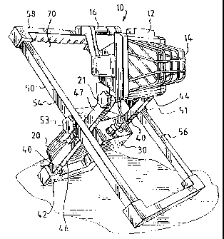
Figure 1 is a front perspective view of one embodiment of
the present invention.
Figure 2 is a side view of the embodiment shown in Figure
1.
Figure 3 is a rear perspective view of the embodiment shown
in Figure 1.
Figure 4 is a partial front view taken along line 4 - 4.
3

CA 02301355 2000-03-20
ATTORNEY
DOCKET NO. 2587
Detailed Descriy~tion Of The Preferred Embodiment
Set forth below is a description of what is currently
believed to be the preferred embodiment or best example of the
invention claimed. Future and present alternatives and
modifications to the preferred embodiment are contemplated. Any
alternates or modifications in which insubstantial changes in
function, in purpose, in structure or in result are intended to
be covered by the claims of this patent.
As shown in Figure 1, the worklight 10 of the present
invention includes a light housing 12 which contains a lamp (not
shown), grill 14, and handle 16 and the other components needed
to create a working light. Light housing 12 is pivotally
connected to first frame or base section 40 by fasteners 21 and
23. As shown in Figures 1 and 3, a switch 30 is connected to
light housing 12 and electrical receptacle 32 for the electrical
operation of the lamp. Receptacle 32 may also include external
outlets 34 and 36 which may be used to energize other electrical
devices. An extension cord 20 may also be provided to energize
the light and outlets 34 and 36 and which may stored on holder
71. First frame or base section 40 is pivotally connected to
second frame or base section 50 by fasteners 51 and 53.
As shown, the frames may be rectangular or square-like in
configuration or in other shapes which may nest together. Frame
40 has a base portion 42, opposing sides 44 and 46 and free ends
4

' Mill I
CA 02301355 2000-03-20
ATTORNEY
DOCKLT NO. 2587
47 and 48 to which light housing 12 is pivotally connected.
Frame 50 is similarly constructed with a base 52, opposing sides
54 and 56 and top 58. The overall length and width of first
frame 40 with attached light housing 12 is sized to fit within
second frame 50. Configuring the frames in this manner permits
the frames to pivot, scissor-like, about fasteners 51 and 53
between open and closed positions.
In an open position, bases 42 and 52 are opposing located
and form a support upon which the worklight rests in an upright
position. In a closed position, the frames or base sections nest
together as shown in Figures 2 and 4. This reduces the foot
print of the base as well as the total space occupied by the
worklight. This, in turn, makes it easier to store the light.
In use, the frames or base sections are moved from a closed
position as shown in Figure 2 to an open position as shown in
Figure 1. Extension cord 20 is then connected to an outlet which
energizes receptacle 32 which, in turn, and in combination with
switch 30, operates to energize the lamp. To return the device
to storage, the frames or base sections are directed inwardly
until nested. The device then may be hung on a support surface
by inserting a hook or a similar object through opening 70 which
is located between top 58 and light housing 12.

i lilt
CA 02301355 2000-03-20
ATTORNEY
DOCKET NO. 2587
It should be understood that various changes and
modifications to the preferred embodiment described would be
apparent to those skilled in the art. Changes and modifications
can be made without departing from the spirit and scope of the
present invention and without diminishing its intended
advantages. It is, therefore, intended that such changes and
modifications be covered by the following claims.
6

Representative Drawing
A single figure which represents the drawing illustrating the invention.
Administrative Status

2024-08-01:As part of the Next Generation Patents (NGP) transition, the Canadian Patents Database (CPD) now contains a more detailed Event History, which replicates the Event Log of our new back-office solution.

Please note that "Inactive:" events refers to events no longer in use in our new back-office solution.

For a clearer understanding of the status of the application/patent presented on this page, the site Disclaimer , as well as the definitions for Patent , Event History , Maintenance Fee  and Payment History  should be consulted.

Event History

Description Date
Time Limit for Reversal Expired 2008-03-20
Letter Sent 2007-03-20
Grant by Issuance 2004-11-02
Inactive: Cover page published 2004-11-01
Inactive: Final fee received 2004-08-17
Pre-grant 2004-08-17
Notice of Allowance is Issued 2004-02-18
Letter Sent 2004-02-18
Notice of Allowance is Issued 2004-02-18
Inactive: Approved for allowance (AFA) 2004-01-27
Amendment Received - Voluntary Amendment 2003-12-08
Inactive: S.30(2) Rules - Examiner requisition 2003-06-09
Application Published (Open to Public Inspection) 2000-11-26
Inactive: Cover page published 2000-11-26
Letter Sent 2000-06-08
Inactive: First IPC assigned 2000-05-29
Request for Examination Received 2000-05-19
Request for Examination Requirements Determined Compliant 2000-05-19
All Requirements for Examination Determined Compliant 2000-05-19
Inactive: Filing certificate - No RFE (English) 2000-04-06
Filing Requirements Determined Compliant 2000-04-06
Letter Sent 2000-04-06
Application Received - Regular National 2000-04-05

Abandonment History

There is no abandonment history.

Maintenance Fee

The last payment was received on 2003-12-18

Note : If the full payment has not been received on or before the date indicated, a further fee may be required which may be one of the following

  • the reinstatement fee;
  • the late payment fee; or
  • additional fee to reverse deemed expiry.

Please refer to the CIPO Patent Fees web page to see all current fee amounts.

Fee History

Fee Type Anniversary Year Due Date Paid Date
Registration of a document 2000-03-20
Application fee - standard 2000-03-20
Request for examination - standard 2000-05-19
MF (application, 2nd anniv.) - standard 02 2002-03-20 2001-12-20
MF (application, 3rd anniv.) - standard 03 2003-03-20 2002-12-18
MF (application, 4th anniv.) - standard 04 2004-03-22 2003-12-18
Final fee - standard 2004-08-17
MF (patent, 5th anniv.) - standard 2005-03-21 2004-12-20
MF (patent, 6th anniv.) - standard 2006-03-20 2006-02-06
Owners on Record

Note: Records showing the ownership history in alphabetical order.

Current Owners on Record
REGENT LIGHTING CORPORATION
Past Owners on Record
BRIAN L. SPITLER
M. GARY GROSSMAN
PEI SHENG QIAN
Past Owners that do not appear in the "Owners on Record" listing will appear in other documentation within the application.
Documents

To view selected files, please enter reCAPTCHA code :


To view images, click a link in the Document Description column. To download the documents, select one or more checkboxes in the first column and then click the "Download Selected in PDF format (Zip Archive)" or the "Download Selected as Single PDF" button.

List of published and non-published patent-specific documents on the CPD .

If you have any difficulty accessing content, you can call the Client Service Centre at 1-866-997-1936 or send them an e-mail at CIPO Client Service Centre.


Document
Description 
Date
(yyyy-mm-dd) 
Number of pages   Size of Image (KB) 
Representative drawing 2000-11-17 1 12
Claims 2003-12-08 1 28
Description 2003-12-08 5 162
Drawings 2003-12-08 1 46
Description 2000-03-20 5 154
Drawings 2000-03-20 1 50
Claims 2000-03-20 1 33
Abstract 2000-03-20 1 13
Cover Page 2000-11-17 1 32
Representative drawing 2004-10-04 1 21
Cover Page 2004-10-04 1 45
Courtesy - Certificate of registration (related document(s)) 2000-04-06 1 113
Filing Certificate (English) 2000-04-06 1 163
Acknowledgement of Request for Examination 2000-06-08 1 177
Reminder of maintenance fee due 2001-11-21 1 112
Commissioner's Notice - Application Found Allowable 2004-02-18 1 161
Maintenance Fee Notice 2007-05-01 1 172
Correspondence 2004-08-17 1 29