Note: Descriptions are shown in the official language in which they were submitted.
CA 02302553 2000-03-O1
WO 99112116 PGT/US98/18269
SYSTEM AND METHOD FOR REMOTE
TRANSACTIONS BETWEEN A CUSTOMER AND VENDORS
DESCRIPTION
Technical Field
The invention relates to facilitating commerce through the use of modern
communications.
Related Application
This application is a continuation-in-part of prior copending application S.N.
GO/057,499 filed September 4, 1997.
Background of Invention
Many commercial transactions fall into the category of retailing.
Historically, retailing in this country began with single stores in single
locations.
Improvements resulted in a single branded store in multiple locations, i. e.
chain
stores. Evolution brought "shopping malls", i.e. multiple stores in single
locations.
Here emphasis is placed on variety and chuices at a convenient location. This
led
to the c.~ncept of a "store within a store" - in order to provide quality
brand names
and to increase retail traffic, many of the large retailers experimented with
the
concept of renting space to other retailers. In addition, another advance was
the
"discount warehouse". Here, stores focused on variety and "every day low
prices",
discounted prices due to large volume purchases. in the larger discount
warehouses, the retailer has often requested the manufacturer to manage its
own
inventory instead of the retailer buying and managing the risk of this
inventory. To
CA 02302553 2000-03-O1
WO 99/12116 PCT/US98118269
2
permit such inventory management, the manufacturer's computer system is
networked to the retailer's computer system. The discount warehouse led to the
specialized discount warehouse. Parallel to these developments came the advent
of
direct catalog marketeers which sell a variety of products and services
directly to
end users through catalogs. In the early 1990's TV shopping networks on cable
channels appeared. .Finally companies have offered on-line shopping malls. In
parallel with these changes, direct-to-home retailing has become a necessity
in
several industries because of competition and the requirement for lower costs
of
distribution and higher margins. In the personal computer industry, for
example,
several companies have been very successful with direct-to-home retailing. In
other
industries, the same type of transaction is gaining ground, particularly books
and
compact discs.
Aside from price and competition driving these changes, it should also be
recognized that consumers are getting older and have many more demands on
their
time. In particular, members of the large segment of dual income households
value
their time more than do other segments and thus these consumers both have less
time to shop and are less willing to spend time on shopping. These consumers
prefer not to go to shopping malls but to do their shopping, especially for
repetitive
purchases and other mundane shopping, in the comfort of their homes. This does
not mean that these consumers will never go to a mall. Shopping for frequently-
used non-perishable goods and services will be done using catalogs while fun
shopping or entertainment shopping for special gifts and one-of a-kind
articles will
continue to be done in shopping malls.
In addition, changes in telecommunications led to experiments using the
Internet and other networking technologies. Initially, business transferred
some
administrative functions to the new communications but once experience showed
the
value of this new technology, entities started to use the new technologies for
CA 02302553 2000-03-O1
WO 99/12116 ~ PGT/US98/18269
3
mission critical applications such as management of 401K portfolios, taking
orders
from customers, providing orders to suppliers and interactive customer support
programs. Many companies have experimented with the idea of offering shopping
malls on the Web for consumers and businesses. However, on-line shopping malls
for consumers have been successful only in niche markets and with significant
limitations with respect to significant expansion. Indeed, brand name
companies
have closed on-line shopping malls for lack of traffic.
It is apparent by noting that sales from catalogs have become the highest
growth segment within the retailing business while shopping mall sales are
declining, that there is a need for a new transaction system. It is also of
note that
the Internet has increasingly become reliable in commercial applications
although
shopping on the Internet still requires a complex assortment of equipment and
software (typically a personal computer, a high speed modem, a telephone line,
a
browser and some electronic payment software). These systems are expensive,
their
use is time-consuming and a fairly high level of computer literacy is
required, all of
which are not commonly available. In addition, it is not intuitive for a
member of
an average household to get on-line with a personal computer to order goods
and
services. It is more intuitive for a household member to check advertising
sections
of local newspapers, and browse catalogs, as opposed to accessing the Web page
of
a local grocery store or mail order company. In short, many more consumers are
"reading" savvy than "computer" savvy. They continue to make shopping
decisions
from reading or browsing local and/or national newspapers, Yellow Pages,
catalogs,
magazines and the like. While a variety of standards are discussed for
Internet and
other telecommunications applications and particular electronic transactions,
there is
still much confusion in the marketplace especially when end users are
involved,
between the diverse requirements of credit card companies, banks, merchants,
software companies and regulatory agencies.
CA 02302553 2000-03-O1
WO 99/12116 PGT/US98/18269
4
While the foregoing has related to retailing, many of the same problems are
exhibited at other levels of the chain of commerce. The invention therefore
has
applicability at all levels of commerce, where one party has the objective of
selling
goods or services and another party has the objective of buying goods or
services.
All of the foregoing makes it apparent that there is a need for application of
the new technologies, but the particular way in which these new technologies
should
be applied has not surfaced.
Summary of Invention
In order to overcome the foregoing problems and difficulties, the invention
provides a system and method to collect the combined transaction information
which
may be needed to complete a transaction, and do so in an intuitive way and non-
intrusive way. In particular, the invention enables use to be made of pre-
existing
data, i.e. printed (or the like) data appearing in advertisements, catalogs,
etc. In
other words the user has, in effect, a library or catalog which defines or
identifies
many potential subjects of commerce. The library or catalog (such as
advertisements in a magazine, newspaper or the like) is pre-existing in the
sense
that it is created prior to the use by the user. The user merely selects some
portion
of this pre-existing data to initiate a transaction by defining its subject.
More particularly, in respect of one aspect, the invention allows a user to
apply a simple-to-use data capture unit to pre-existing data to capture that
data.
Typically, the captured data may relate to some desired goods or services -
the data
however, since it does not identify the purchaser, is inadequate to completely
define
a transaction. When the user has captured the desired data, the data capture
unit
can be joined or coupled to any one of a number of available interfaces to
link the
captured data to an intermediary or facilitator. The intermediary or
facilitator stores
CA 02302553 2000-03-O1
WO 99/12116 PCT/US98/18Z69
additional data which is necessary to define a transaction. The interface
provides a
data forwarding function or network access function linking the data capture
unit to
the facilitator or intermediary. The facilitator or intermediary then may
accept the
captured data and adds to it additional pertinent data to provide the data
necessary
5 to complete a transaction. The facilitator or intermediary may then forward
the
combined data to a fulfilling entity to complete the transaction.
Thus, in respect of one aspect, the invention provides a system to provide
combined transaction information from a user and a facilitator comprising:
portable data capture means to capture user-selected data defining a
particular transaction,
data forwarding means responsive to the data capture means for acquiring
data from the data capture means and for forwarding the acquired data, and
facilitator means responsive to the forwarded data for associating pre-stored
data with the forwarded data to create the combined transaction information.
The system may also include a ftllfiller andlor intermediary which responds
to the combined data in order to complete the transaction.
The invention allows the capture of orders at the point of intent and
transparently route the orders to participating merchants. A system according
to one
embodiment of the invention comprises a data capture unit which may be in the
form of a pen that is used to scan coded information (e.g., bar codes) in any
print
medium. This data capture unit, in conjunction with a data forwarding or
docking
unit, automatically dials up and delivers purchase requests to a facilitator
or remote
transaction center through a suitable communication resource. Software at the
CA 02302553 2000-03-O1
WO 99/12116 PCT/US98/18269
6
facilitator matches the requests with a customer profile, such as credit card
number,
home address, etc. The facilitator can then send the purchase requests to the
merchant's location (or agent) using standard dialup or dedicated circuits,
satellite
communications or the Internet. While the communications can use any desired
format, there are advantages which flow from using Internet Protocol (IP) for
the
transmission from the data forwarding unit to the facilitator. For one thing,
if IP
format is used, then' the facilitator may simply retransmit in the same format
over
the Internet. Merchants process the orders and deliver goods or services
directly to
the user/consumer. In addition to purchase requests, the invention can be
adapted to
process request for information, or a request for call back, implement bill
paying as
well as other peripheral and supplemental transactions as will be described.
Users
are able to carry the data capture unit anywhere, anytime around the world.
Data forwarding units or docking stations can be made available in public
places such as hotel rooms, airline clubs, libraries etc. In addition, as will
be
described, while the data capture unit is personalized, the data forwarding
unit or
docking station is not. As a result a data forwarding unit can be used by any
data
capture unit without adverse impact on the transaction.
A unique identity number is stored inside the data capture unit. Sensitive
and confidential information such as the user's credit card number is stored
in a
secure server at the facilitator. The system facilitates transactions between
the user
and merchants/vendors. For the user, there is no need to get up, pick up the
phone
to call a toll free number, give out the credit card information every time,
or talk to
a sales person. Also, there is no need to incur the significant cost of
personal
computer ownership, learn computer systems or waste time browsing the web.
Benefits also extend to vendors. Vendors are able to capture the consumer at
the
"point of intent" versus waiting for the sale at the "point of sale".
Therefore for the
vendors the system according to the invention complements available
distribution
CA 02302553 2000-03-O1
WO 99/12116 PCT/US98I18269
7
channels and enhances the power of advertising. In addition, costs related to
setting
up and managing call centers are reduced, and errors in processing orders are
eliminated. Furthermore, by tracing which advertising medium generated the
captured data, vendors are able to clearly determine the effectiveness of an
advertisement, enabling them to optimize their merchandising expenditures.
In respect of one particular aspect of the invention, the data capture means
may comprise a bar code scanner with which a user can capture bar code
information appearing in a catalog, advertisement, magazine or the like. The
bar
code scanner, in addition to storing the scanned or captured data, also stores
identification information, i.e. an electronic serial number (ESN). It is an
advantage that the scanner is portable. In order to communicate the captured
data
to the intermediary or facilitator, a data forwarding means/docking station or
network access unit is used. The data capture ulut is coupled to the docking
station
to transfer the stored data over an existing communications system such as the
telephone network, to a facilitator in the form of a remote processing system.
The
remote processing system is addressed by the data forwarding unit and accepts
the
data forwarded thereto. This data in part, particularly the identification
information, is useful as a pointer to identify additional data which can be
combined
with the user-captured data. The intermediary or facilitator may also validate
the
transferred data, particularly based on the identification information. Having
been
processed (validated and combined), the combined data can then be forwarded
over
another communications system such as the Worldwide Web to a fulfillment
entity
or a selected fulfillment entity in order to complete the transaction.
Thus, in respect of the system aspect of the invention, useful functions are
performed by a data capture unit, a data forwarding unit, a facilitator and
fulfiller
or merchant.
CA 02302553 2000-03-O1
WO 99/12116 PCT/US98I18269
8
The data capture unit is used by a user to capture data partially defining a
transaction after that data is selected by the user. In a purchase
transaction, the user
may select data defining the subject of a purchase. In one embodiment the data
capture unit is a pen like bar code scanner which can be used to read and
record bar
codes appearing in some medium, such as a print medium, reviewed by the user.
In
other embodiments the bar code scanner may take on forms other than the form
of a
pen. In still other embodiments the captured data may be in a medium other
than a
print medium, such as television, either cable or broadcast. In other
embodiments
the data may be in formats other than bar coded.
The data forwarding unit or docking station is responsible for responding to
the presence of a data capture unit, when docked, to initiate a communication
session over a communication link, with the facilitator or remote processing
center.
The purpose of the session is to transfer data from the data capture unit to
the
facilitator. To perform this function the data forwarding unit may include a
dial up
modem programmed to connect over the PSTN either with the facilitator or a
node
of a network through which the facilitator can be reached. The node may be a
resource of an Internet Service Provider (ISP) and the network used to reach
the
facilitator may be the Internet or other similar network. The modem rnay be
wired
or wireless.
The facilitator is required for several functions. In the first place, in one
embodiment and in the case of a purchase transaction, the captured data
defines the
subject of the proposed transaction but not the purchaser. Rather the
transmitted
data may, in addition, define or identify the data capture unit. Thus one
function of
the facilitator is to use the identification of the data capture unit to
access additional
data identifying the user and necessary to the transaction. Another function
of the
facilitator is to authenticate or verify that the data capture unit identified
in the
transmitted data is an authorized unit, that it has been assigned for use and
has not
CA 02302553 2000-03-O1
WO 99/12116 PCT/IJS98/18269
9
been reported as missing or stolen. The facilitator will then combine the
captured
data and the additional data so that the transaction is more completely
defined. In
the event that the facilitator does not also perform the function of
fulfilling the
proposed transaction, the facilitator, from the captured data, identifies the
entity
who will fulfill the transaction, and the transaction data is transmitted
thereto.
The communication from the facilitator to the fulfilling party may embody a
secure or encrypted transmission over a suitable communication resource such
as
the Internet.
The falling party is responsible for accepting the transaction data and then
fulfilling the transaction; in the case of a purchase request, this involves
forwarding
to the identified user the subject of the transaction.
Supplemental or ancillary to the completion of the transaction is the
framework by which the parts of the system are put into place and initialized.
In
other words, data capture units have to be distributed and accompanying that
process, the user profiles must be registered to create the facilitator's data
base.
Additionally, in order for the data capture units to function as intended,
steps need
to be taken to create and distribute the media carrying the data for capture.
To
accomplish this merchants must register the goods/services to be offered,
codes
need to be assigned and the media carrying the appropriate codes must be
created
and distributed.
Aside from applicability to purchase requests, the invention can also be used
to facilitate requests for bill paying, information, merchandise return,
polling and
coupon management. In addition, the invention allows capture of vastly more
effective peripheral information. By adding the ability to capture the time of
the
user scanning of a code and transmitting that piece of data along with the
other
CA 02302553 2000-03-O1
WO 99/12116 PCT/US98118269
transaction information, the facilitator or the merchant can now determine,
for each
transaction mediated by the invention, at just what time of day the user
initiated the
transaction. Likewise, by adding advertisement (or media) identification to
the
scannable code, the merchant (or facilitator) can now correlate transactions
with the
5 advertisement or media responsible for the transaction.
Brief Description of the Drawings
The present invention will now be further described in the following portions
of this specification when taken in conjunction with the attached drawings in
which
like reference characters identify identical apparatus and in which:
10 Fig. 1 is an overall block diagram identifying significant components of
the
invention;
Fig. 2 is a flow chart of various steps which are implemented in accordance
with an aspect of the invention;
Fig. 3 is a side view and block diagram of the data capture unit, one element
of the system of the present invention;
Fig. 4 is a block diagram of a data forwarding unit or docking station which
is another element of the system of the present invention;
Fig. 5 schematically illustrates a stream of data which may emanate from a
data capture unit and be transmitted to a facilitator~or remote transaction
center; and
Fig. 6 is a more detailed block diagram of a preferred embodiment of the
facilitator or remote processing center.
CA 02302553 2000-03-O1
WO 99/12116 PCT/US98I18269
11
Detailed Description of Preferred Embodiments
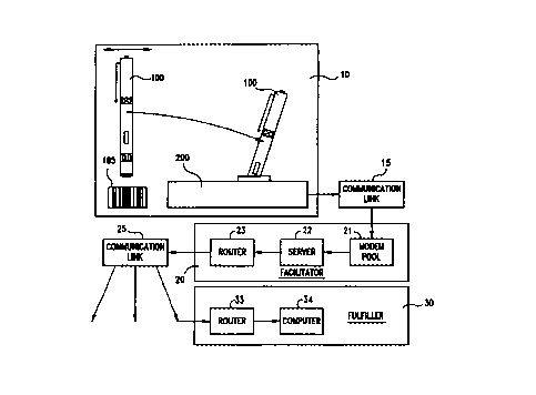
Fig. 1 graphically illustrates the typical components of a system in
accordance with the invention. As shown in Fig. 1, there are three main
centers of
activity, a user region 10, an intermediary region 20 which is occupied by the
facilitator arid a region 30 which is occupied by the fulfiller. The
transaction which
is the subject of the activity of the apparatus of Fig. 1 is initiated by a
user. One
type of transaction is a purchase transaction and it is initiated by the user
capturing
data identifying the goods or services to be purchased. One example of a data
capture device is the bar code scanning pen 100. As will be described, the bar
code
scanning pen 100 is' portable and can be applied to capture pre-existing data
in the
form of a bar code such as exemplary bar code 105. For example printed
catalogs,
newspaper advertisements and the like may be augmented to include bar coded
data
identifying offered goods and/or services. It will be appreciated that the
offered
goods and/or services must be uniquely identified in the bar coded data but
that
unique identification, depending on the context may require more or less data.
If the
system is used by only one vendor, less data is required for a particular item
than if
the system is used by 10 vendors, 100 vendors, etc.
At this point, it is also useful to refer to the flow chart of Fig. 2. As
shown
in Fig. 2, the actions of the user and facilitator are represented in six
steps. In step
S1, the user applies the data capture unit to some pre-existing data to
capture that
data. The captured data must identify the desired goods or services. The data
capture device is not limited to capturing data about a single transaction and
thus
step S2 allows the data capture operation to be repeated with other pre-
existing data
at the user's discretion. Assuming that step S1 is repeated a sufficient
number of
times to satisfy the user's desire, the next step S3 is to join or couple the
data
capture unit to a selected interface. In particular, data captured by the user
must be
manifested to an entity which can act on the transaction request. That entity
CA 02302553 2000-03-O1
WO 99112116 PCT/US98/18269
12
requires data in addition to that captured by the user. Typically the
additional data
will include information about the user such as name, address, bank account
andlor
credit card information and the like. As will be described, this information
is not
contained in a data capture unit and thus will be obtained elsewhere. In
addition to
the ability of the data capture unit to capture pre-existing data, the data
capture unit
100 also includes the ability to transfer that information to a selected
interface such
as the data forwarding element or network access device or docking station
200.
Fig. 1 shows a typical data capture unit 100 docked in a docking station 200.
The
interface between the data capture unit 100 and the docking station 200 may
use any
conventional technology. For example that interface may be optical or
electrical.
The docking station 200 is connected via a communication link 15 to the
facilitator
20. The communication link 15 at the docking station 200 can transmit
information
derived from the data capture unit 100 to the facilitator 20. The
communication
link 15 may be the public switched telephone network or the like. If desired,
the
link 15 may be an IP connection via the PSTN. As shown at step S4, the
interface
establishes a link to the facilitator 20 which link is used to communicate the
captured data. At step S5, the facilitator processes the data. Typically, at
least two
functions are performed; the first is verifying the authenticity of the data
and the
second is accessing additional data to combine with the transmitted data. In
one
example, the data capture unit 100 will store identity information which
identifies
the particular data capture unit 100. This identity information is transmitted
to the
facilitator 20 along with the captured data and is used at the facilitator in
an
authenticity or verification step. The same identity information, after the
authenticity or verification step is satisfied, can be used to access the
additional
information which will be combined with the captured data. Once the additional
data is accessed and combined with the captured data, the combined information
is
transmitted to the fulfiller entity in step S6. As seen in Fig. 1, this
process occurs
over the communication link 25. Communication link 25 may be the same as or
different from the communication link 15 and may for example include the
CA 02302553 2000-03-O1
WO 99/12116 PCT/US98/18269
13
Worldwide Web, or secure Internet connections with end-to-end encryption. The
fulfiller entity 30 accepts the combined information and then executes the
transaction which is defined by that information.
Fig. 3 is a side view of the data capture unit 100 and a block diagram of its
components.
Referring first to the side view of the data capture unit 100, Fig. 3 shows
that it is in pen form having a body 190 and a clip 191. Outwardly data
capture
unit 100 includes interfaces comprising electrical contacts 160 and a bar code
scanner 110, status revealing LEDs 123 and an on-off switch 181. Also shown in
Fig. 3 is a power source comprising batteries 180, memory including read only
memory 170 and buffer memory 140, a microprocessor 120, a scan cancellation
button 150 and a real time clock 145.
The real time clock 145 is, in reality, merely a counter, however a counter
with sufficient capacity, given reasonable resolution, to count for a time
approaching the lifetime of the batteries 180 or much longer than the expected
period between instances in which the data capture unit interacts with the
facilitator
20. The counter in clock 145 will of course begin counting as soon as it is
powered. Each time data is stored in the buffer RAM 140, the data will come in
part from the data scanner 110 and also in part from the count in the clock
145.
The first time that this particular data capture unit interacts with the
facilitator 20, it
will transmit its ESN, the stored data (which includes the count in the clock
145 at
the time of scanning) as well as the count in the clock 145 at the time of
data
transmission. Because the counter in clock 145 counts at a constant rate. data
processing at the facilitator 20 enables any given count to be translated to
time of
scanning, where time of scanning implies not only time of day but day of the
month
and year as well.
CA 02302553 2000-03-O1
WO 99!12116 PCTIUS98118269
14
As illustrated in Fig. 3, the data capture unit 100 can collect data from
different pre-existing sources such as bar coded data found in various forms
of print
media or the like. As is conventional, the scanner includes a light source
such as
an LED for generating light, a lens for focusing this light on the printed
material
and for collected reflected light and covers for shielding the device from
dust and
humidity, a photoreceptor for reading the reflected light and an analog to
digital
converter and associated electronics. In use, the operator holds the data
capture
unit 100 like a pen and sweeps the tip of the unit across bar coded data. The
variations in reflected light intensity are converted to an electric signal by
the
photoreceptors; this scanned data is converted from analog to digital form and
input
to the microprocessor 120 (or another form of computer such as a custom logic
array) to identify whether the scan belongs to a standard set of scan formats
and to
generate an indication of whether a successful scan has been achieved. This
indication may be visible (generated by the illumination of one of several
LEDs
123) or audible (generated by an internal speaker). A signal indicating a bad
scan
could also be generated and indicated by illuminating another LED or using a
different audible tone or the like. In other embodiments, the absence of a
signal for
a successful scan is taken as an indication of an unsuccessful scan. The
microprocessor 120 executes algorithms to enhance the detection of the bar
code
indicia as is also well known. On successful processing, the data obtained in
the
scan is stored in the buffer RAM 140 which can comprise flash RAM chips or
other
types of RAM. The microprocessor 120 keeps an account of the level of
utilization
of the memory 140 and provides signals to the user when the memory is full or
approaching full. If desired, the microprocessor 120 can also allow the user
to edit
or control the data in memory using the scan cancellation button 150 to
selectively
delete scanned data. Each depression of the cancellation button is effective
to delete
the data corresponding to a single transaction, i.e., scan data plus the
corresponding
clock data. The captured data, at a minimum, identifies the subject of a
purchase
desired by the user. Depending on the context, the requirements for this
CA 02302553 2000-03-O1
WO 99/12116 PCT/US98/18269
identification will require more or less information. For example, if the data
may be
captured from a wide variety of sources of pre-existing data, the information
required to identify and distinguish one item from all other potential
purchases in
this universe may be extensive. On the other hand, the data may be scanned
from a
5 single publication of controlled content so that only a few bits are
required to
uniquely identify the subject. Regardless of context, it is necessary that the
captured
data identifies the subject of the desired transaction.
Other embodiments of the invention can capture data from different data
formats such as magnetic ink, radio frequency transmissions such as FM radio
and
10 television broadcasts. The real time clock 145 allows the time of scanning
to be
captured along with the scanned data.
In order to make the scanned data useful, it must be transmitted to the
facilitator 20 for data processing. To this end, the invention also includes a
data
forwarding unit or network access device such as the docking unit 200. The two
15 important components of the docking unit 200 are first an interface to
accept data
from the data capture unit 100 and another interface to transmit that data to
the
facilitator 20. As will be described, while the particular data capture unit
100 used
by a particular individual may be unique, the data forwarding unit which is
used can
be any available data forwarding unit.
The housing 290 of the Data forwarding Unit 200 is of suitable shape and
size for stable and unobtrusive placement on a flat surface, and attractive to
view,
e.g., in the shape of a pyramid. The housing has suitable ports 235 for
connections
required by the communication functions. This can implement network
connections
via the dial up network either directly or via an Internet Service Provider.
The
docking slots 220 is provided with features that aid the mating process, and
ensure
that the data capture unit is naturally placed in a manner designed to ensure
proper
CA 02302553 2000-03-O1
WO 99/12116 PCT/US98118269
16
contact with the data port 160, and effective to transfer data. Feedback to
the user
regarding the status of the transfer of data from the Data Capture Unit 100 to
the
Data forwarding Unit 200, and from the Data forwarding Unit 200 to the
Facilitator
20 is provided by LEDs 250. Feedback to the user can also be provided by an
alphanumeric display 260 placed on the surface of the housing 290 capable of
displaying several characters and pictures. Optionally, the alphanumeric
display
could also function as a display for displaying information obtained from the
Facilitator.
Electrical power is provided to the Data forwarding Unit 200 by a battery,
solar cells, telephone company lines, or a power supply 240 connected to a
standard
wall outlet.
The main components of the data forwarding unit 200 are a first interface
with the data capture unit 100, the function of which is to acquire data from
the
data capture unit 100, and a second interface with a communication link to
transfer
the data received from the data capture unit 100 to the facilitator 20. As
will be
described, the interface between the data forwarding unit 200 and the data
capture
unit 100 can employ any conventional technology; two which are convenient are
electrical and/or optical interfaces. Preferably the communication link is via
the
Internet andlor the public switched telephone network and the data forwarding
unit
200 can be electrically connected thereto. Those skilled in the art will
understand,
however, that it is also possible to use a wireless link between the data
forwarding
unit 200 and portions of the public switched telephone network.
Fig. 4 is a block diagram of vne embodiment of a data forwarding unit 200.
In one embodiment, the housing of the data forwarding unit 200 or docking base
unit comprises one or more electrical connectors 220 to which mating
connectors
120 on the data capture unit 100 can be connected or docked. This electrical
CA 02302553 2000-03-O1
WO 99/12116 PCTIUS98/18269
17
connection can establish connection between contacts 222 of the power supply
240
and the batteries 180 of the data capture unit 100 in order to recharge these
batteries
given sufficient docking time. The docking operation also establishes
electrical
contact between the transmission port contacts 160 of the data capture unit
100 and
an input port 224 of the data forwarding unit 200 to initiate a data transfer
operation
between the transmission port connectors 160 and the input port connectors
224.
Alternatively, those skilled in the art will realize that data can be
transmitted
optically from the data capture unit 100 to the data forwarding unit 200. In
this
case, a photoreceptor 223 of docking unit 200 is used to produce signals in
response
to optical modulation of the photodiode in the data capture unit 100. In
operation,
the data forwarding unit 200 is normally quiescent. When a data capture unit
100 is
inserted into the receptacle 223, the electrical coupling between contacts 160
and
224 signals the presence of the data capture unit 100 to the docking unit.
This signal
enables a handshaking process whereby the captured data (identifying the
subject of
the purchase), identification data (or ESN) and time data (identifying the
time of
scanning) are transferred from the data capture unit 100 to the data
forwarding unit
200.
The process of transferring the data from the data capture unit to the
facilitator 20 requires two transfer steps. In a first transfer step, the
captured data,
ID data and real time data stored in the memory of the data capture unit 100,
are
transferred from the transmission port connector 160 of the data capture unit
to the
input port 224 of the data forwarding unit. This data transfer is controlled
by the
microprocessor 120 of the data capture unit and a microprocessor 270 of the
data
forwarding unit. The data is placed into the RAM 275 of the data forwarding
unit.
Fig. 5 is an example of the data contents which may be transferred in a
typical operation from a data capture unit to a data forwarding unit. As shown
in
Fig. 5, the transferred data represents three data groups 501-503. Data group
501
CA 02302553 2000-03-O1
WO 99/12116 PCT/C1S98/18269
18
is referred to as an Electronic Serial Number (ESN) or ID. This information
identifies the data capture unit which is being employed. Typically, as will
be
described, the facilitator unit 20 will, in an initialization operation,
associate
additional data with the ESN so that on receipt of the ESN, that additional
data can
be accessed. Following the block 501 is a block 502 which, as shown in Fig. 5,
is
a composite of a product ID 513 and a scan time 514. Fig. 5 also shows that a
single data transfer operation may transfer more than a single scan block;
Fig. 5
shows a block 503 as well as a block 502.
As will be described, the second data transfer operation takes place after the
data forwarding unit establishes a link to the facilitator 20 through the
communication link 15. The facilitator 20 is sometimes referred to as a remote
transaction center or a processing center. The communication link 115 may be
connected on the one hand to the modem 230 via the communication port 235 and
use the public switched telephone network to access a modem pool in the
facilitator
20. In this second transfer operation the captured data (identifying the
subject of
the purchase), identification data (or ESN) and time data (identifying the
time of
scanning) are transferred from the data forwarding unit 200 to the facilitator
20.
The two data transfers can occur sequentially or simultaneously. If the
transfers are sequential, the first step transfers all the pertinent data
(ESN, time
data, captured data) first to the data forwarding unit where it is stored in
RAM.
After the session with the facilitator (which may be initiated before or after
the first
transfer step) comes up, the data is again transferred in the second step. The
second
step itself can also be a one or two step operation. In a two step operation,
only the
ESN is initially transferred and, only if acknowledged by the facilitator is
the
second step implemented. On the other hand, in simultaneous data transfer
operation, the data forwarding unit initiates a session with the facilitator
when the
presence of the data capture unit is recognized. Once the session is up, the
data is
CA 02302553 2000-03-O1
WO 99/12116 PCT/US98/18269
19
transferred from data capture unit through the data forwarding unit to the
facilitator
in a one or two step operation. In a two step operation, only the ESN is
initially
transferred and only if acknowledged by the facilitator is the second step
implemented.
The facilitator 20 or processing center includes a modem pool 21, a server
22 and a router 23, as seen in Fig. 1.
Fig. 6 is similar to Fig. 1 except that it illustrates details of a different
embodiment. As seen in Fig. 6, a typical data capture unit 10 is associated
with a
typical docking station 200 and thereby connected to a particular
communication
link 15 comprising the public switched telephone network. Likewise, Fig. 6
shows
that the second communication link 25 comprises the Internet which is
connected on
the one hand via telephone line 25A to facilitator 20A and also connected to
one or
more merchants (fulfilling entities).
Fig. 6 is particularly directed, however, at the make up of the facilitator.
One of the telephone lines 15B is dedicated to voice access and so is
connected to a
VRU 320 which has access to the data base 345 as will be described. The VRU
allows for maintenance of the data base as is conventional. A user may call in
on
the telephone line 15B to provide updates and changes as necessary. This is
useful
if the user wants to change a shipping address or other data. Once connected,
and
after passing authenticity tests (such as by the use of passwords and the
like) the
user may input updated data. In addition, the user may report lost or stolen
data
capture units. In the latter case, the data base is updated so as to prevent
acceptance by the system of any further data from the lost or stolen data
capture
unit.
CA 02302553 2000-03-O1
WO 99/12116 PCT/US98/18269
On the input side is a telephone line 15A (for example a T1 line) and the
modern pool 21 which in this embodiment is a Lucent Portmaster 3. On the
output
side is the router 23, in this embodiment a Cisco 2524. The output of the
modem
pool 21 and the input of the router 23 are connected to a hub 301. The hub 301
is
5 also connected to a firewall 302, for example PC/NT with Raptor Eagle
software.
The firewall 302 provides protection for the firewall protected area 300. A
hub 302
is also connected to the hub 301 in order to distribute Internet access for
those at
the remote processing center 20A.
Within the firewall protected area 300 lies a data base, Web server and data
10 translation module as well as the VRU 320. In particular, the data base
includes the
TPM primary 340 (in this case a Sun Ultra platform with an Oracle engine), a
TPM
secondary 345 (of similar make up), the Web server 22 (also a Sun Ultra) and a
data translation module 325, in this case a PC Redhat Linux. Each of the
primary
and secondary data bases, Web server and DTM is connected to a hub 310 which
in
15 turn is connected to the firewall 302. The VRU 320 is also connected to the
TPM
secondary 345.
As has been noted, the user has feedback available via indicators on the data
forwarding unit, such as the LED 250. One level of feedback is merely the
generation of a session between the data forwarding unit 200 and the
facilitator 20.
20 The generation of such a session is indicated by the change in status of a
particular
LED (a change in status may be any one of: change from energized to not
energized, change from continuous energization to discontinuous energization
or
vice versa). There are several other levels of feedback that are useful. One
other
level is an indication that the facilitator 20 has accepted the data as coming
from an
authorized data capture unit 100. This level of feedback is also available in
a
similar fashion from the same or different LED on the data forwarding unit. A
further level of feedback is the acceptance of the transaction by the
facilitator.
CA 02302553 2000-03-O1
WO 99/12II6 PCT/US98/18269
21
While this may also be signalled by a similar change in status of one or
another
LED, it is sometimes more desirable to obtain a more permanent record, such as
a
receipt. This is also available with the addition of a small printer to the
data
forwarding unit. The printer may be integrated into the data forwarding unit
or,
preferably, it is an attachment which can be effected by a user.
The facilitator has several functions. These include:
a) Once the communication is initiated by the Data forwarding unit, a front
end device at the facilitator establishes a secure IP communication to the
Data
forwarding unit.
b) Once the physical communication is established, the Data forwarding unit
then interacts with the Data Translation Module (DTM). The DTM, based on
receipt of the ESN checks for authentication of the data capture unit 100 to
make
sure that it is a valid and authorized device. This check relies on the DTM
data
base. The DTM data base has a record for each data capture unit, i.e., for
each
ESN. The record identifies if the unit has been assigned to a user. If it has,
the
record points to the location in the data base for the user. This data base
has the
additional user information with which to complete transactions, i.e., name,
shipping address, credit card identification, etc. If the unit has not been
assigned to
a user, the DTM stores this status; generally a unit which has not been
assigned will
not be verified or authorized to initiate transactions. Even after a unit has
been
assigned, it may be reported lost or stolen. This information is also added to
the
data base and is another reason that the unit will not be verified or
authorized.
c) After successful authentication, the transaction information is transmitted
by the docking unit or data forwarding unit to the DTM, where the data gets
parsed
and sorted out.
CA 02302553 2000-03-O1
WO 99/12116 PCT/US98/18269
22
d) The DTM also sends the necessary information to the Data forwarding
unit 200 to provide audio/LED indication to user to indicate successful data
transmission or an alert signal to call the customer care, if the transmission
is not
successful.
e) Once this handshake is completed, the connection between the Data
forwarding unit and the DTM is removed and the physical network connection is
taken down.
fj The DTM then delivers the consumer transaction data to the database
system, where the data gets analyzed, combined with user information such as
address, credit card information, bank payment information, call back
information,
coupon information etc. as appropriate.
g) The access to the database system is done via secure means by going
through Internet firewalls and other security mechanisms to protect the
consumer
information.
h) The database server then delivers the consolidated information to the
appropriate merchants or fulfillment party.
i) The facilitator may also have another Internet web based module which
communicates with the merchants interactively to collect the merchant profile
and
deliver the appropriate digital code information to be printed on the catalogs
or
other print media.
j) The facilitator communicates with the merchant back-end systems for
delivering the transaction information via the Internet or other appropriate
communication system.
CA 02302553 2000-03-O1
WO 99/12116 PCT/US98118269
23
The modem pool 21 allows the data transmitted by the data forwarding unit
to be received. The received data is forwarded to the server 22 where it is
processed, i.e. as will be described, a verification/authendcation step is
performed
and, for. the data which passes that test, additional data is added and then
forwarded
to the router 23 where it will be forwarded on to a fulfiller 30 using a
communication link'25. The communication link 25 may or may not be different
from the communication link 15 and may for example include the Internet and
particularly a secure link over the Internet. The data transmitted from the
facilitator
20 will completely define a particular transaction and the fulfiller 30 is the
party
who will execute the transaction.
The transactions which can be implemented with the system and method of
the invention include purchases (of goods or services), bill payment,
information
requests, call back requests, URL requests, coupon management, consumer
polling
as will now be described.
Purchase Transaction
The purchase transaction can involve the purchase of any goods or services
from a party which may be the manufacturer, distributor or retailer. The
selling
party will be referred to here as the vendor. As has been noted, the user
identifies
the subject of a purchase by capturing pre-existing data. In order to effect
this, the
vendor must arrange for the creation and distribution of this pre-existing
data in the
form of print media or the like. In preferred embodiments, the data will be in
the
form of one or more bar codes in some form of print media. The bar codes
should
be capable of distinguishing each potential product or service which is
offered for
sale as well as the vendor or party who will fulfill the transaction
(fulfillment
party).
CA 02302553 2000-03-O1
WO 99/I2I16 PCT/US98I18Z69
24
Also prior to initiating a transaction, the intermediary or facilitator 20 or
processing center has, in an initialization process, obtained the file of data
for each
data capture unit 100. The file of data includes, at a minimum, the
information
which must be added to the information that will be received from the data
forwarding unit in order to completely define a desired transaction. At the
minimum, that additional data must include:
name,
shipping address,
billing information.
Given the existence of one or more data capture units 100 in the possession
of different users, suitable established facilitator 20 and fulfillment center
30, a
typical purchase transaction is implemented in accordance with the invention
as
follows.
A user, upon recognizing an offering of a product or service in a suitable
media, will scan the bar code or codes using the user's data capture unit 100.
In
addition to a bar code uniquely identifying the desired products) or
service(s), the
user may also scan additional bar codes depending on other
variables/parameters for
the transaction. This might include, indication of a purchase (as opposed to
other
potential actions), desired shipping mode, etc. The additional bar codes may
be
included with the media including the desired product or service or appear in
separate media dedicated to that purpose. At a convenient time, such as when
the
user has completed perusing the particular media on which one or more
offerings
for products or services has been recognized, that data capture unit 100 which
is
now charged with data representative of those desired products or services is
then
deposited into an available data forwarding unit 200 or docking device. The
data
forwarding unit 200 may be used only by the particular user, it may be a
publicly
CA 02302553 2000-03-O1
WO 99/1211b PCTIUS98118269
available data forwarding unit, or it may be mainly used by one user but
casually
used by others. The data forwarding unit establishes the network connection to
the
facilitator 20 and the stored data representing the desired products or
services along
with real time data identifying the data capture instant for each of the data
capture
5 operations as well as the ESN identifying the data capture unit which has
been
employed is transferred. When the data is received at the facilitator 20, the
two
steps, validation and/or authentication and processing, are implemented.
Validation
andlor authentication depends upon the ESN and once validated or authenticated
the
ESN is used to access the data which will be added to the data forwarded by
the
10 forwarding unit. The combination of data forwarded by the forwarding unit
and the
added data then creates the data necessary to define a particular transaction.
The facilitator 20 may consolidate the information representing this
particular
transaction or transactions with others and then deliver the information to
the
fulfilling party. In some examples, the fulfilling party may act for all
vendors, or a
15 group of vendors, or only a single vendor. The communication channel which
links
the facilitator and fulfilling party is a secure channel to protect sensitive
information
that is being transmitted.
Once the fulfilling party receives information necessary to define a
transaction, that transaction is implemented, i.e. the particular goods or
services are
20 delivered to the user and payment steps are taken to compensate the
fulfilling party
or its principal for the transaction.
Bill Payment
The bill payment transaction has many similarities. In this case, however,
the user is already indebted to a merchant for some goods or services for
which the
25 merchant has transmitted to the user a bill. In order to implement the
present
CA 02302553 2000-03-O1
WO 99112116 PCT/US98/18269
26
invention, the bill will carry indicia such as a bar code which can be
captured by
the data capture unit 100. The bar code is not necessarily limited to the
amount of
the indebtedness; it may also be some lesser included amount. When the user
receives the bill, if there is a desire to implement the invention for payment
purposes, the user captures the data from the bill to represent the desired
transaction, either complete payment or partial payment. The user then docks
the
data capture unit 100 with the data forwarding unit 200 in a manner already
described. For bill paying purposes, the data base of the facilitator will
carry, in a
file identified by the ESN of the data capture unit, information representing
a
preferred bill payment mechanism. Thus, when the facilitator 20 receives the
particular captured data, the combination of the captured data (representing
the bill
paying transaction) and the ESN (representing the user) will allow compilation
of
information which will completely identify the desired transaction. In this
case, the
fulfilling party 30 will be a party capable of fulfilling a bill payment
request.
. Information Reguests
Other than purchases and bill payments, the system and method of the
invention can be used for implementing information requests. In this case.,
when
the user captures pre-existing data representing a request for information,
the
captured data will identify the subject of that request for information and in
addition, perhaps the delivery medium in which the requested information is
desired. The medium, for example, could represent print media delivered by
regular mail or e-mail, or perhaps the transmission of information to the user
by
telephone, i.e. a call-back. In any event, the data capture from pre-existing
media,
concatenation of that captured data with the ESN identifying the user, and
transmission of that to the facilitator 20 has already been described in
connection
with other transactions. In this case, the facilitator data base will include,
in
connection with the ,ESN, information representing the desired path for the
CA 02302553 2000-03-O1
WO 99/12116 PC'T/US98118269
27
requested information such as street address for regular mail, e-mail address
for e-
mail transactions, telephone or facsimile number for the call-back. Either the
facilitator data base or the scanned data may also indicate the preferred or
default
time for the requested call back.
The requested information may be a Universal Resource Locator (URL) so
that the user may access the vendor's web page in order to acquire still more
information.
Electronic Coon Management /ECM)
Coupons detailing discounts, rebates, gifts and other customer benefits are
encoded and generated as bar codes. Coupons are maintained, i.e. stored, at
the
facilitator 20 as rules and are executed while processing purchase and other
transactions which allow use of coupons. Region of validity of coupons is
maintained as a separate entity as this requires multiple records for a
particular
rule/coupon identifier.
Based on transaction history, merchants could decide to issue coupons to
specific
subscribers. These coupons will be maintained at the user level, i.e.,
specific to
individuals as opposed to more general applicability for other coupons. Those
specific coupons may be re-distributed or made available among all subscribers
with
proper assent from the issuing merchants.
A coupon when scanned by a user is sent in as a transaction type of ECM. It is
understood that when a coupon is scanned and transmitted to the facilitator
20, it is
the user's intent to use the coupon in the transactions which could take
advantage of
the coupon. In other words, if a coupon has been stored at the facilitator 20
and the
user does not want to use the stored coupon, then the user would have to
inform
CA 02302553 2000-03-O1
WO 99/12116 PCTIUS98/18269
28
facilitator before the transactions are transmitted to the merchants. To
enable such a
function, the system maintains a Use/Don't Use flag against the coupons set to
the
default value of Use.
Transactions are processed after receiving all data from the user and
confirming
validity of the transactions. This statement emphasizes the fact that there is
staging
of data in the tables before being converted into detail transactions for
merchants.
This is important because, for a purchase transaction to take advantage of a
coupon,
the corresponding ECM transaction must be present in the system. If
transactions
are processed in a streaming mode, a purchase transaction with an associated
ECM
transaction would not he able to take advantage of the coupon, if the purchase
transaction was transmitted prior to ECM.
ECM transactions are associated with rules built in the system. The rules
detail
the discounts, incentives, rebates and other user beneficial items associated
with
coupons.
Electronic Consumer Polling, (ECP)
This is very similar to a purchase transaction in that users use the data
capture unit to store their preferences to choices expressed in a
questionnaire. In
addition, instead of delivering information to the merchant (as is the case in
a
purchase transaction), the consumer polling data is collected at the
facilitator 20 for
further data analysis. The polling choices are printed on paper media with
each
having its own unique digital code, allowing consumers to make easy choices.
Electronic Return Merchandise Manaeement IERMM)
CA 02302553 2000-03-O1
WO 99/12116 PCT/US98/18269
29
This allows both users as well as merchants to simplify the entire return
merchandise process. The concept works as follows. When the merchant ships an
item to a user (whether the item purchased with or without the invention), a
special
"return merchandise form" is included in the package with a specially coded
digital
barcode information. If the user decides to return the shipped item, he/she
simply
scans the specially coded information and deposits the charged data capture
unit 100
into an available data forwarding unit 200. Upon receipt of the stored
information
at the facilitator, the facilitator will translate that request and redirect
that request to
the appropriate shipping/delivery company along with the consumer address and
other preferences (such as best time to pick up etc., ). The shipping/delivery
company then dispatches the truck driver to the consumer address for picking
up the
package. In addition, the return request information will also be communicated
to
the appropriate merchant to complete the process.
Metered Ads (MADS)
In today's mode of paper based advertisement, there is no easy and direct
way of measuring the effectiveness of any specific ad. It is very difficult to
track
exactly which ad generated how many requests and how many subsequent sales
resulted from that ad. With the Metered Ad, each ad is metered using the
associated barcode information. When the consumer sees an ad, and decides to
either purchase the item or request for information/call-back, he/she scans
the
barcode and that the usage information will be collected by the facilitator
and the
data can be analyzed to capture the exact response to the specific ad. In
order to
implement this function the scanned and captured data necessarily includes
information respecting the specific ad being responded to in addition to the
identity
of the desired good/service.
CA 02302553 2000-03-O1
WO 99/12116 PGT/US98/18269
While specific and preferred embodiments of the invention have been
described, those particular features and details should not be construed as
limiting.
Rather, the metes and bounds of the invention should be construed in
accordance
with the claims attached hereto.