Language selection

Search

Patent 2302847 Summary

Third-party information liability

Some of the information on this Web page has been provided by external sources. The Government of Canada is not responsible for the accuracy, reliability or currency of the information supplied by external sources. Users wishing to rely upon this information should consult directly with the source of the information. Content provided by external sources is not subject to official languages, privacy and accessibility requirements.

Claims and Abstract availability

Any discrepancies in the text and image of the Claims and Abstract are due to differing posting times. Text of the Claims and Abstract are posted:

  • At the time the application is open to public inspection;
  • At the time of issue of the patent (grant).
(12) Patent: (11) CA 2302847
(54) English Title: ONE-WAY HINGE DAMPER
(54) French Title: AMORTISSEUR ARTICULE UNIDIRECTIONNEL
Status: Expired and beyond the Period of Reversal
Bibliographic Data
(51) International Patent Classification (IPC):
  • E05F 05/08 (2006.01)
  • B60R 07/06 (2006.01)
  • E05D 11/00 (2006.01)
  • E05D 11/08 (2006.01)
  • E05F 03/20 (2006.01)
  • E05F 05/00 (2017.01)
(72) Inventors :
  • BIVENS, STEVEN L. (United States of America)
(73) Owners :
  • ILLINOIS TOOL WORKS INC.
(71) Applicants :
  • ILLINOIS TOOL WORKS INC. (United States of America)
(74) Agent: FINLAYSON & SINGLEHURST
(74) Associate agent:
(45) Issued: 2004-11-02
(22) Filed Date: 2000-03-28
(41) Open to Public Inspection: 2000-10-08
Examination requested: 2000-03-28
Availability of licence: N/A
Dedicated to the Public: N/A
(25) Language of filing: English

Patent Cooperation Treaty (PCT): No

(30) Application Priority Data:
Application No. Country/Territory Date
09/286,944 (United States of America) 1999-04-08

Abstracts

English Abstract


The one-way hinge damper includes a cylindrical housing into
a rotor is rotatably inserted. A gap is formed between the rotor
and the cylindrical housing which is filled with silicone or a
similar viscous fluid for damping the rotation of the rotor. The
damping can be increased by forming longitudinal grooves or similar
discontinuities in the interior surface of the cylindrical housing
and longitudinal passageways on the exterior surface of the rotor.
A clutch, to which the output shaft is attached, is biased against
an end of the rotor by a wave spring. Both the clutch and the end
of the rotor include complementary rotationally alternating ramped
surfaces and flat (or longitudinally level) surfaces. Radially
extending walls are formed between the higher end of the ramped
surfaces and the adjacent flat surface. When the output shaft and
the clutch are rotated in a first direction, the radially extending
walls of the clutch align with and engage the radially extending
walls of the rotor and the rotor rotates through the viscous fluid
thereby achieving damping. However, when the output shaft and
clutch are rotated in a second direction, the ramped surfaces of
the clutch "ramp over" the ramped surfaces of the rotor, and the
rotor does not rotate, thereby allowing the clutch and output shaft
to rotate substantially free of damping.


Claims

Note: Claims are shown in the official language in which they were submitted.

CLAIMS
What is Claimed is:
1. A hinge damper comprising:
a housing formed of a cylindrical wall,
a rotor rotatably within said cylindrical wall, a gap being
formed between said cylindrical wall and said rotor, said rotor
further including first complementary surfaces on an end of said
rotor:
viscous damping fluid within said gap;
a clutch rotatably within said cylindrical wall and including
second complementary surfaces on an end of said clutch;
means for biasing said end of said rotor against said end
of said clutch, wherein in a first direction of rotation of said
clutch, said first complementary surfaces engage said second
complementary surfaces thereby rotating said rotor in response
to rotation of said clutch and wherein in a second direction of
rotation of said clutch, said first complementary surfaces
disengage from said second complementary surfaces whereby said
clutch rotates substantially free of engagement with said rotor.
2. The hinge damper of Claim 1 further including an output
shaft which is integral with and turns in unison with said
clutch.
3. The hinge damper of Claim 2 further including a spring for
biasing said end of said rotor against said end of said clutch.
8

4. The hinge damper of Claim 3 wherein said first complementary
surfaces and said second complementary surfaces comprise ramped
surfaces which terminate on one side thereof in radially extending
walls, and wherein said radially extending walls of said first
complementary surfaces engage radially extending walls of said
second complementary surfaces in said first direction of rotation.
5. The hinge damper of Claim 4 wherein in said second direction
of rotation, said radially extending walls of said ramped
surfaces of said first complementary surfaces slide over said
ramped surfaces of said second complementary surfaces.
6. The hinge damper of Claim 5 wherein said ramped surfaces of
said first complementary surfaces and said second complementary
surfaces rotationally alternate with longitudinally level surfaces.
7. The hinge damper of Claim 6 wherein uneven surfaces are formed
on an interior of said cylindrical walls and on an exterior of said
rotor.
8. The hinge damper of Claim 7 wherein said uneven surfaces are
longitudinal grooves on said interior of said cylindrical walls and
longitudinal passageways on said exterior of said rotor.
9. The hinge damper of Claim 8 wherein said spring is a wave
spring.
9

10. The hinge damper of Claim 9 wherein said output shaft passes
through said wave spring.
11. The hinge damper of Claim 10 wherein a cap is formed on an end
of said housing, said output shaft passing through said cap, and
said cap urging said wave spring against said clutch.
12. The hinge damper of Claim 11 wherein said viscous damping
fluid is silicone.
10

Description

Note: Descriptions are shown in the official language in which they were submitted.


CA 02302847 2000-03-28
3029-77 ONE-WAY HINGE DAMPER
BACKGROUND OF THE INVENTION
Field of the Invention
This~invention pertains to a hinge damper with damping in one
direction of rotation. The damper includes a gel-filled housing in
which a rotor rotates, and a clutch which is affixed to the output
shaft. The rotor and the clutch abut each other and have a series
of alternating flat surfaces and ramped surfaces to provide for
engagement and subsequent damping in one direction of rotation of
the clutch, and disengagement or ramping over with no damping in
the other direction of rotation of the clutch.
Description of the Prior Art
In the prior art, rotary dampers or hinge dampers are known.
However, two-way damping can be undesirable in such applications as
an automotive glovebox as unwanted resistance is encountered when
closing the door of the glovebox. One-way rotational dampers as
those disclosed in U.S. Patent No. 4,574,423 entitled "Rotary
Damper Having a Clutch Spring and Viscous Fluid" issued to Ito et
al. on March 11, 1986 have relied on a coil spring for the one-way
rotational damping characteristics. This has not been satisfactory
in that the manufacturing costs have been high and the device has
not been mechanically satisfactory. Additionally, with the small
amount of viscous fluid included in this device, a smooth feel,
such as is desired in an automotive application, such as a
glovebox, has not been satisfactorily achieved.

CA 02302847 2003-11-27
SUl~iARY OF THE INVENTION
Accordingly, this invention seeks to provide a hinge damper
with unidirectional rotational damping.
Further, this invention seeks to provide a hinge damper with
a smooth feel.
Further still, this invention seeks to provide a hinge
damper with reliable mechanical characteristics.
Yet further, this invention seeks to provide a hinge damper
with low manufacturing costs.
The invention in a broad aspect provides a hinge damper
comprising a housing formed of a cylindrical wall, a rotor
rotatably within the cylindrical wall and a gap being formed
between the cylindrical wall and the rotor, the rotor further
including first complementary surfaces on an end of the rotor.
Viscous damping fluid is within the gap, and a clutch is
rotatably within the cylindrical wall and includes second
complementary surfaces on an end of the clutch. Means bias the
end of the rotor against the end of the clutch, wherein in a
first direction of rotation of the clutch, the first
complementary surfaces engage the second complementary surfaces
thereby rotating the rotor in response to rotation of the clutch
- 2 -

CA 02302847 2003-11-27
and wherein in a second direction of rotation of the clutch, the
first complementary surfaces disengage from the second
complementary surfaces whereby the clutch rotates substantially
free of engagement with the rotor.
More particularly there is provided a hinge damper with a
housing filled with silicone in which a rotor rotates. The
output shaft is affixed to a clutch. The rotor and the clutch
abut each other and both include a series of molded flat surfaces
and tamped surfaces to provide for rotational engagement and
subsequent damping in one direction of rotation. However, in the
opposite direction of rotation of the clutch and output shaft,
the tamped surfaces on the clutch and rotor ramp over each other
and the rotor does not turn. The clutch is urged against the
rotor by a wave spring which is held in place by a cap.
The housing, rotor, clutch and cap can be made from molded
plastic which reduces manufacturing expenses.
2A

CA 02302847 2003-11-27
BRIEF DESCRIPTION OF THE DRAWINGS
Further aspects and advantages of the invention will become.
apparent from the following description and claims, and from the
accompanying drawings, wherein:
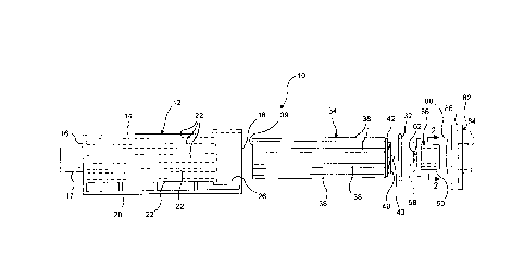
Figure 1 is an exploded view, partly in phantom, of the hinge
damper of the present invention.
Figure 2 is a cross-sectional view along plane 2-2 of Figure
1.
Figure 3 is a front plan view of the clutch of the present
invention.
Figure 4 is a cross-sectional view along plane 4-4 of Figure
3.
Figure 5 is a front plan view of the cylindrical rotor of the
present invention.
Figure 6 is a cross-sectional plan view showing the engagement
of the rotor to the clutch.
DETAILED DESCRIPTION OF THE PREFERRED EMBODIMENT
Referring now to the drawings in detail wherein like numerals
refer to like elements throughout the several views, one sees that
Figure 1 is an exploded view of one-way hinge damper 10 of the
present invention.
Housing 12 is generally cylindrical and is formed from
cylindrical wall 14, closed end 16 and open end 18. Closed end 16
is affixed to cylindrical detent stub 17 which is affixed to one of
the structures (not shown) for which rotational damping is desired,
such as the instrument panel of an automobile (not shown) , to which
3

CA 02302847 2000-03-28
the glovebox door (not shown) is rotationally damped. Similarly,
longitudinally oriented support 20 is affixed to cylindrical wall
14 to aid in the handling or securing of housing 12. The interior
of cylindrical wall 14 can be smooth, but can optionally include
longitudinal grooves 22 in order to increase the damping function
of silicone 24 or other similar viscous damping fluid or gel which
fills housing 12 (see Figure 6).
Open end 18 includes widened mouth 26. Cylindrical rotor 34
is received with cylindrical wall 14 of housing 12 with a small gap
36 therebetween (see Figure 6) which is filled with silicone 24.
The exterior of cylindrical rotor 34 is preferably smooth, but can
optionally include longitudinal passageways 38 leading to the
hollow interior of cylindrical rotor 34 to increase the damping
function of silicone 24. The forward end 40 of cylindrical rotor
34 includes portion 42 of slightly reduced diameter in order to be
engaged by seal 32. As shown in Figures 3 and 4, forward end 40 of
cylindrical rotor 34 further includes central pin 43 about which
flat or longitudinally level sections 44, 46, 48, 50 rotationally
alternate with tamped (or sloped) sections 45, 47, 49, 51. In the
configuration shown in Figure 3, tamped sections 45, 47, 49, 51
ramp upwardly in the counter-clockwise direction. Hence, radially
extending walls 52, 53, 54, 55 are formed at the intersection of
flat and sloped sections 44, 45, sections 46, 47, sections 48, 49,
and sections 50, 51, respectively.
Clutch 56 includes central aperture 58 which receives central
pin 43 of cylindrical rotor 34 to maintain radial alignment of
4

CA 02302847 2000-03-28
clutch 56 and cylindrical rotor 34. Similarly, while not shown,
rear end 39 of cylindrical rotor 34 can include structure to
rotationally engage an interior surface of closed end 16 of housing
12 to maintain radial alignment of cylindrical rotor 34. Clutch 56
is integr~ with output shaft 60, which is typically affixed to a
structure (not shown) for which rotational damping is desired, such
as the door of an automotive glovebox (not shown) . As shown in
Figure 2, output shaft 60 may have interior aperture 61 with
inwardly facing detents 63, although other configurations may be
used depending upon the application as would be apparent to those
skilled in the art. Face 62 of clutch 56 engages against forward
end 40 of cylindrical rotor 34 and, as shown in Figure 5, includes
a similar configuration of flat or longitudinally level sections
64, 66, 68, 70 rotationally alternating with ramped sections 65,
67, 69, 71, and radially extending walls 72, 73, 74, 75 formed
between the portions of ramped sections 65, 67, 69, 71 and
rotationally adjacent flat sections 64, 66, 68, 70. With this
configuration, when viewed from the perspective of output shaft 60
(from the right toward the left in the orientation shown in Figure
1), when output shaft 60 is turned clockwise, radially extending
walls 52, 53, 54, 55 of forward end 40 of cylindrical rotor 34
align with corresponding radially extending walls 72, 73, 74, 75 of
face 62 of clutch 56 and cylindrical rotor 34 is rotated through
silicone 24 or other similar viscous damping fluid or gel thereby
providing damping. However, when output shaft 60 is turned
counter-clockwise, ramped sections 45, 47, 49, 51 of forward end 40

CA 02302847 2000-03-28
of cylindrical rotor 34 "ramp over" or slide over corresponding
ramped sections 65, 67, 69, 71 of face 62 of clutch 56 thereby not
rotating cylindrical rotor 34 and resulting in essentially no
damping of clutch 56 and output shaft 60. A typical application
for such a~configuration is to have damping as a glovebox door (not
shown) is opened, but no damping as the glovebox door is closed.
The positioning of where clutch 56 engages cylindrical rotor
34 can be determined by dividing a circle by the number of ramped
sections used. For instance, for engagement every ninety degrees,
four ramped sections are used as disclosed herein.
Wave spring 80 includes central aperture (not shown) through
which output shaft 60 passes so that wave spring 80 abuts clutch
56. Wave spring 80 has a washer-type shape but includes
circumferential undulations or waves to provide a spring function
in the longitudinal direction.
Cap 82 includes central aperture 84 through which output shaft
passes 60 and circumferential flange 86 which is secured to the
outer periphery of open end 18 of housing 12. Additionally, cap 82
secures wave~-spring 80 in a biased position against clutch 56
thereby biasing clutch 56 against forward end 40 of cylindrical
rotor 34.
Typically, housing 12, cylindrical rotor 34, clutch 56 and cap
82 are formed of molded plastic. Seal 32 is typically rubber and
wave spring 80 is typically metallic.
To assemble one-way hinge damper 10, the assembler partially
fills housing 12 with silicone 24 or other similar viscous damping
6

CA 02302847 2000-03-28
fluid or gel. The assembler then inserts cylindrical rotor 34 into
housing 12 and inserts seal 32 onto portion 42 of slightly reduced
diameter of cylindrical rotor 34. Clutch 56 is placed over forward
end 40 of cylindrical rotor 34 so that ramped sections 65, 67, 69,
71 of clu..~ch 56 align with ramped sections 45, 47, 49, 51 of
cylindrical rotor 34. Wave spring 80 is placed around output shaft
60 and cap 82 is snapped or welded into place.
To install one-way hinge damper 10, cylindrical detent stub 17
is affixed to a first structural element and output shaft 60 is
attached to a second structural element so that the desired
directional damping characteristics are achieved.
Thus the several aforementioned objects and advantages are
most effectively attained. Although a single preferred embodiment
of the invention has been disclosed and described in detail herein,
it should be understood that this invention is in no sense limited
thereby and its scope is to be determined by that of the appended
claims.
7

Representative Drawing
A single figure which represents the drawing illustrating the invention.
Administrative Status

2024-08-01:As part of the Next Generation Patents (NGP) transition, the Canadian Patents Database (CPD) now contains a more detailed Event History, which replicates the Event Log of our new back-office solution.

Please note that "Inactive:" events refers to events no longer in use in our new back-office solution.

For a clearer understanding of the status of the application/patent presented on this page, the site Disclaimer , as well as the definitions for Patent , Event History , Maintenance Fee  and Payment History  should be consulted.

Event History

Description Date
Inactive: IPC assigned 2022-11-14
Inactive: IPC expired 2017-01-01
Time Limit for Reversal Expired 2007-03-28
Letter Sent 2006-03-28
Inactive: IPC from MCD 2006-03-12
Grant by Issuance 2004-11-02
Inactive: Cover page published 2004-11-01
Pre-grant 2004-08-19
Inactive: Final fee received 2004-08-19
Notice of Allowance is Issued 2004-03-01
Letter Sent 2004-03-01
Inactive: Approved for allowance (AFA) 2004-01-29
Amendment Received - Voluntary Amendment 2003-11-27
Inactive: S.30(2) Rules - Examiner requisition 2003-06-04
Inactive: Cover page published 2000-10-08
Application Published (Open to Public Inspection) 2000-10-08
Inactive: First IPC assigned 2000-06-08
Inactive: IPC assigned 2000-06-08
Inactive: Filing certificate - RFE (English) 2000-04-26
Letter Sent 2000-04-26
Application Received - Regular National 2000-04-26
Request for Examination Requirements Determined Compliant 2000-03-28
All Requirements for Examination Determined Compliant 2000-03-28

Abandonment History

There is no abandonment history.

Maintenance Fee

The last payment was received on 2004-03-15

Note : If the full payment has not been received on or before the date indicated, a further fee may be required which may be one of the following

  • the reinstatement fee;
  • the late payment fee; or
  • additional fee to reverse deemed expiry.

Patent fees are adjusted on the 1st of January every year. The amounts above are the current amounts if received by December 31 of the current year.
Please refer to the CIPO Patent Fees web page to see all current fee amounts.

Fee History

Fee Type Anniversary Year Due Date Paid Date
Application fee - standard 2000-03-28
Registration of a document 2000-03-28
Request for examination - standard 2000-03-28
MF (application, 2nd anniv.) - standard 02 2002-03-28 2002-03-07
MF (application, 3rd anniv.) - standard 03 2003-03-28 2003-03-13
MF (application, 4th anniv.) - standard 04 2004-03-29 2004-03-15
Final fee - standard 2004-08-19
MF (patent, 5th anniv.) - standard 2005-03-29 2005-03-04
Owners on Record

Note: Records showing the ownership history in alphabetical order.

Current Owners on Record
ILLINOIS TOOL WORKS INC.
Past Owners on Record
STEVEN L. BIVENS
Past Owners that do not appear in the "Owners on Record" listing will appear in other documentation within the application.
Documents

To view selected files, please enter reCAPTCHA code :


To view images, click a link in the Document Description column. To download the documents, select one or more checkboxes in the first column and then click the "Download Selected in PDF format (Zip Archive)" or the "Download Selected as Single PDF" button.

List of published and non-published patent-specific documents on the CPD .

If you have any difficulty accessing content, you can call the Client Service Centre at 1-866-997-1936 or send them an e-mail at CIPO Client Service Centre.


Document
Description 
Date
(yyyy-mm-dd) 
Number of pages   Size of Image (KB) 
Representative drawing 2000-10-02 1 6
Description 2003-11-26 8 288
Abstract 2000-03-27 1 39
Description 2000-03-27 7 268
Claims 2000-03-27 3 83
Drawings 2000-03-27 2 43
Claims 2003-11-26 3 79
Courtesy - Certificate of registration (related document(s)) 2000-04-25 1 113
Filing Certificate (English) 2000-04-25 1 164
Reminder of maintenance fee due 2001-11-28 1 112
Commissioner's Notice - Application Found Allowable 2004-02-29 1 161
Maintenance Fee Notice 2006-05-22 1 172
Correspondence 2004-08-18 1 29