Note: Descriptions are shown in the official language in which they were submitted.
CA 02302983 2000-03-22
99/062 SF
FUEL SYNTHESIS
Background of the Invention
The present invention relates to a method of trans-
forming a normally gaseous composition containing at least
one hydrogen source, at least one oxygen source and at
least one carbon source into a normally liquid fuel, fur-
thermore the present invention relates to a normally liquid
fuel and to an apparatus for transforming a normally gase-
ous composition into a normally liquid fuel.
One of the major problems facing mankind is the global
warming of the atmosphere due to man-made emissions of
greenhouse gases such as carbon dioxide, methane, chloro-
fluorocarbons, nitrous oxide or ozone. One possible appro-
ach to mitigate the emissions of these greenhouse gases to
the atmosphere would be to recycle them in a chemical
process to form useful products. Among all the man-made
greenhouse gases, methane and carbon dioxide contribute to
most of the greenhouse effect.
Prior Art
Intensive investigations have been carried out either
to convert methane into higher hydrocarbons by oxidative
coupling of methane as well as to convert methane into
methanol by partial oxidation of methane (reports of R. H.
Crabtree et al. in Chem. Rev..95 (1995) 987 and of H. D.
Gesser, N.R. Hunter and C.B. Prakash in Chem. Rev. 85
(1985) 235; both reports being incorporated herein for all
purposes by way of reference). However, the yield of objec-
tive products from these conventional catalytic methane
conversions is too low for a practical application.
CA 02302983 2000-03-22
2 99/062 SF
A great effort has also given to chemical fixation of
carbon dioxide. Heterogeneous catalysis has been considered
to be a desirable route for carbon dioxide utilization. But
a large amount of additional energy or expensive hydrogen
is required for conventional catalytic utilization of
carbon dioxide since the carbon dioxide molecule has a very
low energy content. There is still no confirmed technology
by far for utilizing such a plentiful carbon source.
A few processes for the synthesis of liquid fuel star-
ting from gaseous compositions are known, such as the
"Mobil process" and the "Fischer-Tropsch process" schema-
tically shown in equation (1) and (2).
CO + HZ -~ CH30H ~ gasoline ( 1 )
CO + HZ -~ gasoline ( 2 )
For both heterogeneous catalyzed processes the produc-
tion of "synthesis gas", a mixture of CO and Hz also named
"syngas", represents the first step along the path to
methanol and gasoline respectively. Even if the "Mobil pro-
cess" (eq. (1)) and the "Fischer-Tropsch process" (eq. (2))
are practiced today for industrial fuel synthesis produc-
tion, e.g in South Africa, Malaysia and New Zealand, they
are non-economic "political processes", heavily supported
by governmental subsidies. The lack of profitableness is
either due to the usually required high pressures at which
the processes take place as well as to the high production
costs of syngas and the fact that the produced syngas needs
to be compressed before applied in the processes (1) and
(2). Thus, about 60o to 80°s of the total cost of the pro-
cesses (1) and (2) goes to production and compression of
syngas.
The industrial production of syngas mostly derives from
the energy-intensive steam reforming of methane shown in
CA 02302983 2000-03-22
99/062 SF
equation ( 3 )
H20 + CH9 ~ CO + 3 H2 ~H° = 2 0 6 . 1 kJ/mo 1 ( 3 )
Syngas can also be produced from the greenhouse gases
methane and carbon dioxide as shown in equation (4). Howe-
ver, such a reforming of carbon dioxide by methane is also
a very energy-intensive process and requires high tempera-
tures. Moreover, deposition of carbon on the catalyst
always causes problems for this reaction.
COZ + CH4 ~ 2 CO + 2 Hz ~H° = 258.9 kJ/mol (4)
Non-equilibrium plasma chemical processes occuring in
the volume part of electrical non-equilibrium discharges
have attracted a great deal of interest. Particularly,
silent gas discharges have demonstrated its suitability for
large-scale industrial applications. The ozone generation,
as its most important industrial application so far, is
described by Eliasson et al. in IEEE Transactions on Plasma
Science, Vol. 19 (1991), page 309-323 (this report being
incorporated herein for all purposes by way of reference).
It is to be noted that a characteristic of the silent
discharge is the presence of a dielectric. Therefore silent
gas discharges are also referred to as dielectric barrier
discharges.
Recently, the utilization of greenhouse gases for the
synthesis of methanol or methane in such silent gas disch-
arge reactors has also been described. Thus, DE 42 20 865
describes a method and an apparatus for the hydrogenation
of carbon dioxide leading in particular to methane or
methanol by exposing a mixture of carbon dioxide and a
substance containing hydrogen atoms, preferably hydrogen or
water, to a dielectric barrier discharge. An overview of
the progress in this field have been summarized by Eliasson
et a1. in Energy Conversion Management 38 (1997) 415 (this
CA 02302983 2000-03-22
4 99/062 SF
report being incorporated herein for all purposes by way of
reference). It is noteworthy, however, that the reported
maximum yield of methanol was only about 1%.
Objects of the Invention
Accordingly, it is an object of the present invention
to provide for a method of transforming a normally gaseous
composition into a normally liquid fuel, which method can
be carried out economically, preferably at low pressures.
It is another object of the present invention to provi-
de for a method of producing liquid fuel from gaseous
compositions in reasonable yields and in a direct manner,
i.e. making the expensive formation of syngas no longer
necessary.
Another object of the present invention is to provide
for an apparatus that allows the transformation of a gase-
ous composition into a liquid fuel.
Further objects and advantages of the present invention
will become apparent as this specification proceeds.
Brief Summary of the Invention
We have found that the objects can be achieved accor-
ding to a first general embodiment of the invention by a
method as set forth in claim 1. Accordingly, the invention
provides for a method of transforming a normally gaseous
composition containing at least one hydrogen source, at
least one oxygen source and at least one carbon source into
a normally liquid fuel, wherein the gaseous composition
consists at least in part of carbon dioxide as the carbon
source and the oxygen source, and of methane as the
CA 02302983 2000-03-22
99/062 SF
hydrogen source and as a second carbon source, which method
comprises the steps of feeding the gaseous composition into
a reactor that includes a first electrode means, a second
electrode means and at least one layer of a normally solid
5 dielectric material positioned between said first and said
second electrode means, submitting the composition within
the reactor to a dielectric barrier discharge in the
presence of a normally solid catalyst, wherein said
normally solid catalyst is a member selected from the group
of zeolites, aluminophosphates, silicoaluminophosphates,
metalloaluminophosphates and metal oxides containing OH
groups, and controlling the dielectric barrier discharge to
convert the gaseous composition into the normally liquid
fuel. Typically, the normally solid catalyst is selected
from the group commonly designated as shape-selective
catalysts.
In a second general embodiment the invention provides
for a normally liquid fuel obtainable by a dielectric bar-
rier discharge, the normally liquid fuel comprising at
least 60 mol% of hydrocarbons having a normal boiling range
of between about 50°C and about 210°C, and less than 10 molo
of oxygenated hydrocarbons.
In a third general embodiment the invention provides
for an apparatus for transforming a normally gaseous compo-
sition containing at least one hydrogen source, at least
one oxygen source and at least one carbon source into a
normally liquid fuel as set forth in claim 9.
Definitions, Detailed Description of Preferred Embodiments
and Elements of the Invention
The term "about" as used herein before any numeral
implies a variation of typically ~ 100.
CA 02302983 2000-03-22
6 99/062 SF
The term "normal" with regard to boiling points, boi-
ling ranges, physical states of matter and the like indica-
tes that the value is understood as being corrected for
"normal conditions", i.e. a temperature of 25~C and an
atmospheric pressure of 1013 mbar.
The term "layer" is used herein to refer to any planar
or curved stratum having a width dimension that is
substantially larger than its thickness dimension; typical-
ly, the width: thickness ratio is at least 10:1 and general-
ly well above that value.
Sources of gaseous compositions containing methane
and/or carbon dioxide are for example fermentation gas,
natural gas or any waste and exhaust gases deriving from
industrial processes and containing methane and/or carbon
dioxide. It is, however, in accordance with and within the
scope of the present invention to use commercially availa-
ble methane and carbon dioxide of any purity or any other
source of methane and/or carbon dioxide known to the man
skilled in the art.
According to a preferred embodiment of the present
invention the molar ratio of carbon dioxide and methane
COZ:CHQ is between about 1:1 to about 1:4, preferably
between about 1:2 to about 1:3.
The preferred solid catalyst is a zeolite selected from
the group of zeolite X, zeolite Y, zeolite A, zeolite ZSM-5
and zeolite 13X.
In a further preferred embodiment of the invention, the
normally solid catalyst comprises at least one substance
selected from the group of metal ions and group IA, IIa,
IB, IIb and VIII elements of the periodic table. The latter
mentioned elements, i.e. alkali, earth alkali elements as
well as the elements of the zinc and the copper group and
CA 02302983 2000-03-22
7 99/062 SF
the iron groups of the periodic table can be present either
in ionic or atomic form. Those normally solid catalysts are
synthesized by procedures generally known to the man skil-
led in the art, such as any type of ion exchange reactions
in the case of zeolites. Examples of those solid catalysts
are the zeolites NaY, NaX, NaA or Fe-ZSM-5.
Particularly, the use of zeolites as the normally solid
catalyst limits the growth of the hydrocarbon chain and
thus inhibits the undesired formation of solid polymer.
Consequently, an increased production and yield respective-
ly of liquid fuel results. Moreover, applying "shape-selec-
tive catalysts", such as zeolites, leads to a large amount
of branched hydrocarbons representing a higher-quality
fuel.
The term "shape-selective catalyst" is intended to
refer to a catalyst that owns a special structure to limit
the diffusion of the reacting molecules and the formed
product molecules through its framework. Only molecules
with diameters smaller than the openings or pores of the
shape-selective catalyst can pass through the catalyst.
Moreover, an additional constraint is imposed by the size
and shape of the pores with respect to possible transition
states of the reaction.
Furthermore, the use of zeolites as the normally solid
catalyst offers the advantage of having high concentrations
of OH groups on the zeolite surfaces, i.e. on the outer
surfaces of the zeolite as well as within the zeolite
cavities. In addition to the high concentration of OH
groups on zeolite surfaces, an important characteristic of
zeolites is the natural coulombic field formed within the
zeolite framework. Within this context, it should be noted
that both the concentration of OH groups and the strength
of the natural coulombic field are controllable and ad-
justable. Generally, these two features allow the zeolites
CA 02302983 2000-03-22
8 99/062 SF
to easily respond to an external electric field, i.e. the
zeolite becomes electrically charged more easily. The
control of the dielectric barrier discharge according to
the invention allows though to control these charges and
electrostatic fields and, therefore, to control zeolite
activity and selectivity in the conversion of a gaseous
composition into a normally liquid fuel.
Typically, an operating pressure in the range of from
about 0.1 bar to about 30 bar at an operating temperature
up to about 400~C is maintained in the reactor.
Preferably, the layer of the normally solid dielectric
material has a thickness of between about 0.1 mm to about 5
mm and the dielectric constant of the normally solid die-
lectric material is between about 2 to about 20 .
In another preferred embodiment of the invention, the
normally solid dielectric material is at least partially
formed by the normally solid catalyst.
The normally liquid fuel obtainable by a dielectric
barrier discharge comprises at least 60 mol% of hydrocar-
bons, typically at least 90 moles of hydrocarbons, and
preferably at least 95 molo of hydrocarbons having a boi-
ling range of between about 50~C and about 210~C, typically
between about 50~C and about 180°C and a ratio branched
hydrocarbons: linear hydrocarbons of higher than 6:1, typi-
cally about 9:1. The normally liquid fuel generally con-
to ms less than 10 mol% of oxygenated hydrocarbons, such as
methanol, ethanol or higher, typically branched oxygenates.
Typically, the normally liquid fuel comprises less than 5
moll and preferably less than 2 mol% of oxygenated hydro-
carbons. In particular, the selectivity towards methanol is
generally less than 2 mol%, typically less than 1 mol% and
preferably less than 0.5 mol%.
CA 02302983 2000-03-22
9 99/062 SF
In a preferred embodiment of the apparatus according to
the invention the normally solid catalyst is a member
selected from the group of zeolites, aluminophosphates,
silicoaluminophosphates, metalloaluminophosphates and metal
oxides containing OH groups. Preferably, the normally solid
catalyst is a zeolite being a member selected from the
group of zeolite X, zeolite Y, zeolite A, zeolite ZSM-5,
zeolite 13X.
In another preferred embodiment of the inventive appa-
ratus, the normally solid catalyst comprises at least one
substance selected from the group of metal ions and group
IA, IIa, IB, IIb and VIII elements of the periodic table.
Typically, the layer of the normally solid dielectric
material has a thickness of between about 0.1 mm to about 5
mm. The dielectric material has preferably a dielectric
constant of between about 2 to about 20.
In a further preferred embodiment of the inventive
apparatus, the first electrode means has a first effective
electrode surface and the second electrode means has a
second effective electrode surface, the at least one layer
of the normally solid dielectric material covering at least
a potion of the effective surface of at least or.e of the
first and the second electrode means, the normally solid
catalyst covering at least a portion of the layer of the
normally solid dielectric. Typically, the first and the
second electrode means each have an essentially tubular
form, one of the first and the second electrode means
forming an outer shell while the other of the first and the
second electrode means forms an inner shell; the inner
shell being distanced from the outer shell by an essen-
tially tubular gap; the at least one layer of the normally
solid dielectric material being arranged in an essentially
tubular form and covering at least a portion of the inner
CA 02302983 2000-03-22
99/062 SF
and/or the outer shell; the normally solid catalyst being
arranged in an essentially tubular form and covering at
least a portion of the at least one layer of the normally
solid dielectric. Preferably, the tubular form is essenti-
5 ally cylindrical.
In another preferred embodiment of the inventive appa-
ratus, the first and the second electrode means each are
provided by at least one essentially planar structure, the
10 first electrode being distanced from the second electrode
means by at least one essentially planar gap; the at least
one layer of the normally solid dielectric being provided
by at least one essentially planar structure and covering
at least a portion of the first and/or the second electrode
means; the normally solid catalyst being provided by at
least one essentially planar form and covering at least a
portion of the at least one layer of the normally solid
dielectric material.
Typically, a plurality of pairs of first and said
second electrode means are arranged in an essentially
parallel or staked configuration forming a plurality of
gaps, the gaps being connected in series to form an elon-
gated path for passage of said normally gaseous mixture.
In a further preferred embodiment of the inventive
apparatus, the normally solid dielectric material is at
least partially formed by the normally solid catalyst.
Brief Description of the Drawings
For a better understanding of the nature and scope of
the present invention - and not to limit the invention -
preferred embodiments and details of the inventive method
and apparatus are described in more detail in the following
by reference to the drawings, in which:
CA 02302983 2000-03-22
11 99/062 SF
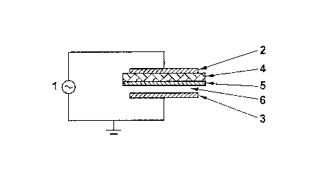
Fig. 1 is a diagrammatic cross sectional view of a
preferred dielectric barrier discharge reactor configura-
tion according to the invention;
Fig. 2 is a diagrammatic cross sectional view of a
further preferred dielectric barrier discharge reactor
configuration according to the invention;
Fig. 3 is a schematic representation of possible hydro-
carbon chain growth pathways occuring in the preferred
transformation of methane and carbon dioxide in a DBD
reactive system according to the invention.
Detailed Description of the Drawings
The dielectric barrier discharge is a high pressure
non-equilibrium discharge which occurs when alternating
voltages are applied to a gas space between two electrodes
separated by a non-conducting medium. Fig. 1 shows schema-
tically a cross sectional view of a dielectric barrier
discharge reactor according to the invention. The high
voltage AC generator 1 is connected to the first electrode
2 and to the second grounded electrode 3 both having an es-
sentially cylindrical form. The electrodes are generally
made of corrosion-resistant metals or alloys or of materi-
als covered by at least one layer of an electrically con-
ducting substance. Electrode 2 forms an outer shell and
Electrode 3 forms an inner shell. The dielectric layer 4 is
typically a glass, quartz or ceramic tube having a thick-
ness of between about 0.1 mm and about 5 mm and covers the
effective surface of electrode 2. The shape-selective
catalyst 5 shown in Fig. 1, is also formed in essentially
cylindrical form and is provided to cover the dielectric
layer 4. Typically, the dielectric tube 4 serves as support
for the solid catalyst 5. So, the solid catalyst 5, typi-
CA 02302983 2000-03-22
12 99/062 SF
cally in powder form, is disposed in a piece of gas-perme-
able quartz fleece and wrapped around the outer surface of
the dielectric tube 4, i.e. the surface of the dielectric
tube 4 facing towards the electrode 3. Further catalyst
support arrangements preferably used for the present die-
lectric barrier discharge reaction are described in EP-
899'O10 (the disclosure of which being incorporated herein
for all purposes by way of reference). It is obvious that
the form and the size of the solid catalyst, i.e. whether
it is applied in powder form or as grains of different
sizes and the manner by which the catalyst is supported,
i.e by means of the dielectric material and by means of an
additional support respectively, can be modified within the
scope of the present invention.
The normally gaseous composition passes through the
essentially cylindrical discharge gap 6, where it is expo-
sed to the dielectric barrier discharge. The dielectric
barrier discharge is effected by an AC potential applied
between the first electrode and the second electrode means.
The preferred AC potential being in the range of from about
6 kV to about 100 kV and the frequency of the AC potential
preferably being in the range of from about 50 Hz to about
1 MHz. The dielectric barrier discharge is controlled by
maintaining a current density in the range of between about
0.1 A/mZ and about 10 A/m2 as calculated for the effective
surface of one of the first and second electrodes. As
indicated above, an operating pressure in the range of from
about 0.1 bar to about 30 bar at an operating temperature
up to about 400~C is maintained in the reactor. The normally
gaseous mixture is passed through said reactor preferably
at a rate of from about 0.1 m3/hour to about 200 m3/hour.
When the amplitude of applied AC electric field reaches
a critical value, breakdown is initiated in the gas and a
current flows from one electrode to the other. Gnce break-
down is initiated at any location within the discharge gap,
charge accumulates on the dielectric leads to fcrmation of
CA 02302983 2000-03-22
13 99/062 SF
an opposite electric field. This opposite electric field
reduces the external electric field within the gap and
interrupts the current flow in a few nanoseconds to form
microdischarges. The duration of the current pulse relates
to pressure and properties of gases involved and the die-
lectrics applied. A large number of such microdischarges
will be generated when a sufficiently high AC voltage is
applied. The principal advantages of dielectric barrier
discharge are: it combines the large volume excitation of
glow discharges with high pressure characteristics of
corona discharges; the entire electrode area is effective
for discharge reactions.
Fig. 2 shows another preferred configuration of a
dielectric barrier discharge reactor according to the
invention. The corresponding electrodes, the layer of the
normally solid dielectric material and the normally solid
catalyst respectively of this embodiment have or are arran-
ged in an essentially planar form. Examples of the dielec-
tric material are glass, as indicated, as well as quartz,
ceramics, ZrOz or A1z03.
Further preferred dielectric barrier discharge reactor
configurations not being shown in the Figs. 1 and 2 are
those, where the solid catalyst either occupies an essen-
tial part of the discharge gap 6 or where the solid cata-
lyst covers only a portion of the dielectric material.
While not wishing to be bound by any specific theory
for explaining the findings which led to the present inven-
tion, the following consideration is presented:
The inventive method discloses the formation of a
liquid fuel, preferably higher hydrocarbons starting from a
normally gaseous composition, preferably methane and carbon
dioxide thus making the expensive formation of syngas no
longer necessary. It is considered that methyl radicals are
responsible for the initiation of these free radical chain
CA 02302983 2000-03-22
14 99/062 SF
reactions. The hydrocarbon chain growth pathways are also
very similar to pathways found in Fischer-Tropsch synthe-
sis. This could suggest a very important new pathway for
direct hydrocarbon formation at atmospheric pressure via
dielectric barrier discharge. Fig. 3 shows a schematically
representative of free radical chain pathways.
Another important finding is that the CO selectivity
did not increase with a significantly increasing in conver-
sion of carbon dioxide, while CO formation can be explained
from electron disssociation or dissociative attachment of
carbon dioxide in the plasma discharges. It seems to be
that the new formed CO will continue to react with plasma
species to produce hydrocarbons. Fig. 3 also shows a possi-
ble pathway for this hydrocarbon formation. It can be
expected that the new formed CO will take some extra energy
from discharge reactions and will be much easier to further
react with plasma species like H, compared to CO in ground
state with the catalytic F-T synthesis. On the other hand,
the dissociation reactions for CO production from carbon
dioxide will generate oxygen species at the same time. Some
oxygen species like 0 and O(1D) are very efficient for
generation of methyl radicals. O(1D) is also active for
methanol formation from methane.
Examples
Example 1
The feed gases, i.e. a mixture containing 50°s methane
and 50% carbon dioxide, were introduced into the system
flowing downstream through the reactor. The flow rate is
200 ml/min. The catalyst used is 13X zeolite. An alter-
nating voltage of about 10 kV with a frequency of about 30
kHz is applied to the electrodes. A dielectric barrier
discharge is thus initiated. The operating temperature is
maintained at about 200~C and the operating pressure is
CA 02302983 2000-03-22
15 99/062 SF
about 11 kPa. A back pressure valve at the exit of the
reactor was used to adjust the pressure. A MTI (Microsensor
Technology Inc., M20011) dual-module micro gas chromato-
graph containing a Poraplot Q column and a molecular sieve
5A Plot column with a TCD detector was used to detect
gaseous products. The gas sample was heated by a heated
line to avoid possible condenstaion before it was taken
into the GC. The liquid sample was also gas-chromatographi-
cally analysed. The results of the synthesis are reported
in Table 1, wherein the conversion of methane and carbon
dioxide respectively are defined as:
Conversion [CH4] - { ( [CH4] in - [CHa] out) / [CH9] gin} x 100 0
and
Conversion [COz] - { ( [COz] in - [COz] out) / [COz] gin} x 100 0
respectively. The selectivity of the products are defined
as:
Selectivity [prod.] -
{(number of carbon atoms of prod. x [prod.]out)/total carbon
amount converted} x 100%
The analysis of the gas sample reveals formation of
carbon monoxide C0, alkanes having 2 to 5 carbon atoms (C2-
C5) such as iso-butane and iso-pentane, unsaturated hydro-
carbons such as ethylene and acetylene, small amount of
oxygenated products such as CH30CH3, methanol and ethanol as
well as water and hydrogen. The analysis of the liquid
sample shows a high yield of gasoline components (C5-C11)
being rich in branched hydrocarbons. The ratio bran-
ched:linear hydrocarbons is about 9:1.
In Table 1, results from recently reported catalytic
Fischer-Tropsch synthesis (M. J. Keyser, R.C. Everson and
CA 02302983 2000-03-22
16 99/062 SF
R.L. Espinoza in Applied Catalysis A, Vol. 171 (1998) 99;
this report being incorporated herein for all purposes by
way of reference) are additionally listed for sake of
comparison. Evidently, the product distribution is very
similar for both processes, i.e. obtained by the inventive
dielectric barrier discharge synthesis (DBD synthesis) and
the Fischer-Tropsch synthesis (F-T synthesis). However, the
inventive method operates at low or atmospheric pressures,
whereas Fischer-Tropsch synthesis is performed at very high
pressures.
CA 02302983 2000-03-22
17 99/062 SF
Table 1 Synthesis performance results
Catalytic our DBD Synthesis
F-T-synthesis
gas temperature 220 202
(~C)
gas pressure (kpa) 500 11
Hz/CO 1/1
CH4/COz 1/1
Bed length (m) 0.25 0.30
GHSV (h-1) ~ 222
Flowrate (ml/min) 200
Power (w) 500
CO conversion (%) 14.0
COz conversion (%) 47.5
CH4 conversion (%) 48.8
carbon atom selectivity
(%)
CO 27.9
C1 10.8
Cz 5.4 8.9
C3 14.1 3.7
C4 9.2 1.0
C5+ 50.5 58.2
C1-OH 2 . 0 0 . 2 6
Cz-OH 3 . 8 0 . 00
1-C3-OH 2 . 6
1-Ca-OH 0. 4
C 5+-OH 0 . 19
Example 2
A gas mixture containing 80% methane and 20% carbon dioxide
is passing through the gap between the electrodes with the
CA 02302983 2000-03-22
18 99/062 SF
catalyst layer. The flow rate is 0.5 NI/min. The catalyst
used is 13X zeolite. An alternating voltage of about 10 kV
with a frequency of about 30kHz is applied to the
electrodes. A dielectric barrier discharge is thus
initiated. The operating temperature is maintained at about
150~C and the operating pressure is about 1 bar. The product
essentially consists of liquid fuel (C5 to C11), syngas
(CO/H2) and light gaseous hydrocarbons (C2 and C3). The
liquid fuel product, which is rich in branched hydrocarbons,
is collected in a condenser. Similar conversions and selec-
tivities as reported for Example 1 are found.
Example 3
The feed gases, i.e. a mixture containing 66.7% methane and
33.30 carbon dioxide, were introduced into the system
flowing downstream through the reactor. The flow rate is 150
ml/min. The catalyst used is 13X zeolite. An alternating
voltage of about 10 kV with a frequency of about 30 kHz is
applied to the electrodes. A dielectric barrier discharge is
thus initiated. The operating temperature is maintained at
about 150~C and the operating pressure is about 25 kPa. Under
such conditions, methane conversion is 39.5 and carbon
dioxide conversion is 33.8%. The selectivities for the
products are:
CO 32.60
C2 17.5°s
C3 12 . 9-°s
C4 6.60
C5+ 29.3%
The success in the research and development of a feasible
utilization of greenhouse gases, in particular methane and
carbon dioxide, which led to the present invention signify
the attainment of two important objectives: First, slowing
down a build-up of greenhouse gases in the atmosphere and,
CA 02302983 2000-03-22
19 99/062 SF
second, better carbon resource utilization. An extra ad-
vantage of such an utilization of these major greenhouse
gases is the fact that such synthesized liquid fuel does not
contain pollutants like sulfur that are usually present in
coal and petroleum.
Although certain preferred embodiments of the invention
have been described herein, it will be apparent to those
skilled in the art to which the invention pertains that
modifications and variations of the described embodiments
may be made without departing from the spirit and scope of
the invention.