Note: Claims are shown in the official language in which they were submitted.
What is claimed is:
1. A one-piece elongate traction stud, having an elongate axis, for an endless
snowmobile drive belt or the like comprising:
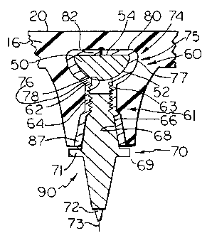
an axially inner cylindrical mounting end section for detachably mounting
to said endless drive belt,
an axially outer, ground engageable end, and
self-locking means, which radially outwardly diverges in an axially outer
direction, axially outwardly of said cylindrical mounting end section for
bearing
against a complementally formed axially outwardly diverging portion surface on
said snowmobile drive belt.
2. The one-piece traction stud set forth in claim 1 wherein said axially inner
cylindrical mounting end section comprises an axially extending external
thread
having a predetermined axial length; said sidewall section having a greater
predetermined axial length which is greater than said predetermined length.
3. The one-piece traction stud set forth in claim 1 wherein said cylindrical
mounting end comprises an externally thread of predetermined diameter and
predetermined length, said self-locking means comprises a sidewall section
having a breadth which exceeds said predetermined diameter of said thread.
4. A one-piece stud mount, having an elongate axis, for detachably mounting a
traction stud on an endless snowmobile drive belt, having inner and outer
surfaces, said stud mount comprising:
an elongate hollow one-piece endless annular band of material, having an
elongate axis, including
an axially inner, hollow, cylindrical mounting section formed about
said elongate axis and adapted to be embedded in said drive belt; and
an axially outer skirt, axially outward of said axially inner, hollow
cylindrical mounting section, which radially outwardly flares in an axially
outer
-30-
direction relative to said axially inner mounting section, for bearing against
a
complementally formed portion of said traction stud.
5. The one-piece stud mount set forth in claim 4 wherein said cylindrical
mounting section includes an internal thread having a predetermined diameter
and a predetermined length; said skirt having a predetermined greater length
which is greater than said predetermined length.
6. The one-piece stud mount set forth in claim 4 wherein said skirt has a
diameter which gradually increases in an axially outer direction.
7. The one-piece stud mount set forth in claim 5 wherein said skirt has a
frusto-
conical shape.
8. The one-piece stud mount set forth in claim 4 wherein said axially inner
mounting section is internally threaded for receiving a complementally
threaded
inner end of said traction stud.
9. The one-piece stud mount set forth in claim 4 including transverse mounting
head means integral with axially inner cylindrical mounting section for
mounting
said stud mount to a reinforcing rod adapted to be embedded in the endless
snowmobile drive belt.
10. The one-piece stud mount set forth in claim 9 wherein said transverse
mounting head means comprises a transverse wall transverse to said elongate
axis.
11. The one-piece stud mount set forth in claim 10 wherein said transverse
wall
comprises a cylindrical wall.
12. The one-piece stud mount set forth in claim 9 wherein said axially outer
skirt
comprises an annular sidewall of substantially uniform radial thickness.
13. The one-piece stud mount set forth in claim 12 wherein said transverse
mounting head means including a transverse wall of substantially uniform
thickness throughout its length.
-31-
14. A one-piece stud mount for mounting a traction stud, having a radially
outer
locking surface thereon, to an endless snowmobile drive belt said stud mount
comprising:
a one-piece member defining an elongate hollow passage therein, said
passage having an elongate axis;
said passage including
an axially inner internally threaded cylindrical sidewall for
detachably, threadedly receiving an externally threaded portion of a traction
stud;
and
axially outer, self-locking sidewall means, axially outward of said
axially inner threaded cylindrical sidewall, which diverges radially outwardly
in an
axially outward direction relative to said axially inner threaded cylindrical
sidewall
for bearing against a locking surface portion on said traction stud as said
traction
stud is threaded in one direction into said cylindrical sidewall to
frictionally
engage said locking surface portion and detachably inhibit said traction stud
from
being reversely rotated.
15. The one-piece stud mount set forth in claim 14 wherein said cylindrical
sidewall has a predetermined internal diameter and predetermined length, said
self-locking sidewall
means having a predetermined greater axial length which is greater than said
predetermined length.
16. The one-piece stud mount set forth in claim 15 wherein said cylindrical
sidewall has an internal diameter which is greater than said predetermined
diameter and gradually increases in an axially outer direction.
-32-
17. The one-piece stud mount set forth in claim 16 wherein said sidewall is
non-
threaded and provides a smooth, uninterrupted bearing surface for bearing
against a complementally formed, smooth bearing surface on said stud.
18. The one-piece stud mount set forth in claim 14 including a mounting head
means integral with axially inner cylindrical sidewall for mounting said stud
mount
to a reinforcing rod adapted to be embedded in the endless snowmobile drive
belt.
19. The one-piece stud mount set forth in claim 18 wherein said transverse
head comprises a transverse wall transverse to said elongate axis.
20. The one-piece stud mount set forth in claim 19 wherein said transverse
wall
comprises a cylindrical wall.
21. The one-piece stud mount set forth in claim 18 wherein said axially outer
skirt comprises an annular sidewall of substantially uniform radial thickness.
22. The one-piece stud mount set forth in claim 21 wherein said transverse
wall
is of substantially uniform thickness throughout its length.
23. A one-piece traction stud mount for detachably mounting an elongate
traction
stud, having an elongate axis of rotation and threaded and unthreaded
portions,
on an endless drive track, said stud mount comprising:
a hollow stud receptacle having an axially extending, circular, threaded
sidewall, provided with axially inner and outer ends, for threadedly rotatably
receiving a threaded portion of a traction stud to
axially relatively move said stud and said stud mount toward each
other when said stud and stud mount are relatively rotated in one direction,
and
for axially relatively moving said stud and stud mount away from
each other when said stud and stud mount are relatively reversely rotated in
an
opposite direction;
-33-
said stud receptacle including an axially outer, axially outwardly extending
truncated cone shaped, unthreaded sidewall having an axially inner, small
diameter end, axially outwardly adjacent said axially outer end of said
threaded
sidewall and an axially outer, large diameter, terminal end, larger than said
axially inner small diameter end.
24. The one-piece traction stud mount set forth in claim 23 wherein said
threaded
sidewall has a predetermined axial length, said truncated cone shaped sidewall
having an axial length which is greater than said predetermined length of said
threaded sidewall.
25. The one-piece traction stud mount set forth in claim 23 wherein said
circular
threaded sidewall has a predetermined diameter, said small diameter end having
a diameter at least as great as said predetermined diameter of said threaded
sidewall.
26. The one-piece stud mount set forth in claim 23 including a transverse head
integral with said threaded sidewall.
27. The one-piece stud mount set forth in claim 26 wherein said transverse
head comprises a transverse cylinder having a sidewall of substantially
uniform
thickness.
28. A one-piece traction stud mount for detachably mounting an elongate
traction
stud, having an elongate axis of rotation and threaded and unthreaded
portions,
on an endless drive track, said stud mount comprising:
a hollow stud receptacle, adapted to be at least partially embedded in an
endless drive track, having
a circular cylindrical internal sidewall surface of predetermined
internal diameter and with axially inner and outer ends, and
a truncated cone shaped internal sidewall surface axially outwardly
of said outer end of said circular cylindrical internal sidewall surface
including
-34-
a relatively small diameter circular end, having a first
diameter substantially equal to said predetermined diameter, making a smooth
relatively
uninterrupted transition from said axially outer end of said cylindrical
sidewall
surface, and
an axially opposite, relatively large diameter circular end of
substantially greater predetermined diameter which is greater than said first
diameter;
said internal sidewall surface being threaded to threadedly receive a
threaded portion of a traction stud.
29. A one-piece traction stud comprising:
an elongate shank having
an axially inner, threaded mounting end for mounting on an endless
drive track,
an opposite ground engageable end, and
an intermediate portion, between said ends, axially outwardly
adjacent said threaded mounting end;
said threaded mounting end including an externally threaded section of a
predetermined axial length;
said intermediate portion comprising a truncated cone having
a relatively small diameter circular end, integral with said mounting
portion, having a relatively small diameter substantially equal to said
predetermined diameter and
an axially opposite, relatively large diameter circular end of
substantially greater diameter.
-35-
30. A one-piece traction stud mount for detachably mounting a rotatable
traction
stud having threaded and non-threaded portions on an endless drive track, said
stud mount comprising:
a hollow, internally threaded, circular cylinder, having opposite ends, for
threadedly, rotatably receiving a threaded portion of a traction stud to
axially
relatively move said stud and stud mount toward each other as said stud and
stud mount are relatively rotated in one direction of rotation and for axially
relatively moving said stud and stud mount in an opposite direction of
rotation
when said stud and stud mount are relatively rotated in an opposite direction;
and
a hollow truncated cone integrally coupled to one end of said cylinder for
receiving and bearing against said non-threaded portion of said stud as said
stud
and stud mount are relatively rotated in said one direction to detachably lock
said
stud to said stud mount and inhibit relative rotation of said stud and stud
mount in
said opposite direction.
31. The stud mount set forth in claim 30 wherein said cylinder has a
predetermined internal diameter and said truncated cone has one end having an
internal diameter substantially equal to said predetermined diameter
integrally
coupled to said one end of said cylinder and an opposite circular end of
substantially greater diameter substantially which is greater than said
predetermined diameter.
32. The stud set forth in claim 31 wherein said truncated cone includes a
sidewall
with a gradually increasing diameter between said one end and said opposite
end of said cone.
33. A method of mounting an elongate traction stud to an endless drive track,
said stud having
a cylindrical inner threaded end section,
an axially outer ground engaging end, and
-36-
an intermediate portion between said threaded end and said axially outer
end of greater breadth than said threaded end to an endless drive belt, said
method comprising the steps of:
threadedly rotating said cylindrical inner threaded end section in one
direction of rotation into a complementally threaded cylindrical surface on
said
track to axially translate said stud toward said track; and
compressing said intermediate portion of said stud against a
complementally formed surface on said track radially outward of said threaded
cylindrical surface to
axially force said stud against said complementally formed surface to
detachably
lock said stud to said track and inhibit reverse rotation of said stud;
said intermediate portion including an intermediate self-locking section
which has a breadth that gradually increases in an axially outer direction,
and
said complementally formed surface on said track comprising a radially
outwardly
tapering surface, said compressing step being accomplished by axially inwardly
moving said intermediate self-locking section which has a breadth that
gradually
increases in an axially outer direction against a complementally formed
radially
outwardly tapering surface.
34. A traction stud for mounting on an endless drive track comprising:
an elongate shank, having an elongate axis, including
an axially inner end of predetermined diameter for mounting in an
endless drive track;
an axially outer ground engageable end, and
an intermediate stud locking section, between said ends, having
axially spaced annular portions of progressively increasing diameter, in an
axially
-37-
outer direction, greater than said predetermined diameter for frictionally
engaging
a complementally formed stud mounting portion of said track.
35. The one-piece traction stud set forth in claim 34 wherein said axially
inner
end includes an external thread of predetermined axial length for threading
into a
complementally threaded stud mounting portion of said track; said stud locking
section comprising an annular sidewall which diverges radially outwardly in an
axially outer direction.
36.The one-piece traction stud set forth in claim 35 wherein said annular
sidewall
includes an axially innermost end having a diameter substantially equal to
said
predetermined diameter.
37. The one-piece traction stud set forth in claim 36 wherein said sidewall
has an
axial length which is greater greater than said predetermined axial length of
said
thread.
38. In combination:
a one-piece elongate traction stud having an elongate axis, for an endless
drive track including
an axially inner externally threaded mounting end,
an axially outer ground engageable end, and
an intermediate section between said ends having an axially outer
portion;
a one-piece stud mount for mounting said traction stud on said endless
drive track comprising a hollow annular band including
an axially inner, internally threaded circular cylindrical section of
predetermined diameter for threadedly receiving said externally threaded
mounting end to relatively move said stud and said stud mount toward each
other
when relatively rotated about said axis in one direction and to relatively
axially
-38-
move said stud and said stud mount away from each other when reversely
rotated in an opposite direction, and
an axially outer, self-locking member;
said axially outer portion of said intermediate section of said stud and said
axially outer member of said stud mount including complementally formed self-
locking surfaces which have a breadth greater than said predetermined diameter
and which frictionally mate when said stud and said stud mount are relatively
rotated in said one direction to inhibit said stud and said stud mount from
being
reversely rotated in said opposite direction.
39. The combination set forth in claim 38 wherein said intermediate section
includes axially spaced annular portions of progressively increasing diameters
in
an axially outer direction.
40. The combination set forth in claim 38 wherein said intermediate section
comprises an annular sidewall which diverges radially outwardly in an axially
outer direction.
41. The combination set forth in claim 40 wherein said intermediate section
comprises an outer surface which tapers radially outwardly in an axially outer
direction to provide a tapering surface for bearing against said axially outer
self-
locking member of said stud mount.
42. The combination set forth in claim 40 wherein said intermediate section of
said stud and said axially outer portion of said stud mount include
complementally formed portions which are inclined radially outwardly in an
axially
outer direction.
43. The combination set forth in claim 40 wherein said complementally formed
self-locking surfaces have complementally formed diameters which progressively
increase in an axial outer direction.
-39-
44. The combination set forth in claim 38 wherein said complementally formed
self-locking surfaces flare radially outwardly in an axially outer direction.
45. The combination set forth in claim 40 wherein said self-locking surface of
said
stud comprises a sidewall section which diverges radially outwardly in an
axially
outer direction and said self-locking surface of said stud mount comprises an
annular sidewall which flares radially outwardly in an axially outer direction
complemental to said sidewall section of said stud for frictionally receiving
said
sidewall section of said stud.
46. The combination set forth in claim 45 wherein said sidewall section has a
predetermined axial length; said sidewall section and said annular sidewall
each
having an axial length which is greater than the axial length of said
externally
threaded mounting end of said traction stud.
47. The combination set forth in claim 38 wherein said axially outer self-
locking
member of said stud mount has the shape of a truncated cone.
48. A stud mount for mounting a traction stud on an endless drive belt having
at
least one reinforcing rod embedded therein, said stud mount including
a cylindrical barrel, adapted to be disposed in said endless drive belt,
having inner and outer ends and an axis and defining a first opening
therethrough;
said barrel being internally threaded for threadedly detachably mounting
said traction stud; and
axially inwardly tapering locking means mounted on said outer end of said
barrel and responsive to axial movement of said stud toward said mount as said
stud is threaded into said barrel in one direction of rotation for bearing
against a
portion of said stud and detachably frictionally locking said stud to said
mount.
-40-
49. The stud mount set forth in claim 48 wherein said locking means comprises
an annular flange, which radially outwardly diverges in an axially outward
direction, integral with said outer end of said barrel.
50. The stud mount set forth in claim 49 wherein said flange has the
geometrical
shape of a frustum.
51. The stud mounting set forth in claim 49 wherein said flange is non-
threaded.
52. The stud mount set forth in claim 51 wherein said locking means comprises
an annular sidewall which outwardly diverges in an axially outer direction.
53. The stud mount set forth in claim 51 wherein said locking means has a
geometrical shape of a frustum integrally coupled to said outer end of said
threaded barrel.
54. The stud mount set forth in claim 48 wherein said locking means comprises
an annular wall which has the geometrical shape of a frustum integral with
said
outer end of said barrel.
55. The stud mount set forth in claim 48 including mounting head means
mounted on said inner end of said barrel for mounting said barrel on said
reinforcing rod.
56. The stud mount set forth in claim 55 wherein said mounting head means
extends transversely to said barrel.
57. The stud mount set forth in claim 55 wherein said mounting head means
comprises a hollow band integral with said barrel, having a second opening
therein, and extending transversely to said first opening for being snugly
received
on said reinforcing rod.
58. The stud mount set forth in claim 57 wherein said mounting head means
includes a transverse opening therein, transverse to said first opening,
having an
outline shaped complementally to said outline of said predetermined
reinforcing
rod for mating therewith.
-41-
59. The stud mount set forth in claim 58 wherein said mounting head means
comprises a hollow band integrally coupled to said cylindrical barrel,
defining
said transverse opening therein, and extending transversely to said first
opening
for being received on said reinforcing rod.
60. The stud mount set forth in claim 59 wherein said hollow band comprises a
hollow elongate cylinder having a sidewall extending normal to said barrel.
61. The stud mount set forth in claim 55 wherein said mounting head means is
integral with said barrel and includes a pair of confronting flanges each
including
an opening therein for receiving said rod.
62. The stud mount set forth in claim 61 wherein said flanges each include a
transversely extending ear integral with the flange adjacent said opening
therein
for bearing against said rod.
63. The stud mount set forth in claim 62 wherein said flanges are generally
parallel to each other and said ears extend normal to said flanges.
64. A stud mount for mounting a traction stud on an endless resilient belt
having
inner and outer surfaces with at least one opening provided in said outer
surface
and at least one reinforcing rod embedded in said belt adjacent said one
opening, said stud mount including:
a hollow elongate member, adapted to be disposed in said opening,
having a longitudinal axis, including
an axially inner, hollow internally threaded cylinder for threadedly
detachably mounting said traction stud; and
axially outer stud locking flange means, integral with said cylinder,
radially outwardly diverging in an axially outer direction relative to said
cylinder
for bearing against a portion of said stud and detachably locking said stud to
said
flange means in response to axial inward movement of said stud as said stud is
being turned about said
-42-
axis in one direction of rotation to inhibit rotation of said stud in an
opposite
direction of rotation opposite said one direction.
65. The stud mount set forth in claim 64 wherein said stud locking flange
means
comprises an annular sidewall having the geometrical shape of a frustum.
66. The stud mount set forth in claim 64 wherein said locking flange means
comprises an annular sidewall having a frusto-conical shape.
67. In combination:
an endless resilient drive belt for propelling a snowmobile along a surface;
traction increasing means for increasing the traction of said drive belt
comprising:
a one-piece elongate snowmobile traction stud, having an elongate
axis, including
an axially inner mounting end,
an axially outer end for engaging said surface, and
an intermediate section between said ends;
a one-piece annular stud mount for mounting said stud on said
track including
an axially inner section of predetermined breadth for
internally receiving said axially inner mounting end, and
an axially outer section;
said intermediate section of said stud and said axially outer section of said
stud mount having complementally formed mating surfaces, with a breadth which
is greater than said predetermined breadth, for detachably locking said stud
to
said stud mount.
-43-
68. The combination set forth in claim 67 wherein said intermediate section
and
said axially outer section include complementally formed sidewall surfaces
each
of which diverges radially outwardly in said axially outer direction.
69. The combination set forth in claim 68 wherein said axially inner section
of
said stud mount comprises an internally threaded cylinder of uniform internal
diameter and said axially outer section of said stud mount comprises an
annular
sidewall, having an axially inner end integral with said internally threaded
cylinder
and an axially outer terminal end, having an internal diameter which is
greater at
said axially outer end thereof than at said axially inner end thereof.
70. The combination set forth in claim 69 wherein said annular sidewall has an
internal diameter which progressively increases between said inner end thereof
and said outer end thereof.
71. The combination set forth in claim 70 wherein said axially inner mounting
end
and said axially inner section are complementally threaded; said
complementally
formed mating surfaces each having a breadth which increases in an axially
outer direction.
72. A one-piece, elongate traction stud, having an elongate rotational axis
and
axially inner and outer ends, for mounting on an endless snowmobile drive
belt,
said stud comprising:
an axially inner, cylindrical, threaded stud mounting end section at said
axially inner end for threadedly engaging a complementally threaded stud mount
on said belt to axially inwardly move said stud toward said stud mount when
said
stud is rotated in one direction of rotation relative to said stud mount and
for
axially outwardly moving
said stud away from said stud mount when said stud is rotated in an opposite
direction of rotation;
-44-
axially outwardly moving said stud away from said stud mount when said
stud is rotated in an opposite direction of rotation;
an axially outer ground engaging end section at said axially outer end; and
self-locking means between said axially inner threaded end section and
said axially outer ground engaging end section for detachably frictionally
locking
said stud to said stud mount on said belt as said stud is moved axially
inwardly to
inhibit reverse rotation of said stud in said opposite direction;
said self-locking means comprising a radially outer surface section which
tapers radially outwardly in an axially outer direction to provide a radially
outwardly, axially outwardly tapering surface for bearing against a
complementally formed surface on said stud mount.
73. A one-piece, elongate traction stud, having an elongate rotational axis
and
axially inner and outer ends, for mounting on an endless snowmobile drive
belt,
said stud comprising:
an axially inner, cylindrical, threaded stud mounting end section at said
axially inner end for threadedly engaging a complementally threaded stud mount
on said belt to axially inwardly move said stud toward said stud mount when
said
stud is rotated in one direction of rotation relative to said stud mount and
for
axially outwardly moving said stud away from said stud mount when said stud is
rotated in an opposite direction of rotation;
an axially outer ground engaging end section at said axially outer end; and
self-locking means between said axially inner threaded end section and
said axially outer ground engaging end section for detachably frictionally
locking
said stud to said stud mount on said belt as said stud is moved axially
inwardly to
inhibit reverse rotation of said stud in said opposite direction;
-45-
said self-locking means comprising a sidewall section which radially
outwardly diverges in an axially outward direction for bearing against a
complementally formed section on said stud mount.
74. The one-piece traction stud set forth in claim 73 wherein said axially
inner,
cylindrical threaded stud mounting end section includes an external thread
having a predetermined axial length; said sidewall section having a
predetermined greater axial length greater than said predetermined axial
length.
75. A one-piece, elongate traction stud, having an elongate rotational axis
and
axially inner and outer ends, for mounting on an endless snowmobile drive
belt,
said stud comprising:
an axially inner, cylindrical, threaded stud mounting end section at said
axially inner end for threadedly engaging a complementally threaded stud mount
on said belt to axially inwardly move said stud toward said stud mount when
said
stud is rotated in one direction of rotation relative to said stud mount and
for
axially outwardly moving said stud away from said stud mount when said stud is
rotated in an opposite direction of rotation;
an axially outer ground engaging end section at said axially outer end; and
self-locking means between said axially inner threaded end section and
said axially outer ground engaging end section for detachably frictionally
locking
said stud to said stud mount on said belt as said stud is moved axially
inwardly to
inhibit reverse rotation of said stud in said opposite direction;
said axially inner cylindrical threaded end section including an external
thread having a predetermined diameter; said self-locking means comprising an
intermediate frusto-conically shaped stud section having a diameter which
gradually increases in an axially outward direction.
-46-
76. A one-piece, elongate traction stud, having an elongate rotational axis
and
axially inner and outer ends, for mounting on an endless snowmobile drive
belt,
said stud comprising:
an axially inner, cylindrical, threaded stud mounting end section at said
axially inner end for threadedly engaging a complementally threaded stud mount
on said belt to axially inwardly move said stud toward said stud mount when
said
stud is rotated in one direction of rotation relative to said stud mount and
for
axially outwardly moving said stud away from said stud mount when said stud is
rotated in an opposite direction of rotation;
an axially outer ground engaging end section at said axially outer end; and
self-locking means between said axially inner threaded end section and
said axially outer ground engaging end section for detachably frictionally
locking
said stud to said stud mount on said belt as said stud is moved axially
inwardly to
inhibit reverse rotation of said stud in said opposite direction;
said self-locking means including inclined surface means which diverges
diametrically outwardly of said axially inner cylindrical threaded stud
mounting
end
section in an axially outward direction for frictionally engaging a
complementally
formed surface on said stud mount.
77. A one-piece, elongate traction stud, having an elongate rotational axis
and
axially inner and outer ends, for mounting on an endless snowmobile drive
belt,
said stud comprising:
an axially inner, cylindrical, threaded stud mounting end section at said
axially inner end for threadedly engaging a complementally threaded stud mount
on said belt to axially inwardly move said stud toward said stud mount when
said
stud is rotated in one direction of rotation relative to said stud mount and
for
-47-
axially outwardly moving said stud away from said stud mount when said stud is
rotated in an opposite direction of rotation;
an axially outer ground engaging end section at said axially outer end; and
self-locking means between said axially inner threaded end section and
said axially outer ground engaging end section for detachably frictionally
locking
said stud to said stud mount on said belt as said stud is moved axially
inwardly to
inhibit reverse rotation of said stud in said opposite direction;
said axially inner cylindrical threaded end section having a predetermined
diameter, said self-locking means comprises a radially outer non-threaded
surface having a diameter larger than said predetermined diameter.
78. The traction stud set forth in claim 77 wherein said self-locking means
includes a non-threaded right circular cylinder having a diameter
substantially
greater than said predetermined diameter.
79. The traction stud set forth in claim 77 wherein said self-locking means
comprises a plurality of right circular cylinders stacked end-to-end and
having
diameter which progressively increases in an axially outer direction.
80. A one-piece, elongate traction stud, having an elongate rotational axis
and
axially inner and outer ends, for mounting on an endless snowmobile drive
belt,
said stud comprising:
an axially inner, cylindrical, threaded stud mounting end section at said
axially inner end for threadedly engaging a complementally threaded stud mount
on said belt to axially inwardly move said stud toward said stud mount when
said
stud is rotated in one direction of rotation relative to said stud mount and
for
axially outwardly moving said stud away from said stud mount when said stud is
rotated in an opposite direction of rotation;
an axially outer ground engaging end section at said axially outer end; and
-48-
self-locking means between said axially inner threaded end section and
said axially outer ground engaging end section for detachably frictionally
locking
said stud to said stud mount on said belt as said stud is moved axially
inwardly to
inhibit reverse rotation of said stud in said opposite direction;
said axially inner cylindrical threaded end section having a predetermined
breadth and said self-locking means comprising a radially outer non-threaded
surface of greater predetermined breadth greater than said predetermined
breadth.
81. A one-piece, elongate traction stud, having an elongate rotational axis
and
axially inner and outer ends, for mounting on an endless snowmobile drive
belt,
said stud comprising:
an axially inner, cylindrical, threaded stud mounting end section at said
axially inner end for threadedly engaging a complementally threaded stud mount
on said belt to axially inwardly move said stud toward said stud mount when
said
stud is rotated in one direction of rotation relative to said stud mount and
for
axially outwardly moving said stud away from said stud mount when said stud is
rotated in an opposite direction of rotation;
an axially outer ground engaging end section at said axially outer end; and
self-locking means between said axially inner threaded end section and
said axially outer ground engaging end section for detachably frictionally
locking
said stud to said stud mount on
said belt as said stud is moved axially inwardly to inhibit reverse rotation
of said
stud in said opposite direction;
said self-locking means comprising an axially extending outer sidewall
surface with a breadth which is greater than the diameter of said cylindrical
threaded section and which radially outward increases in an axially outer
direction.
-49-
82. The traction stud set forth in claim 81 wherein said self-locking means
comprises a smooth continuous outer surface which has a gradually increasing
diameter in an axially outer direction.
83. A one-piece, elongate traction stud, having an elongate rotational axis
and
axially inner and outer ends, for mounting on an endless snowmobile drive
belt,
said stud comprising:
an axially inner, cylindrical, threaded stud mounting end section at said
axially inner end for threadedly engaging a complementally threaded stud mount
on said belt to axially inwardly move said stud toward said stud mount when
said
stud is rotated in one direction of rotation relative to said stud mount and
for
axially outwardly moving said stud away from said stud mount when said stud is
rotated in an opposite direction of rotation;
an axially outer ground engaging end section at said axially outer end; and
axially inwardly tapering self-locking means between said axially inner
threaded end section and said axially outer ground engaging end section for
detachably frictionally locking said stud to said stud mount on said belt as
said
stud is moved axially inwardly to inhibit reverse rotation of said stud in
said
opposite direction;
said threaded stud mounting end section having a predetermined outer
diameter and said self-locking means having a breadth greater than said
predetermined diameter.
84. A one-piece, elongate traction stud, having an elongate rotational axis
and
axially inner and outer ends, for mounting on an endless snowmobile drive
belt,
said stud comprising:
an axially inner, cylindrical, threaded stud mounting end section at said
axially inner end for threadedly engaging a complementally threaded stud mount
on said belt to axially inwardly move said stud toward said stud mount when
said
-50-
stud is rotated in one direction of rotation relative to said stud mount and
for
axially outwardly moving said stud away from said stud mount when said stud is
rotated in an opposite direction of rotation;
an axially outer ground engaging end section at said axially outer end; and
self-locking means between said axially inner threaded end section and
said axially outer ground engaging end section for detachably frictionally
locking
said stud to said stud mount on said belt as said stud is moved axially
inwardly to
inhibit reverse rotation of said stud in said opposite direction;
said self-locking means including axially inner and outer sections, the
breadth of said axially outer section being greater than the breadth of said
axially
inner section.
85. A traction stud for improving the traction of an endless resilient drive
member, such as a snowmobile drive belt, said stud comprising:
an elongate, one-piece shank having
an elongate axis,
an axially inner threaded end mounting section for threadedly
mounting said shank on an endless drive member for rotation about said axis on
said endless drive member to axially inwardly move said shank when rotated in
one direction of rotation about said axis and to axially outwardly move said
shank
when rotated in an opposite direction;
an axially outer ground engaging end section, and
self-locking surface means, which flares radially outwardly in an
axially outer direction, axially outward of said axially inner threaded end
mounting
section for bearing against a complementally formed surface on said drive
member as said stud is rotated in said one direction and axially inwardly
moves;
-51-
said self-locking surface means comprising an annular sidewall shank
section, disposed between said axially inner threaded end section and said
axially outer ground engaging section, which radially outwardly diverges in an
axially outer direction.
86. The traction stud set forth in claim 85 wherein said axially inner
threaded end
section has a predetermined axial length, said annular sidewall section having
a
greater predetermined axial length which is greater than said predetermined
axial
length.
87. A one-piece stud mount, having an elongate axis, for detachably mounting
a traction stud on an outer surface of an endless snowmobile drive belt, said
one-
piece stud mount comprising:
an axially inner, hollow cylindrical stud mounting sidewall, adapted to be
embedded in said drive belt, defining a cylindrical passage of predetermined
breadth for detachably receiving a complementally formed inner end of a
traction
stud; and
self-locking means for detachably locking said stud to said stud mount
comprising an axially outer, hollow sidewall, integral with said axially inner
stud
mounting sidewall, having an internal breadth which is greater than said
predetermined breadth;
said axially outer, hollow sidewall gradually flaring radially outwardly in an
axially outer direction for bearing against a complementally formed sidewall
portion of a traction stud.
88. The one-piece stud mount set forth in claim 87 wherein said hollow
sidewall
has substantially uniform radial thickness.
89. The one-piece stud mount set forth in claim 87 wherein hollow sidewall
includes radially inner and outer surfaces which are spaced apart
substantially
the same distance throughout the length of said hollow sidewall.
-52-
90. The one-piece stud mount set forth in claim 87 wherein said axially inner
hollow cylindrical sidewall includes an internal thread having a predetermined
axial length; said axially outer sidewall having a predetermined greater axial
length which is greater than said predetermined length.
91. The one-piece stud mount set forth in claim 87 wherein said axially inner
hollow cylindrical sidewall is internally threaded for threadedly receiving a
complementally threaded inner end of said traction stud to axially inwardly
move
said traction stud when said stud is rotated in one direction about said axis;
said
axially outer sidewall bearing against an axially outer surface portion of
said
traction stud as said stud is axially inwardly moved to frictionally engage
said
axially outer surface portion of said stud to detachably inhibit reverse
rotation of
said stud.
92. The one-piece stud mount set forth in claim 87 including a transverse head
extending transversely to said axis and integrally coupled to said sidewall.
93. The one-piece stud mount set forth in claim 92 wherein said head comprises
a transverse cylinder integral with said sidewall.
94. The one-piece stud mount set forth in claim 92 wherein said head includes
a
transverse opening therein for receiving a reinforcing rod adapted to be
embedded in said drive belt.
95. The one-piece stud set forth in claim 94 wherein said transverse opening
is in
communication with said cylindrical passage.
96. The stud mount set forth in claim 87 wherein said stud mounting sidewall
comprises an inner hollow cylindrical mounting end and said axially outer
hollow
sidewall includes a first, hollow, outwardly flaring sidewall axially
outwardly of
said inner cylindrical mounting end; said stud including an inner cylindrical
end
for detachably mounting in said hollow cylindrical mounting end and a second
outwardly flaring sidewall, axially outwardly of said inner cylindrical end,
for
-53-
bearing against said first outwardly flaring sidewall when said inner
cylindrical
end is received by said inner hollow cylindrical mounting end.
97. The stud mount set forth in claim 87 including mounting head means
integral
with said axially inner cylindrical stud mounting sidewall for mounting said
stud
mount to a reinforcing rod adapted to be embedded in said endless snowmobile
drive belt.
98. The stud mount set forth in claim 97 wherein said mounting head means
comprises a cylindrically shaped sidewall having an axis substantially normal
to
said elongate axis.
99. An endless drive track for propelling a snowmobile comprising:
a resilient endless drive belt having
an inner surface,
an outer ground engaging surface, and
a plurality of apertures in said outer surface;
a plurality of stud mounting means, at least partially embedded in said
apertures, for mounting a plurality of elongate traction studs;
a reinforcing rod embedded in said belt
a plurality of traction studs each having
an elongate axis,
an inner end for mounting on one of said stud mounting means,
and
an opposite, outer ground engaging end;
said stud mounting means and said traction studs including
complementally formed self-locking surface means for detachably locking said
studs to said stud mounting means; and
-54-
means integral with said stud mounting means for coupling said stud
mounting means to said reinforcing rod.
100. The endless drive track set forth in claim 99 including a reinforcing rod
embedded in said belt, and means integral with said stud mounting means for
coupling said stud mounting means to said reinforcing rod.
101. A method of mounting an elongate traction stud, having a cylindrical,
axially inner threaded end section, an axially outer end and an intermediate
portion between said threaded end section and said axially outer end of
greater
breadth than the breadth of said threaded end section, to a reinforcing rod
embedded in an endless drive belt comprising the steps of:
coupling a one-piece stud mount having an elongate passage including
an axially inner internally threaded cylindrical sidewall, and
an axially outer sidewall, having a breadth greater than the
diameter of said cylindrical sidewall,
to the reinforcing rod embedded in the endless drive belt; and
threading said cylindrical threaded end section of said stud in one
direction of rotation in said internally threaded sidewall of said stud mount
to
axially move said intermediate end of said stud into frictional locking
engagement
with said axially outer sidewall and inhibit reverse rotation of said stud in
an
opposite direction opposite said one direction.
102. A one-piece stud mount, having an elongate axis, for detachably mounting
a traction stud on an outer surface of an endless snowmobile drive belt, said
one-
piece stud mount comprising:
an axially inner, hollow cylindrical stud mounting sidewall, adapted to be
embedded in said drive belt, defining a cylindrical passage of predetermined
breadth for detachably receiving a complementally formed inner end of a
traction
stud;
-55-
self-locking means for detachably locking said stud to said stud mount
comprising an axially outer, hollow sidewall, integral with said axially inner
stud
mounting sidewall, having an internal breadth which is greater than said
predetermined breadth; and
transverse mounting head means, integral with said axially inner
cylindrical stud mounting sidewall, for mounting said stud mount to a
reinforcing
rod adapted to be embedded in said endless snowmobile drive belt.
103. The one-piece stud mount set forth in claim 102 wherein said transverse
mounting head means comprises a transverse wall having a substantially
uniform thickness extending transversely to said axially inner stud mounting
sidewall.
104. The one-piece stud mount set forth in claim 102 wherein said transverse
mounting head means comprises a transverse cylinder integral with said stud
mounting sidewall.
105. The one-piece stud set forth in claim 102 wherein said stud mounting
sidewall includes axially inner and outer ends, said axially outer hollow
sidewall
being integral with said outer and of said stud mounting sidewall, said
transverse
mounting head means including a transverse wall of substantially uniform
thickness integral with said axially inner end of said stud mounting sidewall.
106. A method of manufacturing a one-piece traction stud mount for detachably
mounting a one-piece traction stud to an endless drive track comprising the
steps
of:
selecting a blank of material having a mid-portion and an outer portion
surrounding said mid-portion;
forming a mid-portion of said blank into a cylindrical stud receiving
cylindrical receptacle having axially inner and outer ends;
-56-
forming a mounting head in said outer portion of said blank of material
integral with said axially inner end of said cylinder; and
forming a skirt in the axially outer end of said cylinder which diverges
radially outwardly, relative to said axially inner end, in an axially outer
direction to
provide a self-locking surface for mating with a complementally formed surface
on a traction stud to detachably lock said stud to said mount.
107. The method set forth in claim 106 wherein said step of forming said head
comprises the step of forming a rod mounting cylinder, transverse to said
first
mentioned cylinder, for mounting on a reinforcing rod adapted to be embedded
in
the track.
108. A method of mounting a plurality of traction studs, each having
an axially inner threaded end, and
an axially outer locking surface which diverges, relative to said inner
threaded end, radially outwardly in an axially outer direction
to an endless drive track via a traction stud mount having
an endless band provided with
an axially inner threaded cylinder and
an integral axially outer skirt which radially outwardly
diverges in an axially outer direction;
said stud mount being adapted to be embedded in an endless resilient
drive belt, said method including the steps of:
threading said axially inner end of said traction stud to said axially inner
threaded cylinder of said stud mount to axially inwardly move said stud toward
said stud mount; and
frictionally engaging said axially outer skirt and said axially outer locking
surface as said stud is axially moved toward said stud mount to detachably
lock
said stud to said stud mount without the use of a separate fastener.
-57-
109. The method set forth in claim 108 including the step of mounting said
head
on a reinforcing bar adapted to be embedded in a resilient drive belt.
110. A method of making a self-locking traction stud for an endless drive
member, such as a snowmobile drive belt comprising the steps of
selecting an elongate rod having an elongate axis, a predetermined
breadth and length, and axially inner and outer ends;
radially inwardly reducing the breadth of an axially inner portion of said rod
between said ends to provide a tapered, self-locking portion which tapers
radially
inwardly in an axially inner direction and a cylindrical terminal end portion
which
is axially inwardly of said tapered, self-locking portion; and
externally threading said cylindrical terminal end portion to provide a
thread for threadedly mating with a complementally formed thread on a stud
mount.
111. The method set forth in claim 110 wherein said method further includes
radially inwardly reducing an axially outer end portion of said rod between
said
ends and axially outwardly of said tapered, self-locking portion in an axially
outer
direction to provide an oppositely tapered ground engaging portion which
tapers
radially inwardly in an axially outer direction to provide a reduced diameter
ground engaging end portion.
112. The method set forth in claim 110 wherein said step of radially inwardly
reducing the breadth of said axially inner end portion includes the step of
providing an annular sidewall portion which gradually progressively radially
inwardly converges in an axially inner direction toward said thread to provide
a
smooth continuous self-locking surface.
113. The method set forth in claim 110 wherein said reducing step includes the
step of providing a truncated cone shaped intermediate portion of said rod
between said ends to provide said tapered self-locking portion.
-58-
114. The method set forth in claim 110 wherein said radially reducing step is
accomplished by providing said tapered self-locking portion with an axial
length
which exceeds the axial length of said thread.
115. The method set forth in claim 110 wherein said reducing step is
accomplished by cutting an annular, axially outwardly flaring annular sidewall
into
said rod to form said self-locking portion with an axially inner end of a
predetermined diameter at least as large as the diameter of said thread and an
axially outer end with a substantially larger diameter and cutting said a
right
circular cylinder to form said cylindrical terminal end.
116. The method set forth in claim 110 wherein said reducing step is
accomplished by cutting an intermediate portion of said rod to form a
truncated
cone-shaped sidewall having an outer surface which gradually decreases in
diameter in an axially inner direction.
117. A method of making a self-locking traction stud for an endless drive
member, such as a snowmobile drive track comprising the steps of:
selecting an elongate rod having an elongate axis and axially inner and
outer ends;
oppositely radially inwardly tapering axially spaced, inner and outer
portions of said rod to provide an axially outer ground engaging end portion
which tapers radially inwardly in an axially outer direction and an axially
inner
self-locking tapered outer surface which tapers radially inwardly in an
axially
inward direction; and
threading an axially inner terminal end portion of said rod, axially inward of
said self-locking tapered surface, with an elongate mounting thread having a
breadth less than the breadth of said self-locking tapered surface.
-59-
118. The method set forth in claim 117 including the step of cutting an
elongate,
axially inwardly extending opening in the axially outer terminal end of said
rod
and inserting a hardened carbide tip into said opening.
119. The method set forth in claim 117 wherein said tapering step is
accomplished by providing said sidewall with a predetermined axial length;
said
threading step being accomplished by providing said thread of a lesser
predetermined length less than said predetermined length.
120. The method set forth in claim 122 including the step of providing wrench
flats in an outer surface of said rod between said axially spaced inner and
outer
portions.
121. The method set forth in claim 120 including said step of providing wrench
flats is accomplished by providing wrench flats in an increased diameter
portion
of said rod having a breadth greater than either of said axially spaced inner
and
outer portions.
-60-