Language selection

Search

Patent 2303531 Summary

Third-party information liability

Some of the information on this Web page has been provided by external sources. The Government of Canada is not responsible for the accuracy, reliability or currency of the information supplied by external sources. Users wishing to rely upon this information should consult directly with the source of the information. Content provided by external sources is not subject to official languages, privacy and accessibility requirements.

Claims and Abstract availability

Any discrepancies in the text and image of the Claims and Abstract are due to differing posting times. Text of the Claims and Abstract are posted:

  • At the time the application is open to public inspection;
  • At the time of issue of the patent (grant).
(12) Patent: (11) CA 2303531
(54) English Title: ELECTRICAL POWER DISTRIBUTION SWITCH
(54) French Title: COMMUTATEUR DE DISTRIBUTION DE L'ENERGIE ELECTRIQUE
Status: Term Expired - Post Grant Beyond Limit
Bibliographic Data
(51) International Patent Classification (IPC):
  • H01H 3/02 (2006.01)
  • H01H 31/26 (2006.01)
(72) Inventors :
  • KAMBER, GINGER B. (United States of America)
  • LACOUR, KEITH (United States of America)
  • TYRJAN, WALTER A. (United States of America)
(73) Owners :
  • S&C ELECTRIC COMPANY
(71) Applicants :
  • S&C ELECTRIC COMPANY (United States of America)
(74) Agent: OSLER, HOSKIN & HARCOURT LLP
(74) Associate agent:
(45) Issued: 2009-06-23
(22) Filed Date: 2000-03-31
(41) Open to Public Inspection: 2000-10-08
Examination requested: 2005-01-13
Availability of licence: N/A
Dedicated to the Public: N/A
(25) Language of filing: English

Patent Cooperation Treaty (PCT): No

(30) Application Priority Data:
Application No. Country/Territory Date
60/128,710 (United States of America) 1999-04-08

Abstracts

English Abstract


An electrical power distribution switch includes an operating member that
carries a first
plurality of spaced switch contacts and a support arrangement for pivotally
supporting the
operating member. One of the ends of the operating member includes a
circumferential bearing
surface. The support arrangement cooperates with the circumferential bearing
surface. In a
preferred arrangement, electrical connections to the spaced switch contacts
carried by the
operating member are oriented to provide clearance to cable terminations while
also simplifying
the electrical connection components.


French Abstract

Commutateur de distribution d’énergie électrique, incluant un organe d’actionnement porteur d’une première pluralité de contacts de commutateur espacés et un agencement de support pour supporter de façon pivotante l’organe d’actionnement. L’une des extrémités de l’organe d’actionnement inclut une surface d’appui circonférentielle. L’agencement de support coopère avec la surface d’appui circonférentielle. Dans un mode de réalisation préféré, des connexions électriques aux contacts de commutateur espacés portés par l’organe d’actionnement sont orientées pour prévoir de la place pour les extrémités de câbles tout en simplifiant également les composants de connexion électrique.

Claims

Note: Claims are shown in the official language in which they were submitted.

The embodiments of the invention in which an exclusive property or privilege
is claimed
are defined as follows:
1. An electrical power distribution switch comprising:
an operating member carrying a first plurality of spaced switch contacts;
support means for pivotally supporting said operating member, said support
means comprising first means for pivotally supporting a first end of said
operating
member and second means for pivotally supporting a second end of said
operating
member, said operating member comprising a circumferential bearing surface at
said
second end, said support means comprising means for cooperating with said
circumferential bearing surface;
and terminal connection means cooperating with and providing electrical
connection to each of said first plurality of spaced switch contacts, said
support means
comprising a support member and a bearing member carried at a first end of
said support
member for receiving said circumferential bearing surface at said second end
of said
operating member, said support member having a second end extending from a
first of
said terminal connection means.
2. The electrical power distribution switch of claim 1 wherein said support
member is conductive and in contact with said first of said terminal
connection means.
3. The electrical power distribution switch of claim 1 wherein said support
member includes a circumferential receiving opening for receiving said bearing
member.
4. The electrical power distribution switch of claim 3 wherein said bearing
member includes a central circumferential groove for interfitting with said
receiving
opening of said support member.
5. The electrical power distribution switch of claim 1 wherein said operating
member comprises means for insulating said first plurality of spaced switch
contacts from
each other so as to carry said first plurality of spaced switch contacts in
spaced insulated
relationship.
-5-

6. The electrical power distribution switch of claim 1 further comprising
operating mechanism means for selectively driving said operating member
between open
and closed positions.
7. The electrical power distribution switch of claim 6 wherein said operating
mechanism comprises stored energy means for storing energy to operate said
operating
mechanism means.
8. The electrical power distribution switch of claim 7 wherein said operating
mechanism means further comprises means for selectively releasing said stored
energy
means to rapidly move said operating member between open and closed positions.
9. The electrical power distribution switch of claim 1 further comprising a
second plurality of spaced stationary contacts for cooperation with first
plurality of space
switch contacts to provide open and closed circuit paths via movement of said
operating
member.
10. The electrical power distribution switch of claim 1 further comprising
support means for insulating and supporting said terminal connection means.
11. The electrical power distribution switch of claim 10 wherein said support
means comprises at least one insulator having a longitudinal axis that is
oriented so as to
be aligned with a radial axis defined by said operating member.
12. The electrical power distribution switch of claim 11 wherein the switch
defines a plane and said at least one insulator is inclined with respect to
the switch.
-6-

Description

Note: Descriptions are shown in the official language in which they were submitted.


CA 02303531 2000-03-31
SC-5306-C
ELECTRICAL POWER DISTRIBUTION SWITCH
BACKGROUND OF THE ITiVENTION
1. Field of the Invention
The present invention relates generally to power distribution switches and
more
particularly to an improved operating member and support structure for
pivotally mounted switch
blades.
2. Description of Related Art
Various switches and operating mechanisms are shown in the following U.S.
Patent Nos.:
3,563,102; 3,676,629; 3,845,433; 4,293,834; 4,484,046; 4,761,524, 4,806,716,
5,140,117;
5,224,590; 5,504,293 and 5,772,009. For example, U.S. Patent No. 3,563,102
discloses a quick-
make quick-break mechanism for operating a switch between open and closed
positions. While
these switches and operating mechanisms may be generally suitable for their
intended use, it is
always desirable to provide improved components and operating characteristics.
SUMMARY OF THE INVENTION
Accordingly, it is a principal object of the present invention to provide an
improved
operating member and support structure for pivotally mounted switch blades.
This and other objects of the present invention are achieved by an operating
member that
carries a first plurality of spaced switch contacts and a support arrangement
for pivotally
supporting the operating member. One of the ends of the operating member
includes a
circumferential bearing surface. The support arrangement cooperates with the
circumferential
bearing surface. In a preferred arrangement, electrical connections to the
spaced switch contacts
carried by the operating member are oriented to provide clearance to cable
terminations while also
simplifying the electrical connection components.
BRIEF DESCRIPTION OF THE DRAWING
The invention, both as to its organization and method of operation, together
with further
objects and advantages thereof, will best be understood by reference to the
specification taken in
conjunction with the accompanying drawing in which:
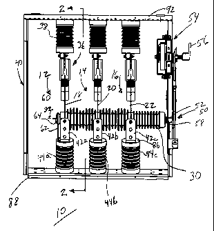
FIG. 1 is a front elevational view of a switch in accordance with the
principles of the
present invention;
FIG. 2 is a view, partly in section, taken generally along the line 2-2 of
FIG. 1; ~____

CA 02303531 2000-03-31
SC-5306-C
FIG. 3 is an elevational view of a bearing for an operating member of the
switch of FIGS.
1 and 2;
FIG. 4 is an enlarged view, partly in section, of portions of the switch of
FIG. I illustrating
the support of the operating member of the switch of FIGS. I and 2; and
FIG. 5 is a right-side elevational view of a support bracket for the bearing
and operating
member of the switch of FIGS. 1-4.
DETAILED DESCRIPTION
Referring now to FIGS. 1 and 2, a power distribution switch 10 in accordance
with the
present invention includes multiple switch poles, e.g. three switch-pole
assemblies 12, 14 and 16
as illustrated in the specific embodiment of FIG. 1. In this specific
illustrative embodiment, the
three switch-pole assemblies 12, 14 and 16 are operable between open and
closed positions via
pivotally mounted switch blades 18, 20 and 22 respectively, the closed
position being shown in
FIGS. I and 2, the open position shown in phantom in FIG. 2 at 18'. The switch
blades 18, 20
and 22 are carried by an operating member 30 that is mounted for pivotal
movement about an axis
32 that is substantially horizontal in the illustrative arrangement. Each of
the switch-pole
assemblies 12, 14 and 16 includes a stationary contact assembly 36 having arc-
extinguishing
capabilities in the specific embodiment where the switch 10 is a load-
interrupting switch. The
stationary contact assemblies 36 are each supported by an insulator 38 affixed
to a frame 40 of the
switch 10. The switch blades 18, 20 and 22 are each electrically connected to
a respective lower
contact termina142 via a sliding contact arrangement provided by lower contact
assemblies 43
(FIG. 2) carried by the lower contact terminal 42. The sliding contact feature
is also commonly
referred to as a wiping contact. The lower contact terminals 42 are supported
with respect to the
frame 40 at planar portions 45 (FIG. 2) via insulators 44, for example, lower
contact terminals 42
a, b and c supported by respective insulators 44a, b and c.
The operating member 30 is rotated via a linkage 50 that connects an operating
shaft 52 of
the operating member 30 to be driven by an operating mechanism 54. The
operating mechanism
54 is a stored energy device that is operated by a handle 56. The operating
member 30 is
rotatably mounted at a first end by the operating shaft 52 within a bearing
58. The opposite end
of the operating member 30 is pivotally supported at 60 via a support bracket
62 that is affixed to
the support insulator 44. In a specific embodiment, the support bracket 62 is
conductive. Thus,
in operation, the support bracket 62 is energized at the same potential as the
lower contact
termina142.
-2-

CA 02303531 2000-03-31
SC-5306-C
With additional reference to FIGS. 3-5, the operating member 30 includes a
cylindrical
bearing surface 64 (FIGS. 1 and 4) that is received within a bearing 66
carried within a circular
receiving opening 68 (FIG. 5) of the support bracket 62. The bearing 66 is of
split ring
construction (FIG. 3) and is retained within a circular receiving opening 68
of the support bracket
62 via the cooperation between a groove 70 and shoulders 72, 74 on the
perimeter of the bearing
66 and the rim 76 of the receiving opening 68 of the support bracket 62. In
this way, the bearing
66 is installed within the rim 76 of the receiving opening 68 and the inserted
operating member 30
in the vicinity of the cylindrical bearing surface 64 locks or retains the
operating member 30 and
the bearing 66 within the support bracket 62. In a specific embodiment, the
bearing 66 is
fabricated from molybdenum-impregnated nylon, while the operating member 30 is
fabricated
from cycloaliphatic epoxy resin. This combination has been found suitable to
accomplish the high
speed operation and support of the operating member 30 via the quick-make,
quick-break
operating mechanism 54 of the switch 10. In accordance with this
configuration, it has been
found possible to achieve a low ratio between the axial length 71 and the
diameter 73 of the
bearing 66, e.g. on the order of 1:6 as illustrated in FIGS. 3 and 4. This low
ratio is useful to
minimize the axial lengths of the bearing 66 and the cylindrical bearing
surface 64, the overall
length of the operating member 30, and the distance by which the operating
member 30 and the
support bracket 62 extend beyond the support insulator 44a, with resultant
economies of space
and component sizes.
It has been found desirable to mount the contact assemblies 43 so as to be
aligned along
the path between the center 32 of the operating member 30 and the base of the
support
insulators 44. In that way any movement of the insulators that may be caused
by extreme loading
results in movement of the contact assemblies 43 more nearly along the
circumferential
surface contact of the switch blades 18, 20 and 22. For example, different
mounting orientations
result in movement of the contact assemblies in a direction that tends to
separate the contact
assemblies from the switch blades 18, 20 and 22. In accordance with additional
aspects of the
present invention, the insulators 44 supporting the operating member 30 are
oriented such that
their longitudinal axes, e.g. 80, are aligned with respect to the radial axis
82 of the operating
member 30 as seen in FIG. 2 but not directly below the operating member 30.
This
orientation provides for preservation of space in the cable termination area,
generally referred to
at 84 beneath and to the rear of the lower contact terminals 42, while also
simplifying the
mounting of the lower contact terminals 42 and the lower contact assemblies 43
to the support
insulators 44. Specifically, this permits mounting of the planar portions 45
of the lower
contact terminals 42 and the lower contact assemblies 43 directly to an upper
planar surface 86 of
-3-

CA 02303531 2000-03-31
SC-5306-C
the support insulators 44 which simplifies the shape and fabrication of the
lower contact terminals
42 and the lower contact assemblies 43 and avoids the need for additional
parts to mount these
components. As seen in FIG. 2, a lower mounting member 88 of the frame 40, to
which the
lower planar surfaces 90 of the insulators 44 are mounted, is tilted or
inclined with respect to the
generally planar configuration of the switch 10 and the frame 40 and an upper
mounting member
92 of the frame 40 to which the upper support insulators 38 are mounted. The
generally planar
configuration of the switch 10 and the frame 40 are typically arranged
vertically for application
in metal-enclosed gear.
While there have been illustrated and described various embodiments of the
present
invention, it will be apparent that various changes and modifications will
occur to those skilled in
the art. Accordingly, it is intended in the appended claims to cover all such
changes and
modifications that fall within the true spirit and scope of the present
invention.
-4-

Representative Drawing
A single figure which represents the drawing illustrating the invention.
Administrative Status

2024-08-01:As part of the Next Generation Patents (NGP) transition, the Canadian Patents Database (CPD) now contains a more detailed Event History, which replicates the Event Log of our new back-office solution.

Please note that "Inactive:" events refers to events no longer in use in our new back-office solution.

For a clearer understanding of the status of the application/patent presented on this page, the site Disclaimer , as well as the definitions for Patent , Event History , Maintenance Fee  and Payment History  should be consulted.

Event History

Description Date
Inactive: COVID 19 - Reset Expiry Date of Patent to Original Date 2020-06-16
Inactive: COVID 19 - Deadline extended 2020-06-10
Inactive: COVID 19 - Deadline extended 2020-05-28
Inactive: COVID 19 - Deadline extended 2020-05-14
Inactive: COVID 19 - Deadline extended 2020-04-28
Inactive: Expired (new Act pat) 2020-03-31
Inactive: COVID 19 - Deadline extended 2020-03-29
Common Representative Appointed 2019-10-30
Grant by Issuance 2009-06-23
Inactive: Cover page published 2009-06-22
Pre-grant 2009-01-26
Inactive: Final fee received 2009-01-26
Notice of Allowance is Issued 2009-01-12
Letter Sent 2009-01-12
Notice of Allowance is Issued 2009-01-12
Inactive: Approved for allowance (AFA) 2008-10-03
Amendment Received - Voluntary Amendment 2008-01-04
Inactive: S.30(2) Rules - Examiner requisition 2007-07-20
Inactive: S.29 Rules - Examiner requisition 2007-07-20
Letter Sent 2005-02-02
Request for Examination Received 2005-01-13
Request for Examination Requirements Determined Compliant 2005-01-13
All Requirements for Examination Determined Compliant 2005-01-13
Inactive: Cover page published 2000-10-08
Application Published (Open to Public Inspection) 2000-10-08
Inactive: IPC removed 2000-06-02
Inactive: IPC assigned 2000-06-02
Inactive: IPC removed 2000-06-02
Inactive: First IPC assigned 2000-06-02
Inactive: IPC assigned 2000-06-02
Inactive: Filing certificate - No RFE (English) 2000-05-03
Filing Requirements Determined Compliant 2000-05-03
Letter Sent 2000-05-03
Application Received - Regular National 2000-05-02

Abandonment History

There is no abandonment history.

Maintenance Fee

The last payment was received on 2009-03-27

Note : If the full payment has not been received on or before the date indicated, a further fee may be required which may be one of the following

  • the reinstatement fee;
  • the late payment fee; or
  • additional fee to reverse deemed expiry.

Please refer to the CIPO Patent Fees web page to see all current fee amounts.

Owners on Record

Note: Records showing the ownership history in alphabetical order.

Current Owners on Record
S&C ELECTRIC COMPANY
Past Owners on Record
GINGER B. KAMBER
KEITH LACOUR
WALTER A. TYRJAN
Past Owners that do not appear in the "Owners on Record" listing will appear in other documentation within the application.
Documents

To view selected files, please enter reCAPTCHA code :


To view images, click a link in the Document Description column. To download the documents, select one or more checkboxes in the first column and then click the "Download Selected in PDF format (Zip Archive)" or the "Download Selected as Single PDF" button.

List of published and non-published patent-specific documents on the CPD .

If you have any difficulty accessing content, you can call the Client Service Centre at 1-866-997-1936 or send them an e-mail at CIPO Client Service Centre.


Document
Description 
Date
(yyyy-mm-dd) 
Number of pages   Size of Image (KB) 
Representative drawing 2000-10-02 1 18
Drawings 2000-03-31 3 82
Abstract 2000-03-31 1 15
Description 2000-03-31 4 207
Claims 2000-03-31 3 115
Cover Page 2000-10-02 1 44
Claims 2008-01-04 2 82
Representative drawing 2009-05-25 1 17
Cover Page 2009-05-25 2 49
Courtesy - Certificate of registration (related document(s)) 2000-05-03 1 113
Filing Certificate (English) 2000-05-03 1 163
Reminder of maintenance fee due 2001-12-03 1 112
Reminder - Request for Examination 2004-12-01 1 116
Acknowledgement of Request for Examination 2005-02-02 1 176
Commissioner's Notice - Application Found Allowable 2009-01-12 1 163
Correspondence 2009-01-26 1 42
Fees 2009-03-27 1 43