Note: Descriptions are shown in the official language in which they were submitted.
CA 02303629 2000-03-31
TITLE: DIFFERENTIAL DISPLACEMENT OPTICAL SENSOR - II
FIELD OF THE INVENTION
This invention relates to sensors for detecting
mechanical displacements. It is suited for use in machinery
of any type but, due to its high accuracy, is especially
suited to robotic applications and haptic controllers.
BACKGROUND TO THE INVENTION
It is known to provide a viewing surface that is
optically graded to vary in its transmissive or reflective
capacity along a longitudinal or circumferential path as part
of a position sensor. Sensors passing along such path are
exposed to varying illumination, corresponding to the location
of such sensors along the path.
A paper authored by V.D. Brown and W.S. Newman and
published by AT&T in the AT&T Technical Digest No. 78 of July
1986 (page 5) shows a "V" shaped light transmitting pattern
formed in a mask that is wrapped circumferentially around the
outer surface of a transparent cylinder source containing a
light source in its core. Rotation of the "V" shaped pattern
past a light sensor provides a sensor output that corresponds
to the rotational displacement of the cylinder.
CA 02303629 2000-03-31
2
This same publication depicts a tapering light-
transmitting region formed in a mask carried on the face of
a transparent rotatable disc or wheel. Light transmitted
through the disc to a sensor provides a sensor output which
is proportional to the rotational displacement of the
wheel.
In U.S. patent 5,666,236 of Bracken et al issued
to Iomega Corporation for a computer disc drive the
position of a read-head arm is determined by sensing a
"gray-scale" pattern, which includes an array of parallel
gradually thinning lines, based on the intensity of light
reflected from the pattern as it passes before a sensor.
Both of these prior art references rely upon
obtaining a light signal from a single optical source using
a single light modulating pattern and a single light
sensor.
Another reference, U.S. patent 5,153,472 to
Karidis et al depicts an actuator for positioning a probe
which includes as a position sensing device two oppositely
oriented, parallel, tapered windows (Figures 6, 6A; ref.
76, 77) mounted in a single plate. Light, optionally from
a common source shone through these triangular windows is
intercepted by two independent light sensors. By reason of
CA 02303629 2000-03-31
3
the reversed orientation of the two windows, the intensity
of light received by the respective sensor varies in a
complementary fashion. Without stating how the output
signals of the light sensors are processed, this reference
observes that this variable light limiting plate can be
used to determine its precise position.
While the prior art examples correlate position
with the intensity of light modulated by an optical
pattern, the full potential of such arrangements has not
been recognized or exploited.
Absent from these references is any suggestion
that the use of dual complementary images can serve to
reduce the noise and errors inherent in sensors of this
type. In particular, there is no suggestion as to the
advantageous ways in which such dual outputs may be
combined to produce measurement of improved fidelity and
precision. This invention addresses further improvements
in the utilization of this type of effect.
The invention in its general form will first be
described, and then its implementation in terms of specific
embodiments will be detailed with reference to the drawings
following hereafter. These embodiments are intended to
demonstrate the principle of the invention, and the manner
CA 02303629 2000-03-31
4
of its implementation. The invention in its broadest and
more specific forms will then be further described, and
defined, in each of the individual claims which conclude
this Specification.
SUMMARY OF THE INVENTION
The invention in one of its broader aspects
comprises a pair of complementary optical patterns of
graded optical reflection characteristics fixed
geometrically with respect to each other on a carrier
surface. The patterns are optically complementary to each
other in the sense that the optical characteristics of
fields of view at two paired sampling "window" regions
respectively positioned across each pattern and fixed with
respect to each other, provide values for the optical
characteristics of the two viewed patterns that, when the
difference between such values is taken, can be used to
provide a measure of improved accuracy for the displacement
of the complementary optical patterns and the carrier
surface beneath the two sampled window regions.
More particularly, the invention is based on a
position sensor supported on a frame for sensing the
CA 02303629 2000-03-31
position of a carrier surface that is displaceable with
respect to a sensor assembly comprising:
(a) dual optical patterns or images that provide
reflected light reflected from a source, the dual
5 optical patterns being positioned on and carried
by the carrier surface,
(b) displacement means whereby the carrier surface
and dual optical patterns are displaceable with
respect to the sensor assembly along a geometric
viewing path,
(c) the sensor assembly having dual light sensors for
providing output signals and positioned to
respectively receive reflected light from the
dual optical patterns from respective fields of
view encompassing portions of each of said
optical patterns as they are displaced with
respect to the sensor assembly along their
respective geometric viewing paths,
(d) difference measuring means coupled to said
sensors for providing a difference output based
on the output signals received from said sensors
wherein the dual optical patterns are optically graded and
are complementary to each other in their provision of
CA 02303629 2000-03-31
6
reflected light to said light sensors from said respective
fields of view whereby said difference output corresponds
to the position of the carrier surface with respect to the
sensor assembly. The extraction of the difference value as
generated by this arrangement allows common mode noise to
be rejected or attenuated.
A major source of noise in any sensor system is
that arising from the environment. This includes power
source noise and ambient light. All such noise can be
either eliminated or reduced by the use of a dual sensor
arrangement from which a differential signal is extracted.
This type of arrangement addresses what is known as
"common-mode" noise, or more precisely "correlated noise"
originating from a common source that typically has an
equal impact on the separate channels.
Preferably both fields of view receive light from
the same, common source of illumination. The invention
relies upon reflected light, preferably diffuse reflected
light, obtained from the optical pattern by reflection. In
the case of diffuse illumination, a surface area emits
photons generally from all over its entire surface. The
detected light of the invention in using diffuse light is
CA 02303629 2000-03-31
7
accordingly sampled from the entire surface area of the
sampled fields of view of the optical patterns.
By relying upon diffuse light less noise is
likely to be present in the sensor's output signal. This
is because most sources of specular light emit light that
is not of constant intensity over a significant surface
area. Thus if a sensor were viewing a specular source of
light through an opening in a mask, displacement of the
mask would not necessarily cause the sensor output to vary
directly and precisely with respect to the degree of
displacement. Further, light sensed directly from a
specular light source, e.g. an incandescent filament, is
more likely to contain photonic noise, e.g. shot noise,
than light sensed from a diffuse source.
The invention is based upon the optical patterns,
as detected through respective fields of view, having a
varying reflective capacity along the direction of their
displacement. Such optical patterns may be based on a
bright region formed against a black background; or the
field may be reversed to provide a dark shaped region
formed against a bright background.
The optical patterns suited for use in the
invention in linear displacement systems may be in the form
CA 02303629 2000-03-31
8
of two equal isosceles triangles, or portions thereof,
aligned to point in opposite directions with their axes of
symmetry being parallel to each other. In such case the
sensed regions would be based on sensor fields of view
spanning the respective triangles, transversely to their
axis of symmetry. The use of triangular images contributes
to providing an output that varies linearly with
displacement. Providing a linearly varying output is not,
however, essential when non-linearity may be accommodated
by appropriate adjustive signal processing. In fact,
linear output can also be provided through use of
complementary images that are not triangular: the image
widths may vary in accordance with curves created by second
and fourth order polynomials.
In another variant, the optical patterns in
rotational systems may be in the form of two crescent-
shaped wedges disposed about a centre of rotation for a
rotating carrier. The bifurcating centre lines of the
respective wedge patterns are preferably concentric about
the same centre of rotation. The sensed regions are then
selected to be within fields of view, conveniently window-
defined, that span the respective crescent-shaped patterns.
CA 02303629 2000-03-31
9
Such fields of view are preferably oriented in a radial
direction.
The crescent-shaped patterns may be mirror-image
shapes disposed symmetrically about the centre of rotation
at equal radial distances. Or they may be of differing
shapes and placed with one pattern nested within the other
within a sector of the rotatable carrier. In either case
the sensed region, as detected by respective sensor means
associated with each region, should provide values for
their respective optical characteristics that can, when a
difference value is extracted, cancel-out or minimize
common mode noise.
The optical pattern may be distinct, as in the
case of triangular patterns; or it may be diffuse, as in
the case of a "grey" state created by a field of micro-dots
of varying density. In all cases, the optical
characteristic of the sensed region must provide signals
that can exploit the difference criteria of the invention.
In the case of the use of distinct, complementary
optical patterns, such as triangles or crescent-shaped
wedges, the parameter measured within the sensed region is
the total value for the light received from the field of
view. The field of view in such case should preferably be
CA 02303629 2000-03-31
wide enough to span both opaque and illuminating portions
of the sensed region. In the case of triangular patterns,
that have a maximum width at one end the sensors should
preferably sample sensed regions through a field of view
5 that is as wide as the triangle at one end of the geometric
path being sampled.
In order to reduce noise, it is preferable that
a sensor in this type of system have as large field of view
as practical. This will increase the signal strength. The
10 preferred pattern is one that ranges from full intensity to
complete extinguishment over the limits of geometric
displacement of the image. Thus, if the range of
displacement is equal to the width of the field of view,
then a simple black-white boundary, positioned centrally
within the viewing path will produce the highest modulation
of output. This, in-turn, will tend to increase the
signal-to-noise ratio.
By providing an image which is geometric in shape
e.g. a triangle, the rate of change of illumination of the
sensor with displacement of the image can be decreased over
that of a black-white boundary. Further, the span of
travel that can be detected for the geometric image can be
enlarged indefinitely beyond the width of the viewing
CA 02303629 2000-03-31
11
window. The maximum displacement that can be measured
corresponds to the length of the "tapered" geometric
pattern, less the width of the viewing window.
While the sensed regions may be separated from
each other by substantial distances, an advantage of
placing the sensed regions in close proximity is that a
common light emitter may serve to provide identical or near
identical conditions of illumination at the respective
sensed regions.
Significant advantages of the invention arise
when dual complementary images are exposed under common
illumination conditions for viewing by dual matched sensors
through fields of view that provide similar, corresponding
illumination for each sensor from its respective image.
When the illumination conditions are identical, this will
eliminate or limit the need for a calibration component
that may arise when separate sources of illumination are
provided at separate locations. Illumination within the
fields of view for the two sensors need not be constant
across each field. But the benefits of the invention will
be obtained if similar conditions of illumination apply to
each of the viewed regions. By taking the difference
between the respective signals from the two sensors under
CA 02303629 2000-03-31
12
fully balanced conditions, common mode noise will be
eliminated.
Under practical circumstances the sensors may not
be perfectly matched and other constraints may be less than
ideal. But even in such cases, common mode noise will be
reduced. If the departures from ideal balance are known,
e.g. the ratio of the illuminations of the respective
images or mis-matches in the images, then corrective
procedures, such as increasing the value of the output from
one sensor before extracting the difference value, may be
applied to further decrease common mode noise. These
procedures can be part of a calibration process. The key
objective is to produce a differential value output that
varies with the displacement of a pair of viewed images of
complementary character past the fields of view of the
sensors.
A further means of reducing noise arises from the
photodiode circuitry electrical circuit arrangement for the
light sensors. Typically these sensors are solid-state,
light sensing diodes that are operated in their reverse
current range --photodiodes. Alternately, photo-
transistors may be employed.
CA 02303629 2000-03-31
13
A normal arrangement is to apply a reverse
voltage to a photodiode through a current limiting, biasing
resistor. As light falls on the light-sensing diode, the
reverse current increases. The change in the voltage drop
across the biasing resistor is typically taken as the
output signal that corresponds to the degree of
illumination.
If instead of sampling the voltage drop across
the current limiting resistor, if the voltage drop across
the diode is taken as the signal source, then a higher
signal-to-noise ratio may be achieved when the diode is
operated in its reverse region.
The foregoing summarizes the principal features
of the invention and some of its optional aspects. The
invention may be further understood by the description of
the preferred embodiments, in conjunction with the
drawings, which now follow.
SUMMARY OF THE FIGURES
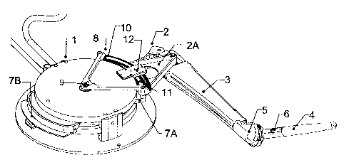
Figure 1 is a perspective view of a hand
controller incorporating a position sensor according to the
invention.
CA 02303629 2000-03-31
14
Figure 2 is an exploded perspective view of the
position sensor components of Figure 1.
Figure 3 is a cross-sectional view of the light
source and light detector components of the light sensing
assembly of Figure 2.
Figure 4 is a schematic view of the electrical
circuit associated with Figure 3.
Figures 5A, 5B are reversed field views of curved
images for use in a rotary sensor.
Figures 6A, 6B depict paired linear triangles on
reversed fields for use in a linear displacement sensor.
Figures 7A, 7B and 7C depict respectively one
half of a paired image for a triangular pattern, a quasi-
triangle based on parabolic or quadratic curvature, and a
non-linear image based upon fourth order curvature.
Figure 8 shows a linear displacement sensor image
with an abrupt black-white boundary that provides an
improved signal to noise ratio.
Figure 9 depicts dual, complementary gray-scale
graded images for use in a linear displacement sensor.
Figure 10 depicts mirror image circular counter
parts to dual triangular images for use in measuring up to
nearly 180 degrees of rotary displacement.
CA 02303629 2000-03-31
Figure 11 depicts the rotary counterpart to
Figure 8.
Figures 12A and 12B show respective rotary
counterparts to Figure 5A that span about 300 degrees and
5 180 degrees, with the crescent in Figure 12B truncated.
Figure 13 depicts a sensor assembly that moves on
a rotary linkage while detecting light reflected from a
geometric pattern carried on the stationary case of a
controller.
10 DESCRIPTION OF THE PREFERRED EMBODIMENT
Figure 1 shows a haptic hand controller 1 which,
in feed-back mode, drives an arm 3 through linkages 2 to
displace a handle 4 carried through a gimballed joint 5
which is grasped by a user. These same linkages provide a
15 position sensing system for the centre point of the
gimballed joint.
A series of torquers 7A, 7B drive the linkages 2.
Shown mounted to one of the linkages 2A is a rotational
position sensor 8 carried by a torquer 7A. This sensor 8
has a carrier surface 10 on which is located a geometric
pattern 11. This pattern 11 swings in an arc about a
CA 02303629 2000-03-31
16
central axis 9 with movement of the linkages 2, passing the
pattern beneath a light sensing assembly 12.
The light sensing assembly 12, as shown in
exploded view in Figure 2, has a light source 13 and two
light sensors 14A, 14B, preferably based on solid-state
photodiodes or photo-transistors. The source 13 and
sensors 14A, 14B are fitted into a mask 15 having two
windows 16A and 16B that provide the sensors 14A, 14B with
respective fields of view 17A, 17B of the geometric pattern
11 (shown in Figure 3).
The light source 13 is positioned to illuminate
the geometric pattern 11 in the regions of both of these
fields of view 17A, 17B at the same time and to a similar
degree. Preferably, the light source 13 is positioned to
provide equal illumination conditions within and over each
of the respective fields of view 17A, 17B. It is
acceptable, if the illumination has a gradient, for this
gradient to be similar or symmetrical within each of the
fields of view 17A, 17B.
A cover plate 18 seals-off the mask 15 containing
the light source 13 and photodiodes 14A, 14B within.
Conveniently, the cover plate 18 may also constitute a
substrate for printed circuit connections. Electrical
CA 02303629 2000-03-31
17
leads 19 as shown in Figure 3 protrude through holes in the
plate 18 to connect with wires (not shown) which may be
printed on cover 18.
The light sensing assembly 12 overlies the
optical pattern as shown in Figures 2 and 3 with the fields
of view 17A, 17B directed to complementary image portions
11A, 11B of the pattern 11 (Figure 4) . The field of
illumination of the light source 13 extends over the
greater portion of both fields of view 17A, 17B equally.
The complementary image portions 11A, 11B are shown in
Figure 4 as bright, preferably white, curved triangular
shapes on a dark, preferably black, background. An
optional curtain wall 31 may be provided to ensure that the
fields of view 17A, 17B are non-overlapping.
The mask 15 of the invention contributes several
valuable features to the invention. It helps define the
fields of view 17A, 17B more precisely by providing the
windows 16A, 16B. It provides a support for positioning
the light source 13 in precise relation to the light
sensors 14A, 14B to maximize the prospects that the field
of illumination provides similar illumination to the fields
of view 17A, 17B over the respective image portions 11A,
11B. And it serves to exclude or reduce to a minimum the
CA 02303629 2000-03-31
18
entry of ambient light into the fields of view 17A, 17B.
To achieve this last benefit, the mask is located directly
adjacent to the optical image 11 on the carrier 10.
In Figure 4 the circuitry of the signal
processing system is depicted. Signals issue from the
sensors 14A, 14B and are lead by wires 21A, 21B to a
difference amplifier 22 which provides a position signal 23
as its output. A power supply 24, biasing and limiting
resistors 25, 25A and filter capacitors 26 are of standard
form.
By extracting the signal for input to the
difference amplifier 22 from across the photodiodes 14A,
14B, an improved signal to noise ratio is obtained over
that which would arise if the voltage drop across the bias
resistors 25 were used as the input to the difference
amplifier 22.
Figure 5A and 5B show paired, curved, crescent
patterns 33 with reversed fields for sensing rotary
displacement. Figures 6A and 6B show paired straight
triangular patterns 32 with reversed fields for sensing
linear displacement. While the triangles 32 in each pair
of Figures 6A, 6B are of identical shape, the crescents 33
of Figures 5A, 5B differ so that the illumination values
CA 02303629 2000-03-31
19
extracted from fields of view 17A, 17B will support the
difference criterion of the invention.
While full triangles and figures are shown in
Figures 6A, 6B and 5A, 5B portion only of such figures may
also be employed.
Figures 7B and 7C in contrast with a normal
triangle of Figure 7A, are suitable images even though they
appear as distorted triangles 34, 35 that are "pinched"
inwardly with boundaries defined by quadratic and 4th order
polynomial curves. It has been found that complementary
geometric figures whose optical brightness varies as either
a second order or fourth order polynomial can be combined
in a difference amplifier to produce an output that varies
linearly with displacement over at least a portion of their
range. An advantage of using these geometric forms is that
the output signals from the sensors 14A,14B can be
maintained more nearly equal over a given range of
geometric displacement. Cancellation of correlated noise
is more effective in cases where the two signals from which
a difference is extracted are more nearly of equal value.
This is because some correlated noise is proportional to
signal strength.
CA 02303629 2000-03-31
A disadvantage of using geometric patterns of the
type identified in Figures 7B, 7C is that the alignment of
the respective images 34, 35 with their paired
complementary image and with the light sensing assembly 12
5 becomes more critical. A phase shift between the position
of two triangles 32 does not affect the difference output.
But such a phase shift becomes relevant for the other
geometric patterns.
Figure 8 shows two rectangular light-coloured
10 regions 27 on what is intended to be a black background 28.
This is a pattern that, when used with fields of view as
wide as the images, provides a maximum signal-to-noise
ratio but is limited in the span of linear displacement
that can be detected. By providing tapered images as in
15 Figures 5A, 6A, the span of displacement that can be
detected is increased.
The optical pattern being detected need not be a
distinct geometric figure. Figure 9 shows two grey-shaded
figures 29A, 29B that transition in a regular progression
20 from brightness to darkness.
The curved patterns 33 of Figures 5A 5B are
radially nested and are limited to detecting radial
displacements over a range of approximately 60 degrees. In
CA 02303629 2000-03-31
21
Figure 10 an alternate mirror-image optical image which has
image elements 30A, 30B is depicted. This image can be
used to measure radial displacements over a range of up to
nearly 180 degrees based on relatively narrow fields of
view 31A, 31B that extend radially in opposite directions.
The carrier 10 for this image would be a plate or disc that
is free to rotate through 180 degrees.
Figure 11 is the radial equivalent to Figure 8.
Its range is equal to the angular span of the relatively
large 170 degree maximum size windows 35 through which the
image is viewed. Two windows 35 are employed on opposite
sides of the center of rotation. The second window is not
visible in Figure 11 as it lies over the black region.
Smaller windows 35 may be employed, at the expense of
having the range of motion measurement limited to the span
of the windows using this configuration.
Figure 12A is the 300+ degree extension of Figure
5A and Figure 12B is the approximately 180 degree variant
on Figure 5A in which the crescent form has been truncated.
Both patterns are sensed through fields of view 17A, 17B.
While in the foregoing, the carrier surface 10
has been displaceable in space in respect to light sensors
14A, 14B that are fixed to a frame, in fact, the carrier
CA 02303629 2000-03-31
22
surface 10 need only be displaceable with respect to the
light sensors 14A, 14B. Thus, in Figure 13 a partial view
of a pivoting torquer arm 2A on a controller 1 is shown
wherein the light sensor assembly 12 is carried on the arm
3, and the geometric patterns 11 are fixed on the case of
the controller 1.
Dressing for wires is not shown in Figure 13, but
the disposition of electrical connection means in these
circumstances is a subject that is easily addressed by
those knowledgeable in the art.
The detection of the optical characteristic of
two sensed regions need not always require the presence of
two sensors. A single common sensor may receive signals
from both regions; and separate, controllable sources of
illumination may be provided for each individual sensed
region. The optical characteristics of the respective
regions is then provided by adjusting the intensity of
illuminations for both sources to provide a constant total
output at the receiving sensor; and by driving one or both
sources of illumination to cause their driving signals to
meet the sum and difference criteria of the invention.
For example, one source may be held at constant
illumination while the other is varied while geometric
CA 02303629 2000-03-31
23
displacement of the sensed regions is occurring to provide
a constant output at the sensor. An advantage of this
arrangement is that if the electrical signal driving the
source of illumination should vary linearly with the
illumination produced, then the sensor in such cases need
not itself respond linearly as it is intended to operate
with a constant value of illumination. However, as the
sensor is receiving illumination from two discrete sensed
regions, it should be positioned to ensure that any non-
linearities in its response characteristics are cancelled
out, e.g. it should be exposed equally over both regions.
CONCLUSION
The foregoing has constituted a description of
specific embodiments showing how the invention may be
applied and put into use. These embodiments are only
exemplary. The invention in its broadest, and more
specific aspects, is further described and defined in the
claims which now follow.
These claims, and the language used therein, are
to be understood in terms of the variants of the invention
which have been described. They are not to be restricted
to such variants, but are to be read as covering the full
CA 02303629 2000-03-31
24
scope of the invention as is implicit within the invention
and the disclosure that has been provided herein.