Language selection

Search

Patent 2304023 Summary

Third-party information liability

Some of the information on this Web page has been provided by external sources. The Government of Canada is not responsible for the accuracy, reliability or currency of the information supplied by external sources. Users wishing to rely upon this information should consult directly with the source of the information. Content provided by external sources is not subject to official languages, privacy and accessibility requirements.

Claims and Abstract availability

Any discrepancies in the text and image of the Claims and Abstract are due to differing posting times. Text of the Claims and Abstract are posted:

  • At the time the application is open to public inspection;
  • At the time of issue of the patent (grant).
(12) Patent Application: (11) CA 2304023
(54) English Title: SYSTEM FOR RECIRCULATING EXHAUST GAS IN AN INTERNAL COMBUSTION ENGINE
(54) French Title: DISPOSITIF POUR LE RECYCLAGE DES GAZ D'ECHAPPEMENT DANS UN MOTEUR A COMBUSTION INTERNE
Status: Deemed Abandoned and Beyond the Period of Reinstatement - Pending Response to Notice of Disregarded Communication
Bibliographic Data
(51) International Patent Classification (IPC):
  • F02M 26/12 (2016.01)
  • F02M 26/20 (2016.01)
  • F02M 26/32 (2016.01)
  • F02M 26/41 (2016.01)
  • F02M 26/44 (2016.01)
  • F02M 35/10 (2006.01)
(72) Inventors :
  • JESSBERGER, THOMAS (Germany)
(73) Owners :
  • FILTERWERK MANN & HUMMEL GMBH
(71) Applicants :
  • FILTERWERK MANN & HUMMEL GMBH (Germany)
(74) Agent: NORTON ROSE FULBRIGHT CANADA LLP/S.E.N.C.R.L., S.R.L.
(74) Associate agent:
(45) Issued:
(86) PCT Filing Date: 1998-09-12
(87) Open to Public Inspection: 1999-03-25
Availability of licence: N/A
Dedicated to the Public: N/A
(25) Language of filing: English

Patent Cooperation Treaty (PCT): Yes
(86) PCT Filing Number: PCT/EP1998/005820
(87) International Publication Number: EP1998005820
(85) National Entry: 2000-03-16

(30) Application Priority Data:
Application No. Country/Territory Date
197 40 584.3 (Germany) 1997-09-16

Abstracts

English Abstract


The invention relates to a system for recirculating exhaust gas in an internal
combustion engine. A connecting line (4; 10, 13; 26) for the recirculated
exhaust gas is connected to an intake pipe (2; 15; 22), cooling elements being
arranged in between. The cooling element may be e.g., a cooling channel (5;
18; 19; 25) for liquid coolant, integrated into the flange-type connection
joining the connecting line (4; 10, 13; 26) to the intake pipe (2; 15; 22), or
may be another heat conductive element.


French Abstract

L'invention concerne un dispositif pour le recyclage des gaz d'échappement dans un moteur à combustion interne, dispositif dans lequel une conduite de liaison (4; 10; 13; 26) destiné aux gaz d'échappement recyclés est rattaché à un tube d'aspiration (2; 15; 22), des éléments de refroidissement étant placés entre cette conduite et ce type d'aspiration. Un tel élément de refroidissement peut être, par exemple, un canal de refroidissement (5; 18; 19; 25) à liquide de refroidissement, qui est intégré au raccordement du typer bride reliant la conduite de liaison (4; 10, 13; 26) au tube d'aspiration, ou bien un autre élément thermoconducteur.

Claims

Note: Claims are shown in the official language in which they were submitted.

Claims
1. System for returning exhaust gas in an internal combustion engine, wherein
a connecting duct (4; 10, 13; 26) for the recycled exhaust gas is connected to
an air intake tube (2; 15; 22) with the interposition of cooling elements,
characterized in that the cooling element is a cooling channel (5; 18; 19; 25)
for liquid coolant, which is integrated into the flange-like connection of the
connecting duct (4; 10, 13; 26) to the air intake tube (2; 25; 22).
2. System according to claim 1, characterized in that the coolant liquid for
the
motor cooling is used as cooling liquid.
3. System according to claim 1 or 2, characterized in that the coolant channel
(5) is integrated into the air intake tube (2) made of plastic, the transition
of
the coolant channel (5) into the internal combustion engine being placed in
the cylinder head flange (1) of the motor and the interface being here sealed
with an additional gasket.
4. System according to claim 3, characterized in that a separate cooling line
is
placed in the flange between the exhaust pipe and the air intake pipe.
5. System according to any one of claims 1 to 4, characterized in that the
coolant channel is laid on a given length in or on the exhaust pipe.
6. System according to claim 5, characterized in that the coolant channel is
integrated into the exhaust pipe.
7. System for returning exhaust gas in an internal combustion engine wherein a
connecting line for the recycled exhaust gas is connected to an air intake
tube with the interposition of cooling elements, characterized in that the
cooling element is a massive, heat-conducting part (10; 21) which is at least
partially a component of the connecting line (10; 26) and is mounted on the
cylinder head (11; 24) in the area of the flange-like connection of the air
intake tube (15; 22).
8. System according to claim 7, characterized in that the means for fastening
the air intake tube (15) to the cylinder head (11) are at least partially used
as
6

means (16) for fastening the massive part.
9. System according to claim 7 or 8, characterized in that the manifold tube
for
the distribution of the recycled exhaust gas to a plurality of cylinders is
disposed in the massive part (10).
10. System according to any one of claims 7 to 9, characterized in that a
coolant
channel (18; 19) carrying coolant liquid runs in the cylinder head (11) or
also at least partially in the massive part (10).
11. System according to claim 7, characterized in that the massive
heat-conducting part is a tubular insert (21) in the air intake tube (22)
which is
placed with one end (23) against the cylinder head (24) with thermal contact,
and that the pipe-like connecting duct (26) is brought out through the wall of
the air intake tube (22) laterally on the insert (21).
12. System according to claim 11, characterized in that a free gap (27) is in
the
area where the connecting tube (26) is brought out in order to form a radial
distance away from the connecting tube (26).
13. System according to claim 11 or 12, characterized in that the end (23) of
the
insert (21) in contact with the cylinder head has an enlarged surface due to
expansion of the outside diameter.
7

Description

Note: Descriptions are shown in the official language in which they were submitted.


CA 02304023 2000-03-16
WO 99/14477 PCT/EP98/05820
System for Recirculating Exhaust Gas in an Internal Combustion Engine
State of the Art
The invention relates to a system for recycling exhaust gas in an internal
combustion engine according to the preamble of the principal claim.
In a system of this kind disclosed in DE 30 34 971 C2 exhaust gases of the
internal combustion engine are returned to the intake duct for the internal
combustion engine. The connecting duct is here embedded in a heat exchanger
for cooling the recycled exhaust gas through a broad range.
Taken in itself, it is also known that the recycled exhaust duct is fastened
by a
flange with two screws to the air intake tube made of plastic. In order to
insulate
the exhaust gas duct thermally from the air intake tube, mixture air is fed in
the
area of the flange by means of a diffuser tube. With this arrangement the
exhaust
gas temperature can be lowered in the area of the flange from about
450°C to
about 125°C at a recycling rate of about 20%.
Thermal peaks occur in such systems, especially in the areas of the gaskets,
made
of plastic as a rule, at the connection of the duct carrying the returned
exhaust gas
and in areas lying opposite the air entry opening. It is often difficult, due
to the
relatively small cross sections and relative long paths, to carry away
sufficient
heat. In many applications, in connection with direct injection motors, also
on
account of the exhaust gas return rate to be expected (up to 50%), there is
frequently a call for cylinder-selective introduction of the exhaust gas,
which
leads to additional thermal problems.
Statement of the Problem
The invention is addressed to the problem of improving a system of the kind
referred to above such that an optimum lowering of the temperature will be
possible.
Advantages of the Invention
The system of the invention is advantageously suitable, setting out from the

CA 02304023 2000-03-16
WO 99/14477 PCT/EP98/05820
generic kind, for solving the stated problem by the distinctive features of
the
principal claim. Owing to the fact that a cooling element in the form of a
cooling
channel for a liquid coolant is placed in a connecting duct for the recycled
gas,
which is integrated into the flange-like attachment of the duct connecting to
the
intake tube, the thermal stress on the plastic intake tube can be reduced at
high
recycling rates by simple means. Also the temperature of the aspirated air in
the
air intake tube can thereby be positively influenced.
In general, with the system according to the invention the thermal stress of
the
internal combustion engine, the exhaust temperature, the NOx emission and the
fuel consumption are reduced. If the motor coolant is used as the coolant, the
result is a simpler and less expensive construction.
The coolant duct can advantageously be integrated into the air intake tube,
which
as a rule is made of plastic, the transition from the cooling channel into the
internal combustion engine being situated in the cylinder head flange of the
motor, and the interface being sealed with an additional gasket. Alternatively
it
is also possible to place a separate coolant line into the flange between the
exhaust pipe and the air intake tube, or for the cooling passage also to be
placed
on a given length into or onto the exhaust pipe.
In another embodiment of the invention, the cooling element is a massive heat-
conducting part which is a component of the connecting line and is located on
the
cylinder head in the area of the flange-like connection of the air intake
tube. Due
to the massive attachment, of the manifold for the recycled exhaust, for
example,
to the cylinder head, the flowing gases can be cooled simply through the
cylinder
head flange which has cooling passages anyway.
Advantageously, the elements fastening the intake tube to the cylinder head
can
be used at least partially as means for fastening the massive part.
It is also advantageously possible to provide a cooling channel carrying
coolant
in the area of attachment of the massive part in the cylinder head or also at
least
partially in the massive part, whereby the cooling power can be further
optimized.
In another embodiment, the massive heat conducting part is a tubular insert
2

CA 02304023 2000-03-16
WO 99/14477 PCT/EP98/05820
which is integrated internally into the intake tube. This insert is in thermal
contact at one end with the cylinder head. With this arrangement, when the
intake tube is mounted to the cylinder head a good thermal transfer is easily
achieved between the insert, which is preferably made of metal, and the
cylinder
head. Through this heat transfer the thermal energy delivered,by the exhaust
gas
can be removed into the cooled cylinder head.
This heat transfer can also, if necessary, be increased if the end face of the
insert
in contact with the cylinder head has an expanded diameter.
The pipe-like connecting duct for the recycled exhaust is brought out through
the
wall of the intake tube on the side of the insert. The connecting duct and the
insert are joined together gas-tight, so that no gaskets are necessary between
the
connecting duct and the intake tube. The entering exhaust thus strikes against
the
inside wall of the cooled insert and therefore does not apply any elevated
thermal
stress to the plastic of the intake tube.
It is especially advantageous if in the area where the connecting duct is
brought
out there is a gap in the intake tube so as to form a radial space away from
the
connecting duct and thus to prevent any thermal stress on the intake tube in
this
area.
These and additional features of preferred embodiments of the invention will
be
found not only in the claims but also in the description and the drawings, the
individual features being applicable ipdividually or severally in the form of
subcombinations in the embodiment of the invention and in other fields and may
represent advantageous as well as independently patentable embodiments, for
which protection is hereby claimed.
The Drawings
Embodiments of a system of the invention for cooling recycled exhaust gas in
an
internal combustion engine will be explained with the aid of the drawings,
wherein:
Figure 1 is a schematic view of a cylinder head of the internal combustion
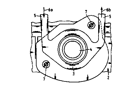
engine with a liquid-cooled connection of the recycled exhaust gas to
the intake tube.

CA 02304023 2000-03-16
WO 99/14477 PCT/EP98/05820
Figure 2 is a section through the connecting flange for the recycled exhaust
gas
with a cooling channel.
Figure 3 is a schematic view of a manifold tube for the recycled exhaust gas
with
a massive connection to the cylinder head.
Figure 4 is a section through the arrangement presented in Figure 3.
Figure 5 is a detail of a modified design of the system of Figures 3 and 4.
Figure 6 is a section through an embodiment with a heat-contacted insert, and
Figure 7 a detail of a modified design of the system of Figure 6.
Description of the Embodiments
In Figure 1 is shown a cylinder head 1 of an internal combustion engine with
the
parts which are important here. On an air intake tube 2 through which the air
reaches the combustion chambers of the internal combustion engine there is a
connection 3 for a manifold 4 through which the exhaust gas tapped from the
exhaust pipe is returned to the air intake tube 2. The exhaust gas in the
manifold 4
is at a high temperature due to the combustion in the motor, which can damage
the
intake tube and the adjacent units, since the latter are designed for normal
air
temperatures and are made mostly of plastic.
To the connecting flange 2 for the recycled gas a cooling duct 5 is connected
through which the coolant needed by the motor flows according to the arrows 6a
(in) and 6b (out). Figure 2 shows how this coolant duct passes around the
connecting flange 2 and thus around the manifold 4 bearing the recycled
exhaust
gas as shown in another view. The flange seen in Figure 2 is fastened to the
plastic intake tube 2 with two screws 7. The connecting tube 4 is introduced
into
the center of this flange.
In Figure 3 an embodiment is to be seen in which a manifold tube 10 for
recycled
exhaust gas is disposed on a cylinder block 11. In Figure 4 this arrangement
can
be seen in section. The recycled exhaust flows through the cross section 12 of
the
4

CA 02304023 2000-03-16
WO 99/14477 PCTBP98/05820
manifold 10 and is passed through pipes 13 and corresponding mounting flanges
14 into an air intake tube 15. To fasten the manifold 10 to the cylinder head,
bolt
holes 16, preferably already present, can be used for the intake tube,
possibly with
a metal sleeve 17.
In the cylinder block 11 in Figure 4 a coolant channel 18 is provided, through
which the coolant liquid flows. In an embodiment according to Figure 5 a
coolant
channel 19 can also be integrated at least partially into the manifold 10, in
which
case additional gaskets 20 are necessary.
In Figure 6 there is shown an embodiment which has a metal insert 21 placed in
the plastic intake tube 22 such that one end 23 is in thermal contact with the
cylinder head 24. In the cylinder head 24 there is also a coolant channel 25.
A
connecting tube 26 for the recycled exhaust gas is introduced laterally and
affixed
in a gas-tight manner. An open space 27 is here provided for the surrounding
plastic of the intake tube 22, since the relatively high temperatures of the
connecting tube must not harm the plastic of the intake tube 22.
The recycled exhaust gas flows according to arrows 28 into the relatively cool
insert 21 and strikes against it such that the thermal stress on the plastic
of the
intake tube does not become too great. To improve the cooling of the insert 21
still further, according to Figure 7 the area of the end 23 of the insert is
enlarged,
so that a still better thermal contact is achieved between the insert 21 and
the
cylinder head 24.

Representative Drawing
A single figure which represents the drawing illustrating the invention.
Administrative Status

2024-08-01:As part of the Next Generation Patents (NGP) transition, the Canadian Patents Database (CPD) now contains a more detailed Event History, which replicates the Event Log of our new back-office solution.

Please note that "Inactive:" events refers to events no longer in use in our new back-office solution.

For a clearer understanding of the status of the application/patent presented on this page, the site Disclaimer , as well as the definitions for Patent , Event History , Maintenance Fee  and Payment History  should be consulted.

Event History

Description Date
Inactive: IPC deactivated 2019-01-19
Inactive: First IPC assigned 2018-02-22
Inactive: IPC assigned 2018-02-22
Inactive: IPC expired 2016-01-01
Inactive: IPC from MCD 2006-03-12
Application Not Reinstated by Deadline 2003-09-12
Time Limit for Reversal Expired 2003-09-12
Deemed Abandoned - Failure to Respond to Maintenance Fee Notice 2002-09-12
Inactive: Cover page published 2000-06-08
Inactive: First IPC assigned 2000-06-06
Letter Sent 2000-06-02
Inactive: Courtesy letter - Evidence 2000-05-16
Inactive: Notice - National entry - No RFE 2000-05-10
Application Received - PCT 2000-05-08
Inactive: Single transfer 2000-04-27
Application Published (Open to Public Inspection) 1999-03-25

Abandonment History

Abandonment Date Reason Reinstatement Date
2002-09-12

Maintenance Fee

The last payment was received on 2001-08-14

Note : If the full payment has not been received on or before the date indicated, a further fee may be required which may be one of the following

  • the reinstatement fee;
  • the late payment fee; or
  • additional fee to reverse deemed expiry.

Patent fees are adjusted on the 1st of January every year. The amounts above are the current amounts if received by December 31 of the current year.
Please refer to the CIPO Patent Fees web page to see all current fee amounts.

Fee History

Fee Type Anniversary Year Due Date Paid Date
Basic national fee - standard 2000-03-16
Registration of a document 2000-04-27
MF (application, 2nd anniv.) - standard 02 2000-09-12 2000-09-12
MF (application, 3rd anniv.) - standard 03 2001-09-12 2001-08-14
Owners on Record

Note: Records showing the ownership history in alphabetical order.

Current Owners on Record
FILTERWERK MANN & HUMMEL GMBH
Past Owners on Record
THOMAS JESSBERGER
Past Owners that do not appear in the "Owners on Record" listing will appear in other documentation within the application.
Documents

To view selected files, please enter reCAPTCHA code :


To view images, click a link in the Document Description column. To download the documents, select one or more checkboxes in the first column and then click the "Download Selected in PDF format (Zip Archive)" or the "Download Selected as Single PDF" button.

List of published and non-published patent-specific documents on the CPD .

If you have any difficulty accessing content, you can call the Client Service Centre at 1-866-997-1936 or send them an e-mail at CIPO Client Service Centre.


Document
Description 
Date
(yyyy-mm-dd) 
Number of pages   Size of Image (KB) 
Representative drawing 2000-06-07 1 9
Abstract 2000-03-15 1 65
Description 2000-03-15 5 242
Claims 2000-03-15 2 80
Drawings 2000-03-15 5 120
Notice of National Entry 2000-05-09 1 193
Reminder of maintenance fee due 2000-05-14 1 111
Courtesy - Certificate of registration (related document(s)) 2000-06-01 1 114
Courtesy - Abandonment Letter (Maintenance Fee) 2002-10-09 1 179
Reminder - Request for Examination 2003-05-12 1 113
Correspondence 2000-05-08 1 15
PCT 1999-10-20 1 39
PCT 2000-03-15 17 651