Note: Descriptions are shown in the official language in which they were submitted.
CA 02304161 2000-03-22
WO 00/07351 PCT/JP99/03996
ADAPTER DEVICE AND NETWORK SYSTEM
s
Technical Field
The present invention relates to an adapter device for
transmitting an analog signal outputted from an electronic
device to a network, and a network system incorporating such
an adapter device.
Background Art
Console=type CPU systems including personal computers
for home use, TV game machines, and set-top boxes, which are
available in recent years, can be used while in communica-
tion with remote locations via telephone lines.
It is the general practice to connect such a console to
a network such as the Internet or the like with a cable via
an analog telephone line or a digital communication network.
For example, the console is connected by a modular cable to
an indoor modular hack that is connected to a network.
Recently, mobile telephone services including portable
telephone and PHS (Personal Handyphone system) as radio
telephone have been in widespread use. When the above con-
sole is connected to a radio telephone set, the console can
be connected to a network such as the Internet or the like.
In this case, the console is connected directly to the net-
work via the radio telephone set with an adapter such as a
dedicated modem, a connection adapter, or the like. Adap-
ters for use between radiotelephone sets and consoles in-
clude an adapter that incorporates a mobile telephone func-
CA 02304161 2000-03-22
WO 00/07351 PCT/JP99/03996
- 2 -
tion, as well as the dedicated modem and the connection
adapter. These adapters are usually available as options.
4
Heretofore, connecting a console to a network has posed
the following problems:
Since the console needs to be installed and used near
the modular jack, the console suffers a limitation on its
location.
It is tedious and time-consuming to connect the console
to the modular jack because a modular cable is required to
interconnect the console and the modular jack.
A TV game machine or a set-top box is normally used in
a certain fixed position, e.g., it is connected to a televi-
sion set in a living room. Therefore, a modular jack needs
to be installed near a TV game machine or a set-top box.
Portable telephone or PHS suffers other problems in
that it covers limited geographical regions only, cannot
pick up sufficiently strong radio waves in general residen-
tial areas other than municipal areas and outdoor environ-
meets, and cannot be used within buildings and condominiums.
The above problems have presented an obstacle to users'
efforts to connect consoles for home use to public networks.
Because of this obstacle, applications which use networks
have been prevented from becoming widely used.
It is therefore an object of the present invention to
provide an adapter device which is capable of promoting the
use of networks and making the use of a console valuable,
and a network system incorporating such an adapter device.
CA 02304161 2000-03-22
WO 00/07351 PGT/JP99/03996
- 3 -
Disclosure of Invention
The adapter device according to the present invention
is capable of transmitting an analog signal representative
of information from the console, which has been processed by
the transmission signal processing means, to the first tele-
phone set; and the first telephone set can output the infor-
mation from the console, which is obtained on the basis of
the received analog signal, to the public telephone line.
Therefore, the adapter device can utilize an existing analog
communication system which has generally been in widespread
use, making use of the communication system valuable.
The adapter device allows the console to be connected
to the public telephone line regardless of where the modular
hack is positioned, without concern over any cables, insofar
as the console is located at home. The adapter device can
be manufactured with ease.
In the network system according to the present inven-
tion, an adapter means can transmit an analog signal repre-
sentative of information from the console, which has been
processed by the transmission signal processing means of the
adapter means, to the first telephone set, and the first
telephone set can output the information from the console,
which is obtained on the basis of the received analog sig-
nal, to the public telephone line. Therefore, the network
system can utilize an existing analog communication system
which has generally been in widespread use, making use of
the communication system valuable.
Furthermore, the network system allows the console to
CA 02304161 2000-03-22
WO 00/07351 PGT/JP99/03996
- 4 -
be connected to the public telephone line regardless of
where the modular jack is positioned, without concern over ~
any cables, insofar as the console is located at home. The
adapter means can be manufactured with ease.
In the adapter device according to the present inven-
tion, a transmitting means can transmit an analog signal
representative of information from the console, which has
been processed by the transmission signal processing means,
to the receiving means, and the receiving means can output
the information from the console, which is obtained on the
basis of the received analog signal, to the public telephone
line.
Furthermore, the adapter device allows the console to
be connected to the public telephone line regardless of
where the modular jack is positioned, without concern over
any cables, insofar as the console is located at home. The
adapter device can be manufactured with ease.
Although certain preferred embodiments of the present
invention have been shown and described in detail, it should
be understood.that various changes and modifications may be
made therein without departing from the scope of the append-
ed claims.
The above and other objects, features, and advantages
of the present invention will become more apparent from the
following description when taken in conjunction with the ac-
companying drawings in which preferred embodiments of the
present invention are shown by way of example.
CA 02304161 2000-03-22
wo ooio~3si rc~rir~ro3s~ .
- 5 -
Brief Description of Drawings
FIG. 1 is a block diagram of a network system according
to the present invention, showing the manner in which sig-
nals are sent and received between a master device and an
adapter device;
FIG. 2 is a block diagram of an analog cordless tele-
phone system constructed on the basis of the network system
shown in FIG. 1;
FIG. 3 is a block diagram of a video entertainment sys-
tem as a console connected to the adapter device and a mas-
ter device, constructed on the basis of the network system
shown in FIG. 1;
FIG. 4 is a perspective view of the video entertainment
system and the master device shown in FIG. 3;
FIGS. 5 and 6 are a flowchart of a processing sequence
of the network system; and
FIG. 7 is a perspective view of a video entertainment
system as a console and an adapter device which is shaped to
match the video entertainment system.
Best Mode for Carrying Out the Invention
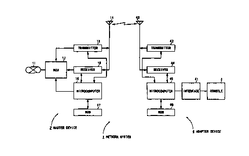
As shown in FIG. 1, a network system 1 according to the
present invention comprises a first telephone set (master
device) 2 connected to a public telephone line (public tele-
phone network) 11 by a cable, for transmitting and receiving
a radio analog signal representing desired information to
and from a second telephone set (slave device) 21 (see FIG.
2) with transmitting/receiving means 13, 14, 15, a console 3
CA 02304161 2000-03-22
WO 00/07351 PCT/JP99/03996 .
- 6 -
having a control means, and an adapter device 4 electrically
connected to the console 3.
The components of the network system 1 will be de-
scribed in detail below.
The first telephone set 2 is connected to the public
telephone network 11 by a cable with a modular jack or the
like, and serves as the master device. The second telephone
set 21 is capable of transmitting and receiving desired in-
formation as a radio signal to and from the master device 2,
and serves as the slave device.
The master device 2 comprises an NCU (Network Control
Unit) 12, a transmitter 13, an antenna 14, a receiver 15, a
microcomputer I6, and a ROM (Read-Only Memory) 17. The
transmitter 13, the antenna 14, and the receiver 15 jointly
make up a transmitting/receiving means.
The NCU 12 serves as a controller for connection to the
public telephone line 11, and controls signals as they are
inputted from and outputted to the public telephone line 11.
The transmitter 13 processes a signal which has been
inputted from a remote party through the NCU 12. The trans-
mitter 13 has a high-frequency transmission circuit, and
modulates a signal from a sender according to an analog
modulating. process.
The antenna 14 transmits and receives a radio signal to
and from the adapter device 4 or the slave device 21. For
example, the antenna 14 transmits a signal processed by the
transmitter 13 to the adapter device 4 or the slave device
21, and receives a signal transmitted from the adapter de-
CA 02304161 2000-03-22
WO 00/07351 PGT/JP99/03996 .
- 7 _
vice 4 or the slave device 21.
The receiver 15 processes a signal received by the an-
4
tenna 14, i.e., a signal transmitted from the adapter device
4 or the slave device 21.
The receiver 15 has a high-frequency reception circuit,
and demodulates a signal received by the antenna 14. For
example, the receiver 15 receives a modulated signal repre-
senting information from the console 3 via an antenna 43 of
the adapter device 4 and the antenna 14 of the master device
2, and demodulates the received signal to obtain the infor-
mation.
The signal (information) processed by the receiver I5
is outputted by the NCU 12 to the public telephone line 11.
The microcomputer 16 serves to control the components
of the master device 2, i.e., the NCU 12, the transmitter
13, and the receiver 15.
The ROM 17 serves as a memory means for storing various
items of information. For example, the ROM I7 stores pro-
grams for the microcomputer 16. The ROM 17 also stores a
slave device ID (identification) for identifying the slave
device 21 which is the second telephone set 21. Specifi-
cally, the slave device ID is used for the master device 2
to check the slave device 21 that has sent a communication
request to the master device 2.
The master device 2 of the above structure is able to
transmit and receive analog signals to and from the salve
device 21 and also to and from the adapter device 4 via
wireless links.
CA 02304161 2000-03-22
WO 00/07351 PCT/JP99/03996
- g -
The master device 2 is constructed as the master device
4
of an analog cordless telephone system for home use or a de-
vice equivalent thereto. Only the microcomputer 16 and the
ROM 17 are in the form of digital circuits, whereas the oth-
er components of the master device 2 are in the form of
analog circuits.
The master device 2 and the slave device 21 transmit
and receive analog signals of information therebetween ac-
cording to a given protocol. The adapter device 4 has a
plurality of protocols, and transmits and receives signals
to and from the master device 2 according to a selected one
of those protocols which matches the master device 2. Be-
cause the adapter device 4 has the plural protocols, it is
not limited to use with the master device 2, but is compati-
ble with a plurality of master devices having different pro-
tocols.
The slave device 21 which is the second telephone set
2I is constructed as shown in FIG. 2, for example. As shown
in FIG. 2, the slave device 21 comprises a key pad (operat-
ing part) 22, a microphone 23, a speaker 24, a display unit
25, a battery 26, a CPU 27, a transmission/reception signal
processor 28, and an antenna 29.
The key pad 22, which the user manually operates to en-
ter various control signals, has buttons "0" through "g",
"*", "#" as ten keys. When the key pad 22 is operated by
the user, the CPU 27 controls various components of the
slave device 21 according to control signals entered by the
user via the key pad 22.
CA 02304161 2000-03-22
WO 00/07351 PCT/JP99/03996
- g _
The microphone 23 detects a speech signal from the
user. A speech signal detected by the microphone 23 is
processed, e.g., modulated in an analog fashion, and then
transmitted to the master device 2.
The speaker 24 outputs a speech signal. Specifically,
the speaker 24 outputs a speech signal which has been input-
ted by a calling or called party to which the slave device
21 has been connected, and transmitted from the public tele-
phone line 11 via the master device 2.
The display unit 25 serves to display various items of
information. For example, the display unit 25 displays
items of information depending on control signals entered by
the user via the key pad 22, e.g., a telephone number.
The battery 26 supplies electric energy to the slave
device 21.
The transmission/reception signal processor 28 proc-
asses signals to be transmitted to the master device 2 via
the antenna 29, and also processes signals received from the
master device 2 via the antenna 29. The transmis-
sion/reception signal processor 28 has a high-frequency
transmission/reception circuit, and modulates and demodu-
lutes signals in an analog fashion.
The CPU 27 serves to control the components of the
slave device 21. For example, the CPU 27 controls the com-
ponents of the slave device 21, e.g., the display unit 25,
depending on control signals entered by the user via the key
pad 22.
The slave device 21 of the above structure is able to
CA 02304161 2000-03-22
WO 00/07351 PGT/JP99/03996 .
- 10 -
transmit and receive analog modulated signals to and from
the master device 2 according to a given protocol.
The master device 2 may be may comprise a power supply
31, a CPU 32, and a transmission/reception signal processor
33, as shown in FIG. 2. The transmission/
reception signal processor has the transmitter 13 and the
receiver 15 shown in FIG. 1, for example. The master device
2 is generally connected to the public telephone line 11 via
a cable with a modular jack 34.
The master device 2 and the slave device 21 jointly
make up a so-called analog cordless telephone system. The
adapter device 4 shown in FIG. 1 is added to and forms part
of the analog cordless telephone system thus constructed.
The adapter device 4 which allows the master device 2
and the console 3 to transmit and receive analog signals
representing desired information will be described below.
As shown in FIG. 1, the adapter device 4 has an inter-
face 41 as a connecting means for electrically connecting to
the console 3 which has a control means including a CPU
{Central Processing Unit), not shown, a transmitter 42 as a
transmission signal processing means for processing a signal
representative of information inputted from the console 3
via the interface 41, and an antenna 43 as a transmission
element for transmitting an analog signal generated by the
transmitter 42.
The adapter device 4 also has a receiver 44 for proc-
essing a signal transmitted from the master device 2 and re-
ceived by the antenna 43, a microcomputer 45 for controlling
CA 02304161 2000-03-22
WO 00/07351 PCT/JP99/03996 .
- 11 -
various components of the adapter device 4, and a ROM 46 as
4
a memory means for storing various data:
The interface 41 is electrically connected to the con-
sole 3 and transfers various items of information between
the console 3 and the adapter device 4.
The transmitter 42 processes a signal from the console
3 and transmits the processed signal via the antenna 43.
Specifically, the transmitter 42 has a high-frequency trans-
mission circuit, and modulates a signal from the console 3
according to an analog modulating process, and transmits the
modulated signal via the antenna 43. The transmitter 42 may
be of substantially the same construction as the transmis-
sion/reception signal processor 28 of the slave device 21.
Consequently, the adapter device 4 may be assembled using
the transmission/reception signal processor 28 as the trans-
mitter 42.
The antenna 43 serves to transmit and receive signals
to and from the master device 2.
The receiver 44 processes a signal received by the an-
tenna 43 and obtains information from the master device 2
based on the processed signal. The receiver 44 has a high-
frequency reception circuit, and demodulates a signal re-
ceived by the antenna 43 and obtains information from the
master device 2 based on the demodulated signal. The re-
ceiver 44 may also be of substantially the same construction
as the transmission/reception signal processor 28 of the
slave device 21. Thus, the adapter device 4 may be assem-
bled using the transmission/reception signal processor 28 as
CA 02304161 2000-03-22
WO 00/07351 PCT/JP99/03996
- 12 -
the receiver 44.
The microcomputer 45 serves to control the components
of the adapter device 4, i.e., the transmitter 42 and the
receiver 44.
4
The ROM 46 serves as a memory means for storing various
items of information. For example, the ROM 46 stores pro-
grams for the microcomputer 45.
The adapter device 4 thus constructed processes a sig-
nal representing desired information which have been gener-
ated by the console 3, e.g., modulates the signal in an
analog fashion, and transmits the processed signal to the
master device 2.
The master device 2 processes a signal transmitted from
the adapter device 4 in the same manner as it processes a
signal transmitted from the slave device 21. Specifically,
the master device 2 receives a signal transmitted from the
adapter device 4 and demodulates the received signal to ob-
twin information generated in the console 3 based on the
signal. The master device 2 outputs the signal from the
console 3 to the public telephone line 11 in the same manner
as it outputs a signal from the slave device 21.
In the adapter device 4 which is capable of transmit-
ting and receiving signals to and from the master device 2,
the microcomputer 45 and the ROM 46 are in the form of digi-
tai circuits, as with the master device 2. Other components
of the adapter device 4 than the microcomputer 45 and the
ROM 46 are in the form of analog circuits. The microcom-
puter 45 may be reduced in scale by giving the console 3
CA 02304161 2000-03-22
WO 00/07351 PCT/JP99/0399b
- 13 -
most of the functions which the adapter device 4 is to per-
form. '
The console 3 comprises a system having a CPU, such as
a personal computer for home use, a video game machine (TV
game machine) as a video entertainment system, or a set-top
box.
FIGS. 3 and 4 show the manner in which the adapter de-
vice 4 allows the console 3 to transmit an analog signal to
the master device 2 which is connected by a cable to the
public telephone line (public telephone network) 11.
The console 3 shown in FIGS. 3 and 4 is a video enter-
tainment system or video game system, and comprises a many
body 52 having a built-in CPU and a controller 53 as a manu-
al control means. The console 3 is energized by a power
supply 54. A display monitor 55 is connected to the main
body 52. The console 3 reads a program recorded in a re-
cording medium such as a CD-ROM (Compact Disk - ROM), not
shown, and executes a video game or the like based on the
program. The program may also be read into the main body 52
of the console 3 from the public telephone line I1 via the
master device 2 and the adapter device 4.
The display monitor 55 comprises a television set capa-
f
ble of receiving general television broadcasts. For this
reason, the display monitor 55 is often installed in a liv-
ing room.
The main body 52 serves to process data depending on
control signals entered via the controller 53 by the user.
The controller 53 comprises various buttons and a
CA 02304161 2000-03-22
WO 00/07351 PGT/JP99/03996
- 14 -
stick, and sends control signals to the main body 52 when
the buttons and the stick are manually operated by the user.
The display monitor 55 serves to display video images
of data that have been processed by the main body 52.
When the controller 53 is manually operated by the
user, the console 3 outputs various items of information to
the adapter device 4. For example, the user manually oper-
ates the controller 53 to generate information while viewing
video images displayed on the display monitor 55. The gen-
erated information is transmitted from the console 3 via the
adapter device 4 to the master device 2.
The adapter device 4 shown in FIG. 3 has a transmis-
sion/reception signal processor 51 for processing signals
transmitted and received between the adapter device 4 and
the master device 2. The transmission/reception signal
processor 51 comprises the transmitter 42 and the receiver
44 shown in FIG. 1.
The network system 1 is constructed as described above.
A process of transmitting and receiving data in the network
system 1 will be described below with reference to FIGS. 5
and 6. In the process, the slave device 21 requests the
master device 2 to establish a telephone circuit.
In step S1, the slave device 21 sends a connection re-
quest to the master device 2. In response to the connection
request, the master device 2 checks the slave device ID of
the requesting slave device 21 against a slave device ID
stored in the ROM 17 of the master device 2 in step S2. The
master device 2 checks the slave device ID of the requesting
CA 02304161 2000-03-22
WO 00/07351 PCT/JP99/03996
- 15 -
slave device 21 in order to decide whether the requesting
4
slave device 21 is permitted to be connected to the master
device 2 or not.
If the slave device ID of the requesting slave device
21 does not agree with the slave device ID in the ROM 17,
then the master device 2 does not permit the slave device 21
to be connected to the master device 2 in step S21.
If the slave device ID of the requesting slave device
21 agrees with the slave device ID in the ROM I7, then the
master device 2 checks whether the circuit of the analog
cordless telephone system is busy or not in step S3. The
circuit of the analog cordless telephone system is busy when
no secure connection has been made between the slave device
and the circuit or the circuit is being used by another
slave device.
If the circuit of the analog cordless telephone system
is busy in step S3, then the master device 2 carries out a
busy-circuit process in step 531. If the circuit of the
analog cordless telephone system is not busy, i.e., can be
used, than the master device 2 searches for an idle channel
in step S4. Specifically, the master device 2 searches for
an idle channel in a frequency band assigned to the analog
cordless telephone system.
If no idle channel is available in step S4, then the
master device 2 carries out a busy-channel process in step
S41.
If an idle channel is available in step S4, then the
master device 2 sets the idle channel as an active channel
CA 02304161 2000-03-22
WO 00/07351 PCT/JP99/03996
- 16 -
in step S5. The master device 2 can now communicate with
the slave device 21 in step S6.
4
In step S7, a telephone number entered in the slave de-
vice 21 by the user is transmitted to the master device 2.
The master device 2 then dials the transmitted telephone
number in step S8, and thereafter performs a connection
check in step S9. If the dialed telephone number is busy in
the connection check, then the master device 2 carries out a
busy process in step S91.
If the master device 2 is connected to the party of the
dialed telephone number in the connection check, then the
master device 2 establishes a link with the dialed party via
the public telephone line 11 in step S10.
Thereafter, information from the console 3 is transmit-
ted to the master device 2 by the adapter device 4. The in-
formation from the console 3 is therefore transmitted from
the master device 2 to the dialed party via the established
link.
For example, if the dialed party has a device with a
display unit, then the information from the console 3 is
displayed on the display unit.
For stopping the communication, the slave device 21
sends a disconnection request to the master device 2 in step
S12, and the link is disconnected in response to the discon-
nection request in step S13.
The network system 1 incorporating the adapter device 4
has been described above.
With the adapter device 4 added to the analog cordless
CA 02304161 2000-03-22
WO 00/07351 PCT/JP99/03996
- 17 -
telephone system, the network system l provides a communica-
tion system for communication with the console 3. There-
fore, if the adapter device 4 is added to an existing analog
cordless telephone system, then there is provided a communi-
cation system for communication with the console 3. A sys-
tem including the console 3 can easily be constructed becau-
se an existing infrastructure is employed.
The network system 1 allows the console 3 to be con-
nected to the public telephone line 11 through the adapter
device 4 and the master device 2 regardless of where the
modular jack 34 is positioned, without concern over any ca-
bles, insofar as the console 3 is located at home.
The components of the adapter device 4, other than the
microcomputer 45 and the ROM 46, are in the form of analog
circuits, and the microcomputer 45 may be reduced in scale
as most of the functions thereof can be performed by the
console 3. Therefore, the adapter device 4 can be con-
structed as a simple analog circuit, and does not require a
complex control circuit and an error-correcting circuit
which may be found in digital cordless telephone systems.
As a result, the adapter device 4 makes it possible to
provide an inexpensive communication system.
For the reasons described above, the network system 1
allows a network to be constructed at a low cost as it re-
quires no modem. The network system 1 will easily find
widespread use in view of the fact that the public telephone
line 11 has already been widely used. The adapter device 4
can easily be manufactured because it can be made of exist-
CA 02304161 2000-03-22
WO 00/07351 PCT/JP99/03996
- 18 -
ing units and components that are already present in large
quantities.
Even if the user does not have an analog cordless tele-
phone set, i.e., even if the user does not have the master
device 2, the user can construct a communication system con-
nected to the console 3 by using a reception adapter device
connected to the public telephone line ll.
Specifically, a reception adapter device for receiving
a signal from the adapter device 4 is provided, and the re-
ception adapter device comprises a reception element for re-
ceiving the signal from the adapter device 4 via a wireless
link, a reception signal processing means for processing an
analog signal received by the receiver to obtain information
from the console 3, and a connecting means connected to the
public telephone line 11 for outputting the information, ob-
tained by the reception signal processing means, from the
console 3 to the public telephone line 11.
The reception element comprises an antenna, for exam-
ple. The reception signal processing means comprises the
transmission/reception signal processor 33 of the master de-
vice 2 shown in FIG. 2, for example. The connecting means
comprises the NCU 12 of the master device 2 shown in FIG. 1,
for example.
Specifically, the reception adapter device may be iden-
tical in structure to a receiving means, provided in the
master device 2 connected to the public telephone line 11,
for transmitting and receiving an analog signal representa-
tive of information to and from the slave device 21 via a
CA 02304161 2000-03-22
WO 00/07351 PCT/JP99/03996
- 19 -
wireless link.
In the above modification, the reception adapter and
the adapter device 4 transfer analog signals from the con-
sole 3 according to a single protocol.
Accordingly, i~t is possible to transfer information
from the console 3 to the public telephone line 11 without
using the master device 2. A communication network can ea-
silt' and inexpensively be constructed by using the receiver
of the existing master device 2 as the reception adapter de-
vice.
The adapter device 4 may be shaped to match the console
3. For example, if the adapter device 4 is incorporated in
the video entertainment system shown in FIG. 4, then, as
shown in FIG. 7, the adapter device 4 may be constructed
such that it can be mounted on the back of the main body 52
of the video entertainment system in a substantially unitary
configuration. Since the adapter device 4 is mounted on the
back of the main body 52, the user no longer pays attention
to the fact that the adapter device 4 is mounted on the main
body 52, and can feel that the console 3, by itself, trans-
mits information via the master device 2 to the public tele-
phone line il.