Note: Descriptions are shown in the official language in which they were submitted.
CA 02304181 2004-08-10
METHODS AND APPARATUS FOR MONITORING
WATER PROCESS EQUIPMENT
s FIELD OF THE INVENTION
The present invention is directed to methods and apparatus for
monitoring industrial water process equipment. More particularly, the
invention is directed to the detection of teaks in water process equipment
to such as black liquor recover boilers.
BACKGROUND OF THE INVENTION
A boiler is an apparatus in which water or some other aqueous
is temperature control liquid to which makeup water is added and from
which blowdown is removed is vaporized into steam by the application of
heat from a furnace or heat-generating process system. In most
instances, the temperature control liquid is brought into close, indirect
contact with the process system to facilitate heat transfer. Leakage in a
boiler can result not only in contamination and fouling of the temperature
CA 02304181 2000-03-21
if::: i ~';;;D ., ll., 1L V- t'::.)( u.,.., f:::~
.. i '° f ; ' p i u,~. ' ~ ..;:
v 1...;; ; ..1~ ...c: .,l. a...;: ..: L .. . f
2
control liquid and the process system, but also in undesired physical
reactions. This is particularly true for the black liquor recovery boilers
used in many paper mills. In black liquor recovery boilers, the escape or
leakage of aqueous temperature control liquid from the so-called "water
s side" of the boiler into the hot, highly caustic "fire sideu can result in
violent explosions.
The prior art provides numerous techniques for monitoring and
controlling leaks in black liquor recovery boilers and other boiler systems.
io For example, U.S. Patent No. 5,320,967 (Avallone, et al.) discloses a
boiler system leak detection method that involves introducing an inert
tracer to the boiler in a known and uniform proportion to the feedwater,
sensing a characteristic of the tracer in the boiler at steady state,
converting the sensed characteristic to a value equivalent to the
1s concentration of the tracer in the temperature control liquid, and
activating a signal when there is excessive variance in the concentration
of the tracer. However, the method disclosed by Avallone, et al. is limited
by its requirement that the tracer be detected (sensed) when the boiler is
at steady state, which is said to occur only when there is no significant
2o change in any of five process parameters: the concentration of the tracer
in the boiler; the blowdown rate; the feedwater rate; the rate of feeding
tracer to the boiler; and the steaming rate in the absence of boiler
leakage.
25 Further limitations include the costs of tracer chemicals and
measuring equipment for both inputting tracer chemicals and for
analyzing blowdown.
CA 02304181 2000-03-21
li:::ir ~..." :.",:'. ~ :"~~ .,i, h..N., v" I; ~;; :.t?;:.t:
~:,." ",1~...~,~~~~.,~':,',a ., ..... . ,.", ..,
3
U. S. Pat. No. 5,363,693, Nevruz, teaches methods and apparatus
for detecting leakage from chemical recovery boiler systems. The
methods utilize measuring the mass input and output of a recovery boiler
and calculating the long and short term statistics for the drum balance of
s mass flow. From these calculations a t-test function is calculated to see if
both long term and short term moving average of drum balances are
significantly different, which in turn indicates whether a boiler leak is
occurring. Although this method provides corrections to sensor input
caused by flow sensor drift and offset, it still suffers from serious offsets
to in the leak detection signal during changes in process parameters,
namely steaming rate changes.
Consequently, there remains a need in the art for more flexible
leak detection methods which can be employed in boiler systems that are
is not at steady state, that is, where one or more process parameters is
subject to change.
SUMMARY OF THE INVENTION
2o The present invention provides for methods and apparatus for the
detection of leaks in boilers to which a temperature control liquid is added
and from which liquid is removed. In a preferred embodiment, the
temperature control liquid is supplemented with feedwater and this rate of
supplementation is measured. The temperature control liquid is also
2s removed as blowdown, main steam and sootblower steam, and these
rates of removal are also measured. The relationship between the water
input rate and the water output rate is determined based upon the rates
of supplementation and removal. In those boilers having attemperators,
CA 02304181 2004-08-10
4
this supplementation will include both addition from the attemperator and the
feedwater.
The offsets between the water input and output rates is determined and
corrected for. As such, the unaccounted for water rate can be determined
utilizing the known quantities of supplementation and removal. A comparison of
this derived amount with zero (i.e. the unaccounted for water rate is greater
than
0) indicates that a leak condition is present in the boiler.
In a broad aspect, then, the present invention relates to a method for
detecting a leak in a boiler having an automatic liquid level control
mechanism
in which a temperature control liquid in a containment means is supplemented
with feedwater and is removed as blowdown, main steam and sootblower steam
comprising the steps of: a) measuring a water input rate associated with said
feedwater supplementation to obtain data; b) measuring a water output rate
associated with said blowdown, main steam, and sootblower steam removal and
adding these rates to obtain data; c) determining the change of mass of said
temperature control liquid present in said containment means by taking the
derivative of said input rate with respect to time according to the formula:
dM/dt=a~dl/dt where: M=water mass contained; t=time; I=water input rate; and
a=a determinable constant where a is calculated using a least squares fit of
historical data of said boiler; d) determining the unaccounted for water rate
according to the formula: U=I-O-a~dl/dt where: U=unaccounted for water rate;
I=water input rate; O=water output rate; a=a determinable constant; and
dl/dt=the change in water input rate over time, t; e) comparing said
unaccounted
for water rate with zero; and f) indicating a leak condition if said
unaccounted for
water rite is greater than zero.
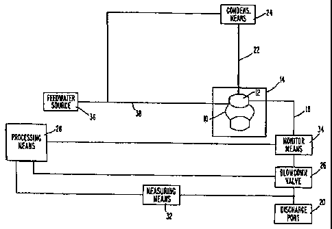
BRIEF DESCRIPTION OF THE DRAWINGS
The accompanying Fig. 1 is a schematic representation of a boiler
monitor system according to the invention.
CA 02304181 2004-08-10
4a
DETAILED DESCRIPTION OF THE INVENTION
The present invention provides for methods and apparatus for detecting
a leak in a boiler having an automatic liquid level control mechanism in which
a
temperature control liquid in a containment means is supplemented with
feedwater and is removed as blowdown, main steam, and sootblower steam
comprising the steps of:
a) measuring a rate associated with said feedwater supplementation
to obtain data;
b) measuring a rate associated with said blowdown, main steam, and
sootblower steam removal to obtain data;
CA 02304181 2000-03-21 _
:::n t.°,:. ...~1... . .;;, ~ iC~ t~ '.':~! . ..::.. ll..~.. IL".;(!
iY::l, ;i:;;~
~i...v. . i...i' .w.t. .:
c) correcting for the offsets between said supplementation
means and said removal means;
d) determining the unaccounted for water rate from the data
obtained in steps (a), (b) and (c);
e) comparing said unaccounted for water rate with zero;
indicating a leak condition if said unaccounted for water rate
io is greater than zero.
The present invention also provides an apparatus suitable for
indicating leaks in boilers. Apparatus according to the invention
comprise: measuring means in communication with feedwater
is supplementation means; measuring means in contact with blowdown,
sootblower steam and main steam removal means; correction means for
determining the offsets between the water input rate and the water output
rate based upon the rates of supplementation and removal; and
derivation means in communication with the measuring means for
zo deriving the unaccounted for water rate; and comparison means to
determine if a leak condition exists.
The methods and apparatus of the present invention can be used
to monitor virtually any type of equipment to which liquid is added and
2s from which liquid is removed and uses an automatic water level control
mechanism. The methods and apparatus of the invention preferably are
used to monitor and detect leaks in boilers, especially black liquor
CA 02304181 2004-08-10
recovery boilers. Representative boilers are disclosed by U.S. Patent
Nos. 3,447,895, Nelson et al.; 4,462,319, Larson; 4,498,333,
Parthasarathy; and 4,502,322, Tero.
s An exemplary monitoring system according to the invention is
shown in Figure 1, wherein a first "water side" containment means a
°boiler~ 10 containing temperature control liquid 12 is adjacent to and
in
thermal communication with a second "fire side" containment means 14
that typically contains hot vapors and a molten smelt bed. Boiler 10 is in
is fluid communication with blowdown line 18 for the discharge of blowdown
to discharge port 20 and with steam line 22 for the discharge of steam to
condensation means 24. The discharge of blowdown is controlled
through actuation of blowdown value 26, which can be operated manually
or under the control of an external computer or some other processing
is means (not shown). It is not necessary that the blowdown valve be under
control of or monitored by the system of the invention. Between boiler 10
and valve 26, blowdown line 18 is in fluid communication with monitoring
means 34 to provide information on the blowdown flow rate. Measuring
means 32 and 34, in turn, are in electrical communication with processing
2o means 28. Boiler 10 is also in fluid communication with feedwater source
36 via feed line 38.
During normal operation, the controlled addition of feedwater to
boiler 10 compensates for the removal of blowdown and steam, and
2s maintains a desired volume of temperature control liquid 12 within boiler
10. A natural consequence of steam generation in a boiler is a
CA 02304181 2000-03-21
it.. ~~;'~~ : .1; r..l[., il~ ~~ A,::U ~i:~):
.... ~ni .; ' L..P ....., ~ ~;s: .. ...i...
7
concentrating of incoming, non-volatile components. To control this
"cycling up" effect, one or more volumes of the relatively-concentrated
temperature control liquid typically are removed from the boiler as
blowdown and corresponding volumes of relatively-dilute feedwater is
s added. In accordance with the present invention, the blowdown is
measured at regular or irregular intervals or is continuously monitored to
determine the weight of water removed as blowdown.
The methods of the present invention are particularly effective for
io those containment means having an automatic water level control
mechanism. These mechanisms are found in boilers and function by way
of sensing a change in the amount of volume of water present in the
boiler. As water exits the boiler, the sensor indicates that the water level
has dropped and signals such so that it may be automatically
is replenished.
In boiler systems having an automatic water level control
mechanism, coefficients a, b and c can be calculated using a least
squares fit on historical boiler data. This °historical° data
can be that
2o gathered for roughly one month prior to applying the methods and
apparatus of the present invention. The least squares fitting is a widely
used mechanism for extracting meaning from a set of related
observations. In the instance of a boiler, a, b and c can be calculated
from an observation and gathering of liquid flow data into and out of the
2s boiler using a least squares fit mechanism. This gathering of data also
fits with the steps of the present invention as to the various rates
CA 02304181 2000-03-21
;~,1! 6::Mc ..~ °i" i'.,,,. s1 ~1~ a::°; ~C:1I
....I .",;;a~ . ~ , . ", .:,s. .,
8
measured. The coefficients a, b and c are particular to each boiler and
will even vary from different boilers of the same model and manufacture.
The fundamental equation for water mass balance in a
s containment means, such as a boiler, is:
dM = I-0-U
dt
io where:
M = Water mass contained
I - Water input rate (as feedwater)
O = Water output rate (as blowdown, main steam and sootblower stem)
U = Unaccounted water rate (as leak)
is t - Time
In an ideal situation, if water mass contained is not changed and
there is no unaccounted water rate (dM/dt and U both equal zero), then
the water input rate should equal the water output rate (I = O). However,
2o due to calibration mismatch between meters, the relationship between I
and O is generally in the form of
I=a*O+c (2)
2s where a and c are determinable constants or boiler dependent
parameters. The importance of a and c is to correct the calibration
mismatch while avoiding having to perform traditional calibration
techniques. Instead of calibrating each individual meter periodically, the
easier task of recalculating a and c need only be performed.
CA 02304181 2000-03-21
I)::7~ ~~"," ,.,ll"," ,~yl",p ;~:::I; ~~:,P ;::;~~ , ,..I~,. ~L.~. ~I::;I~
~~;::I; ~I:;;~I
9
Incorporating these terms into the calculation, the water mass
balance equation is
dM =I-a*O-c-U (3)
dt
Since I and O are measurable, to calculate U, dMldt must be
calculated. In boiler systems having an automatic water level control
mechanism, by observation, dMldt is proportional to dlldt, or
io
dMldt = b * dlldt (4)
where b is a determinable constant, like a and c, which can be calculated
using a least square fit on historical boiler data, for example, one month's
is worth of data. The importance of the b term in computing dMldt is in
eliminating the time lag between the input (I) and the output (O).
Combining equations (3) and (4) yields the following relationships:
2o U=I-a*O-b* dl-c (5)
dt
!f the unaccounted water rate (U) is greater than zero (within a
statistically-significant variance), a leak condition is indicated. Thus if U
2s is a positive number, then the boiler operator initiates an investigation
into the possible causes. This typically involves physical andlor
acoustical examination of the boiler and, depending on the magnitude of
the variance, complete shutdown of the boiler.
3o Mathematically, V(i), the value of any variable V at the ith data
point, can be written as:
CA 02304181 2000-03-21
n:, .c~ ~ y ~:l' .. .~ ~ . i;..y.. n:.;l~ '!:::i: a ~~;
..... ,
m
V(i) = V(i-1 ) + (V(i) - V(i-1 )) = V (i-1 ) +1 * dV i (6)
dt
Similarly,
s V(i) = V(i-2) + (V(i) - V(i-1 )) + (V(i-1 ) - V (i-2))
V(i-2) +2 * dV~, Etc.
dt
In General,
1o V(i) ~ V(i-b) +b * dV i (
dt
or
V(i) - b * dVji~ ~ V(i-b) (9)
dt
is Thus, Formula (5) at iteration (i) becomes
U (i) = I (i-b) -a * O(i) -c (10)
The term from equation (5), b * dl ,
dt
2o is designed to eliminate the time lag between the Input Rate (I) and the
Output Rate(O). By applying formula (9) to this term and equation, an
improved means for calculating and determining the presence of a leak is
realized. This improvement greatly increases the signal to noise ratio in
detecting leaks. Thus, correction for the offsets can be for the time index
2s andlor the magnitude of flow signals.
The improvement can be determined by the following calculations.
To simplify the calculation, there are five assumptions: 1 ) no leak is
present; 2) without load swing, both input (I) and output (O) are random
3o variables and they are not correlated; 3) both I and O have same noise
CA 02304181 2000-03-21
~.::r ~r~~, ..~~.~ ~r,.-.v i;.".:C ~i'w ~ n
...., . '~~ h ..r ....1. , ..., ~ ~t ~..~... d:.~ ,.., ~.;,
.. a..,.. .. ". . .:;1. ".h
11
level, i.e., both their Stdev = a; 4) since a is close to 1, a is presumed as
1; and 5) c is 0 since it will not affect noise level.
Accordingly, statistically, Formula (5) can be written as:
s Noise 1 (i) = I (i) -0(i) -b * (1(i) -I(i-1 )) _
(1-b) * I(i) + b* I(i-1 ) - O(i) (11 )
to
and Formula (10) as
Noise 2(i) = I(i-b) -O(i) (12)
By the above stated assumptions and standard calculations:
a - (1-b) 6 +b2az+a2= 2~-2-*b+2*b2*a
Noise 1
is - 1-b+b2 * ~* a (13)
and
a - az+a2 =~2*a (14)
Noise 2
20 This means that a is about the size of sqr (1-b+bz) times
Noise 1
a . A typical value for b is -3. As such, a is about the size
Noise 2 Noise 1
of 3.5a
Noise 2
At run time, since future data cannot be used and b is usually not
3o an integer, Formula (10) is modified to:
CA 02304181 2000-03-21
°°' w,..~ '"~,..;: ;;;a' ~~~~k ~:.;' .v'A,'I k.,~.~~:;II ~:.:~:
~~::~~
12
U(now) = a * I(Now) + (i * I(Now-1 ) -
a * 0(NowJy) -C (15)
where:
s ~3 = b - Floor(b)
«=1-p
Y = abs (Floor(b))
So if b = -3.7, then
to (i = b - Floor(b)= -3.7 - Floor (-3.7) _ -3.7 - (-4) = 0.3
a=1-a=1 -0.3=0.7 and
y = abs (Floor(b)) = abs (Floor (-3.7)) _
abs (-4) = 4
is Examples
zs
Data was gathered at a northeastern industrial boiler over a 50
hour period. During this period, feed water rate, steam rate and
blowdown were measured.
Using a least squares fitting of the historical data gathered before
this 50-hour period, the steam load swing parameter, b, and the
parameters for corrections for flowmeter calibration mismatch, a and c,
were calculated. These values were: a = 0.89, b = -4, and c = -2.
When employing equation (1 ), the severe load swing of this boiler
made it appear that at the time of the load swing that a leak was present.
However, after the load swing, the use of equation (1 ) indicated that the
CA 02304181 2000-03-21
~i:::~~ ('...,; ~..~.",,,.v li,..n :::;;i; c,:,l; i!'v!~ , ~ ~ ,;t. G..~..!r1;
iy;;i: 'i:r.
13
apparent "leak" had disappeared. Application of the above detailed
methods with the calculated boiler-dependent parameters, a, b and c,
indicated no leak was present. The methods of the present invention
provided greater accuracy than the traditional approach.
s
While this invention has been described with respect to particular
embodiments thereof, it is apparent that numerous other forms and
modification of this invention will be obvious to those skilled in the art.
The appended claims and this invention generally should be construed to
to cover all such obvious forms and modifications which are within the true
spirit and scope of the present invention.
sr