Note: Descriptions are shown in the official language in which they were submitted.
y CA 02305015 2000-04-12
PATENT
ATTORNEY DOCKET NO. 56.0533
INVENTORS: Edward K. Leugemors
William R. McIntire
MIXING METHOD AND APPARATUS
BACKGROUND OF THE INVENTION
Field of the Invention
This invention relates to high speed mixing. In particular, the invention
relates to
apparatus and methods for mixing oilfield cement slurnes at high rates for
cementing
wellbores.
Description of the Prior Art
The cementing of wellbores for land based and offshore oil and gas operations
requires a reliable and homogenous source of cement. Dry cement typically is
delivered
to a wellsite, provided to a cement mixer, combined with water in the mixer,
and pumped
downhole to solidify in a wellbore. In many cases, the slurry is recirculated
within the
mixing apparatus prior to pumping the mixture downhole.
Mixing and pumping cement at a high rate of speed is desirable to conduct
service
operations as quickly and efficiently as possible, so that the well can be
placed on line for
oil and gas production. If cement is mixed and pumped faster, substantial
savings are
achieved. Problems with cementing occur when cement builds up or cakes in the
interior
of the mixer. Such build-up of partially wet cement can become a hard and
relatively
impermeable mass -- blocking the flow of dry cement into the mixer. In such
cases, this
blockage undesirably reduces overall dry cement flow rate, thereby reducing
the overall
cement slurry output rate.
1
CA 02305015 2000-04-12
PATENT
ATTORNEY DOCKET NO. 56.0533
INVENTORS: Edward K. Leugemors
William R. McIntire
Jet mixers for combining dry cement with a liquid use the power in a liquid
jet to
entrain and mix the dry cement with liquid. Air inherent in the dry cement is
separated
from the resulting cement and liquid slurry, and the slurry usually is pumped
down oil or
gas wells to cement casing in place. The liquid may be water, cement slurry re-
circulated
through the mixing system, or other desired liquid. In the past, oilfield
cement jet mixing
has been accomplished primarily using straight jets sprays, that is, using a
spray that has
margins that are roughly parallel.
Generally, there are two rate limitations for jet mixers. First, there is an
initial
mixing rate limitation based upon the size and velocity of the liquid jet and
the geometry
of the mixer system. Second, there is a rate limitation that occurs when the
mixing area
becomes partially filled or blocked with a buildup of partially wetted, dry
cement
adhering to walls of the mixer.
When mixing commences, the initial mixing rate usually is the maximum
achievable rate. As mixing continues with prior art mixers, liquid from the
jet may
undesirably splash back and wet the inside surfaces of the mixer. As dry
cement enters
the mixer, the cement contacts and adheres to the wetted surfaces inside the
mixer and
accumulates, thereby restricting or blocking the passage of cement to the
fluid stream.
A significant portion of such splash-back is caused by air re-circulation
within the
mixer. When the jet slows in the gun barrel, the pressure in the barrel is
higher relative to
the mixing zone, and air recirculates back to the lower pressure in the mixing
zone. In
prior art devices, this recirculating air carnes slurry back to the mixing
zone where it wets
the walls. Build-up of materials within the mixing area of the unit eventually
results from
2
CA 02305015 2000-04-12
PATENT
ATTORNEY DOCKET NO. 56.0533
INVENTORS: Edward K. Leugemors
William R. McInrire
the blowback of the slurry into the mixing zone. This build-up restricts the
flow of fresh
cement into the mixer and reduces the achievable mix rate. Better eduction of
dry cement
and air in the mixing zone lowers the pressure, and reduces air recirculation
and
splashback of liquid or blowback of slurry, thereby reducing potential
material build-up.
Build-up of partially wetted material in the mixer is particularly detrimental
in
oilfield cementing applications. The oilfield mixing process is typically a
continuous
mixing process. To clean build-up from the mixer requires interrupting the
mixing
process and delaying the cementing application. Furthermore, oilfield
cementing rates are
typically much higher than powder mixing rates in other industries leading to
more rapid
build-up accumulation. Thus, it is important that mixing occur efficiently at
high rates.
These facts make it even more critical that mixing occur at high rates in an
efficient
manner.
What is needed is an apparatus and method of cementing that facilitates a high
rate of cement mixing with reduced build-up of material within the mixer. A
cement
mixer design reduces air recirculation or blowback of slurry from the slurry
stream back
into the mixer is highly desirable. Reducing build-up of material within the
mixer
reduces the time and cost required for cementing operations.
SUMMARY OF THE INVENTION
The invention comprises an apparatus and a method for mixing a particulate
composition with a liquid. In many cases, the liquid is an aqueous solution
containing
water. The apparatus comprises a spray nozzle, the nozzle being capable of
forcing a
liquid stream into close contact with a particulate composition. Also provided
is a
3
CA 02305015 2004-04-06
78703-1
mixing zone, wherein the particulate composition contacts
the liquid stream combining to form a slurry. Further, a
barrel is included having a proximal end and a distal end,
the proximal end of the barrel being in liquid communication
with the mixing zone, wherein the blowback of slurry from
the barrel to the mixing zone is reduced. In normal
operations, the slurry proceeds from the proximal end of the
barrel to the distal end of the barrel.
In one embodiment, the barrel diverges from a
smaller diameter at its proximal end to a larger diameter at
its distal end and contains an insert to restrict slurry
blowback to the mixing zone. In another embodiment, the
liquid stream exits the nozzle in a diverging pattern as it
passes along the interior of the barrel. In another
embodiment, the barrel diverges and the liquid stream exits
the nozzle in a diverging pattern.
In another embodiment, the liquid stream contacts
the full inner perimeter of the barrel near the distal end
of the barrel then the proximate end.
In another embodiment, said liquid stream is cone-
shaped.
In a further embodiment, the liquid stream
comprises recirculated slurry.
In another embodiment, water exits a water line in
an annulus surrounding the nozzle from which the liquid
stream exits in a diverging pattern.
A method of mixing cement is disclosed in which a
mixing apparatus is provided, the apparatus having a nozzle,
a mixing zone and a barrel. The nozzle typically is
oriented to emit a liquid stream into the mixing zone, the
4
CA 02305015 2004-04-06
78703-1
mixing zone being in liquid communication with the barrel.
The mixing zone further includes an input for dry cement.
During operation, liquid flows through the nozzle and mixes
with the dry cement to form cement slurry. Then, the cement
slurry is delivered into the barrel.
In accordance with one aspect of the present
invention there is provided an apparatus for mixing a
particulate composition with a liquid, comprising: (a) a
nozzle for providing a liquid stream in contact with a
particulate composition, (b) a mixing zone where said
particulate composition contacts said liquid stream and
particulate composition and liquid stream combine to form a
slurry, and (c) a diverging barrel having a proximal end and
a distal end, the proximal end of the barrel being in
communication with the mixing zone, wherein the slurry
proceeds from the proximal end of the barrel to the distal
end of the barrel, (d) wherein said liquid stream diverges.
In accordance with a further embodiment of the
present invention there is provided an apparatus wherein the
liquid stream contacts the full inner perimeter of the
barrel near the distal end of the barrel then the proximate
end.
In accordance with yet a further embodiment of the
present invention there is provided an apparatus wherein
said diverging liquid stream is cone-shaped.
In accordance with yet a further embodiment of the
present invention there is provided an apparatus wherein the
liquid stream comprises recirculated slurry.
4a
CA 02305015 2000-04-12
PATENT
ATTORNEY DOCKET NO. 56.0533
INVENTORS: Edward K. Leugemors
William R. McIntire
BRIEF DESCRIPTION OF THE DRAWINGS
The following Figures are provided to further illustrate the invention:
Figure 1 depicts a prior art configuration in which a non-diverging barrel
design
undesirably results in cement slurry build-up or caking within the interior of
the mixer;
Figure 2 depicts a prior art configuration in which interaction of a straight
liquid
stream with the barrel walls undesirably results in re-circulation of air.
Figure 3 shows one aspect of the current invention including non-diverging
fluid
stream with an insert to restrict blowback to the mixing zone;
Figure 4 is one aspect of the invention using a diverging liquid stream to
educt the
cement/air mixture;
Figure 5 shows another embodiment of the present invention showing a change in
the shape of the interior of the mixer at the junction of the mixing bowl and
barrel, which
suppresses air recirculation;
Figure 6 depicts another embodiment of the invention including a diverging
barrel
and a diverging liquid stream; and
Figure 7 depicts a preferred embodiment of the invention including a diverging
barrel, a diverging liquid stream and addition of water to the annulus
surrounding the
liquid stream.
DETAILED DESCRIPTION OF THE
PREFERRED EMBODIMENTS
A prior art mixing device 10 is shown in Figure 1. The device shown in Figure
1
is similar to current mixer designs in use today, such as for example the
CPS361
5
CA 02305015 2000-04-12
PATENT
ATTORNEY DOCKET NO. 56.0533
INVENTORS: Edward K. Leugemors
William R. McIntire
Caterpillar CBS393 "Slurry Chief' mixer (Slurry Chief is a trademark of the
Schlumberger Technology Corporation). In Figure 1, the prior art device 10 has
a nozzle
13 that emits a stream into mixing zone 14. Slurry spray 15 proceeds long the
converging
barrel 16 where it exits the unit. Slurry spray 15 is shown in Figure 1 with
no divergence
due to interaction with the interior walls of barrel 16. The upper bounds of
the slurry
spray 17 can emit blowback of air and splashback of slurry along pathways 18
in reverse
direction. This undesirable blowback and splashback causes cement build-up 19,
also
known in the industry as "bridging". The areas of cement build-up 19 and
cement
bridging 20 on Figure 1 represent large amounts of undesirable cement build-up
within
the interior of the device. Such build-up of wet cement greatly slows the
passage of dry
cement through gate 21, which in turn greatly slows the overall rate at which
the unit can
process cement slurry as output. Cement buildup 19 further clogs the
passageway for dry
cement into the mixing zone 14. Cement bridge 20 is formed just outside the
high
pressure slurry spray 15 which proceeds along beside the bridge 20. On some
units,
optional water input 22 provides water line 23, which sprays water into mixing
zone 14.
The conventional straight water spray 15 is shown within barrel 16, and it can
be
seen that the water spray is not centered in the barrel, but proximate to one
margin of the
inner surface of the barrel. Further, the slurry spray stays essentially
parallel (neither
diverges nor converges to a significant extent) along the length of the
barrel. The non-
divergent liquid stream has been found to be less efficient at educting and
mixing dry
powder with the liquid stream. In the prior art device using a straight
stream, there is
minimum stream surface area, and less interaction of the stream with cement
and air in
6
CA 02305015 2000-04-12
PATENT
ATTORNEY DOCKET NO. 56.0533
INVENTORS: Edward K. Leugemors
William R. Mclntire
the volume surrounding the stream. The interaction of the stream with the
barrel inner
surface influences liquid flow within the barrel and the eductive effect.
In Figure 2, a cross-sectional area of a prior art mixer 30 with nozzle 40
shows the
volume occupied by the liquid stream 31 after interaction with the barrel
walls 32.
Interaction of the stream with the barrel walls 32 cause the liquid stream 31
to diverge
and eventually fill the entire barrel 39 near the end of the barrel. Further,
the air space 33
contains recirculated air which flows along pathways 34 and competes with
incoming air
and cement for space near the educting liquid stream. The air recirculation
causes build-
up of wet cement in the mixing zone 35, which causes operational problems.
Restricted
dry cement flow path 36 is undesirably choked by cement build-up 37.
Figure 3 shows one embodiment of the present invention in which an insert 50
is
applied into a mixer such as shown in Figure 2. The insert is a device
specifically shaped
to fill the void within the mixing cavity of a prior art mixer to reduce
undesirable air
recirculation 55 back into the mixing zone 58. The insert is shown applied in
the barrel
proximate to mixing zone 58, although its exact location could vary. Nozzle 56
emits a
fluid stream 53 into barrel 52. Mixing zone 58 is kept relatively clear of
cement build-up
because of the blowback air-flow restriction of insert 50. Cement slurry that
may be
blown back from the barrel 52 towards the nozzle 56, if at all, may be trapped
behind a
pipe wall surrounding nozzle 56.
Figure 4 illustrates another aspect of the present invention that employs a
diverging liquid stream 60. Dry cement is added through input 63. The
diverging stream
is smaller near the nozzle 61 and larger near the distal end of the barrel 62.
The liquid
CA 02305015 2000-04-12
PATENT
ATTORNEY DOCKET NO. 56.0533
INVENTORS: Edward K. Leugemors
William R. McIntire
stream is shown to diverge to occupy the full area of the barrel proximate to
the distal
end. After that point, the liquid stream 60 contacts the full perimeter of the
barrel 62.
Figure 5 shows another aspect of the present invention in which the shape of
the
interior of the mixing zone 78 near dry cement input 70 reduces air
recirculation in the
mixer. A two-part insert system --inserts 71 and 72 within barrel 73 reduces
undesirable
air recirculation back into the mixing zone 78. Cement slurry that is blown
back from the
barrel towards the nozzle, if at all, may be trapped behind a pipe wall
surrounding nozzle
75. A water line may provide annular water flow around the high-pressure
liquid or slurry
stream emitted from nozzle 75.
Another embodiment of the present invention is shown in Figure 6. In this
embodiment, the mixing apparatus 80 advantageously includes a diverging barrel
81.
The cross-sectional area of the barrel increases from the proximal end
adjacent nozzle 82
to its distal end 83 near exit 84.
Nozzle 85 provides a high-pressure liquid or slurry stream. The liquid stream
86
1 S diverges and expands as it travels from the nozzle 85 along the diverging
barrel 81.
Preferably the liquid stream 86 expands in a full cone jet. Dry cement is
added through
input 87 and may be selectively admitted by gate 89 to the mixing zone 90. The
mixing
zone 90 is the first contact point for liquid/slurry coming from the nozzle 85
to meet with
dry cement. Diverging liquid stream 86 proceeds along the diverging barrel 81
to exit 84.
Optionally, an additional liquid line 91 may input water or re-circulated
slurry near the
distal end 83 of the diverging barrel 81. Preferably, the diverging liquid
stream 86
CA 02305015 2000-04-12
PATENT
ATTORNEY DOCKET NO. 56.0533
INVENTORS: Edward K. Leugemors
William R. McIntire
contacts the full inner perimeter of the barrel nearer the distal end of the
barrel 83 than the
proximate end of the barrel adjacent to nozzle 85.
Slurry blowback is diminished using the design as shown in Figure 6. Cement
slurry that is blown back from the barrel towards the nozzle 85, if at all,
proceeds along
pathways 92 in a direction that largely avoids build-up or caking of cement in
the mixing
zone 90. Further, slurry blowback that proceeds along pathways 92 favorably is
trapped
behind pipe wall 93 and mixes into the liquid stream 86. Wetting of the mixing
zone 90
walls is minimized, resulting in a greater throughput of dry cement and
greater slurry
mixing rate.
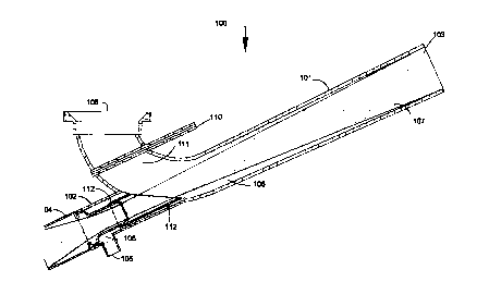
Another preferred embodiment of the present invention is shown in Figure 7. In
this embodiment, the mixing apparatus 100 advantageously includes a diverging
barrel
101. The cross-sectional area of the barrel increases from the proximal end
adjacent to
the nozzle 104 to its distal end 103.
Housing 102 connects to nozzle 104 that provides a high-pressure liquid or
slurry
stream. Water line 105 provides annular water flow 106 around the high-
pressure liquid
or slurry stream emitted from nozzle 104. Preferably, the liquid stream 107
diverges and
expands as it travels from the nozzle 104 along the diverging barrel 101. Most
preferably, the liquid stream 107 diverges and expands into a full cone jet.
Dry cement is
added through input 108 and may be selectively admitted by gate 110 to the
mixing zone
111. The mixing zone 111 is the first contact point for liquid stream coming
from the
nozzle 104 to meet with dry cement. Liquid stream 107 proceeds along the
diverging
9
CA 02305015 2000-04-12
PATENT
ATTORNEY DOCKET NO. 56.0533
INVENTORS: Edward K. Leugemors
William R. McIntire
barrel 101 to distal end 103. Cement slurry that is blown back from the barrel
towards
the nozzle, if at all, may be trapped behind a pipe wall 112 surrounding
nozzle 104.
EXAMPLES
Mixing rates depend on the mixing system which contain, among other elements,
mixer components such as those described in this application. To describe the
improvements over conventional jet mixing systems, we provide comparisons of
field
mix rates and test mix rates with conventional and improved j et mixers. These
tests are
performed with similar conditions regarding the remainder of the mixing
system:
specifically the type of recirculation centrifugal pump and the speed of
operation. The
mix rate is generally limited by the maximum rate at which dry materials can
be ingested
by the mixer.
Example 1
Mixing Bowl Build-up
The current mixer in field application had a build-up of slurry within the
mixer to
the point that the mixing operation was shut down to clean up the interior of
the mixer to
continue mixing. This failure occurred for systems with gypsum as an additive
to any
class cement. Shutdown was required after every 50 to 100 barrels of cement
slurry.
Also, Class A cement occasionally caused the same problem.
Example 2
Enhanced Build-up Test
with Conventional Mixer
10
. . , CA 02305015 2000-04-12
PATENT
ATTORNEY DOCKET NO. 56.0533
INVENTORS: Edward K. Leugemors
William R. McIntire
Three-hundred (300) sacks of Class A neat cement at 15.4 pounds per gallon
density were mixed at 2 barrels per minute ("BPM") for low mixing bowl
pressures. This
rate of mixture enhanced air re-circulation and blowback of slurry. The mixing
bowl
level was controlled by variations in the triplex pump speed. The same
centrifugal pump
that was used to run the re-circulating mixer also supplied the triplex pump.
By varying
the triplex pump rate, the flow rate through the re-circulation nozzle was
varied and the
conditions in the mixer modified. Alternating wet and dry areas were created
in the
mixing bowl. When the triplex pump shifted gears, it momentarily stopped
pumping
which greatly affected the conditions in the mixer and led to undesirable
build-up in the
mixing bowl.
After mixing 300 sacks of cement with the conventional mixer under the
conditions described above, cement build-up filled over one-half of the mixing
bowl
volume and restricted flow of dry cement into the mixing bowl. With restricted
flow, the
maximum mixing rate was only 6 BPM with Class A cement at 15.2 pounds per
gallon
1 S ("PPG"). Before the build-up test, the slurry could be mixed at 6.4 BPM.
Example 3
Enhanced Build-up
Test with Improved Mixer
Following the same procedure as above in Example 2, three hundred (300) sacks
of Class A neat cement were mixed at 15.4 PPG density. Mixing occurs at 2 BPM
for
low bowl pressures. Varying the triplex pump speed controlled the mixing tub
level. In
11
CA 02305015 2000-04-12
PATENT
ATTORNEY DOCKET NO. 56.0533
INVENTORS: Edward K. Leugemors
William R. McIntire
this example, there was no build-up in the mixing bowl, and no reduction in
maximum
cement rates. The improved mixer processed Class A cement at 8 BPM or more.
Example 4
Extreme Case for Build-up Testing:
60% Gypsum and 40% Class H Cement
In field applications, when build-up in the mixer bowl restricts the dry
solids input
rate to provide only 2 BPM as the mixing rate, mixing is stopped to clean the
equipment.
When the cement slurry is comprised of a 60/40 Gypsum-cement blend, the mixing
bowl
build-up restricts the mixing rate to that extent after pumping only 50 to 100
BBL of
slurry.
To test the new mixer design, the Gypsum slurry mixing conditions were made
more difficult than field conditions in three ways. First, the initial mixing
rate was at a
low 2 BPM, creating low mix bowl pressures, which promoted high air re-
circulation
rates back to the mixing bowl. Second, the triplex pump rate was changed by
shifting
pump gears and the change in rate led to varying slurry re-circulation rates
through the
mixer. This tended to wet the ideally dry parts of the mixer bowl. Third, the
gypsum/cement slurry was mixed using only one-third the required amount of
retarder.
The measured setting time for the slurry was only 7 minutes. The low rate
mixing
continued for 30 minutes at 2 BPM. At that time 60 BBL had been pumped under
extreme build-up conditions. Then the mixer rate was increased to determine
the
maximum mixing rate possible. At first the maximum mixing rate at which slurry
12
CA 02305015 2000-04-12
PATENT
ATTORNEY DOCKET NO. 56.0533
INVENTORS: Edward K. Leugemors
William R. Mclntire
density of 15.4 PPG could be achieved was 4 BPM. There was some build-up in
the new
mixer bowl restricting dry materials flow. Then, the dry material eroded the
build-up.
The achievable rate rose to 5 BPM, and then 6 BPM. The test was ended after
reaching 6
BPM. Higher rates were not attempted. If the initial mix rate were 6 BPM,
instead of 2
BPM, there would have been no decrease in rate due to build up with the 60/40
Gypsum-
cement blend.
Example 5
High Mixing Rates Achieved
With the New Mixer Design
Using the conventional mixer, the maximum achievable rate for mixing Class H
neat cement at 16.4 PPG was 6.4 BPM, before any cement build-up occurred,
using a
particular configuration in which the recirculation centrifugal pump also fed
the triplex
pump. The recirculation flow rate decreases when the mix rate (triplex rate)
increases.
All the rate test results given below were achieved with that same system
configuration.
Several tests were run to determine mixing rates for a series of slurnes with
high
solids content including some which are notoriously difficult to mix. These
included:
1. Class H neat cement at 16.4 PPG
2. Class H cement + 35% Silica flour + 0.3% D65 at 17.0 PPG
3. LiteCRETE at 12.4 PPG ("LiteCRETE" is a trademark of Schlumberger
Technology Corporation).
All additive concentrations given are percentages by weight of cement. Below
is
the procedure used for each of the high rate tests:
13
CA 02305015 2000-04-12
PATENT
ATTORNEY DOCKET NO. 56.0533
INVENTORS: Edward K. Leugemors
William R. Mclntire
1 ) Prepared 600 sacks of blended material.
2) Ran mixer under automated density control set for the appropriate slurry
density.
3) Started mixing and pumping cement slurry at 6 BPM.
4) When density was maintained, increased mix/pump rate to 7 and then to 8
BPM.
In the case of each system tested with the improved mixer, the mixer
maintained
slurry rate and density when the mix/pump rate was 8 BPM. This rate was the
limit of
the test equipment. The triplex pump rate was the limiting factor, not the
rate of the
mixer. It is anticipated that with higher achievable triplex pump rates, the
improved
mixer will handle these slurries at mix rates in excess of 8 BPM.
Example 6
Tests of Mixer Capacity for
Educting Cement at High Rates
The effectiveness of a jet mixer system to educt air when run with water as
the
educting liquid is a good indication of the ability of the system to educt
cement-air
mixtures at high rates. Tests were run with different mixer and liquid stream
configurations as described and illustrated in the figures of this
application.
The cement inlet was sealed with a plate having a one-inch hole surrounded by
a
one-inch pipe collar welded to the top side of the plate. Air traveled to the
cement inlet
through a Dwyer brand one-inch rotometer and a one-inch ball valve between the
rotometer and the pipe collar. In addition to measuring the air-flow rates
with the
rotometer, pressure in the mixing bowl also was measured. The water was
recirculated.
A 5 inch x 6 inch centrifugal pumped water from the mix tub to the jet nozzle.
The water
14
CA 02305015 2000-04-12
PATENT
ATTORNEY DOCKET NO. 56.0533
INVENTORS: Edward K. L,eugemors
William R. McIntire
stream flowed through the mixer and back to the mix tub. Air entrained into
the water in
the mixer broke out of the water in the mix tub, so only the water was
recirculated.
The water flow rates were substantially equal in the different tests. Flow
rates
through different nozzles varied slightly, but not enough to affect the
results presented
below. Data on three configurations illustrates the enhancement of eduction
capability
through suppression of air recirculation.
In Case 1, a prior art mixer with a straight liquid stream was tested. The
prior art
system was not as effective in educting air and mixing the slurry. When the
stream was
directed down to contact the bottom of the barrel and adjusted to provide the
maximum
air flow rate and maximum bowl vacuum, the maximum values were about 50 to 55
SCFM and minus 8 inches of Hg vacuum. The air-flow rate was sensitive to the
liquid
stream direction. The liquid stream direction greatly affects the stream
configuration
after contact and interaction with the gun barrel walls.
In Case 2, the mixer in Figure 4 having a diverging fluid stream was tested.
The
educted air flow rate was less sensitive to the direction of the diverging
liquid stream.
The maximum air flow rate and mix bowl vacuum were about 65 SCFM at minus 10
inches of Hg vacuum.
In Case 3, the mixer shown in Figure 6 produced the highest air flow rates and
greatest vacuums in the mixing bowl. These were 72 SCFM and minus 12 inches of
Hg
vacuum.
While the invention has been described with a certain degree of particularity,
it is
manifest that many changes may be made in the details of construction and the
CA 02305015 2000-04-12
PATENT
ATTORNEY DOCKET NO. 56.0533
INVENTORS: Edward K. Leugemors
William R. McIntire
arrangement of the components without departing from the spirit and scope of
this
disclosure. Other embodiments beyond those specific examples cited herein have
been
suggested, and still others may occur to those skilled in the art upon a
reading and
understanding of this specification. All such embodiments shall be included
within the
scope of this invention.
16