Language selection

Search

Patent 2305044 Summary

Third-party information liability

Some of the information on this Web page has been provided by external sources. The Government of Canada is not responsible for the accuracy, reliability or currency of the information supplied by external sources. Users wishing to rely upon this information should consult directly with the source of the information. Content provided by external sources is not subject to official languages, privacy and accessibility requirements.

Claims and Abstract availability

Any discrepancies in the text and image of the Claims and Abstract are due to differing posting times. Text of the Claims and Abstract are posted:

  • At the time the application is open to public inspection;
  • At the time of issue of the patent (grant).
(12) Patent: (11) CA 2305044
(54) English Title: TEMPERATURE LOCK STOP FOR FAUCETS
(54) French Title: BUTEE DE VERROUILLAGE DE TEMPERATURE POUR ROBINETS
Status: Term Expired - Post Grant Beyond Limit
Bibliographic Data
(51) International Patent Classification (IPC):
  • F16K 35/00 (2006.01)
  • F16K 35/02 (2006.01)
(72) Inventors :
  • NELSON, ALFRED C. (United States of America)
(73) Owners :
  • DELTA FAUCET COMPANY
(71) Applicants :
  • DELTA FAUCET COMPANY (United States of America)
(74) Agent: PIASETZKI NENNIGER KVAS LLP
(74) Associate agent:
(45) Issued: 2003-03-18
(22) Filed Date: 2000-04-13
(41) Open to Public Inspection: 2000-12-29
Examination requested: 2000-06-07
Availability of licence: N/A
Dedicated to the Public: N/A
(25) Language of filing: English

Patent Cooperation Treaty (PCT): No

(30) Application Priority Data:
Application No. Country/Territory Date
09/342,806 (United States of America) 1999-06-29

Abstracts

English Abstract

A water mixing valve (10) can selectively adjust temperature by selection mixing of the hot and cold water supplies and be selectively locked in place by a knob (26) fastened via a threaded faster (30). The knob (26) has a spline section (34) seated in a complementary spline section (36) in the valve body (20) to prevent the knob (26) and operating stem (22) from inadvertent rotation.


French Abstract

Une vanne de mélange d'eau (10) peut de manière sélective ajuster la température par mélange sélective des alimentations en eau chaude et en eau froide et peut être verrouillée en position de manière sélective par une poignée (26) fixée via une fixation filetée (30). La poignée (26) présente une section cannelée (34) logée dans une section cannelée complémentaire (36) dans le corps de vanne (20) pour empêcher la poignée (26) et la tige de manuvre (22) d'être manuvrées par inadvertance.

Claims

Note: Claims are shown in the official language in which they were submitted.

-8-
CLAIMS
The embodiments in which an exclusive
property or privilege is claimed are defined as
follows:
1. A rotatable handle assembly for a water
mixing valve characterized by:
a first stem member operably connected to a
mixing valve element and rotatably mounted onto a
mixing valve body and extending therefrom;
a manually operable knob mounted onto said
stem for rotation therewith;
said knob being affixed to said stem by a
fastener in a first lock down position with said knob
having a splined section fitting with a complementary
splined section of said valve body to prevent said stem
from rotation;
said fastener being loosenable to allow said
knob to axially slide on said stem to an adjustable
position which disconnects the splined section of the
knob from the splined section of the valve body to
allow said knob and stem to rotate to a desired mix
position for adjusting temperature of water from said
mixing valve.
2. ~A rotatable handle assembly as defined in
claim 1 further characterized by:
a spring element being interposed between

-9-
said knob and said valve body to bias said knob to said
adjustable position and said fastener when tightened moves
said knob against the bias of said spring to said lock down
position.
3. ~A rotatable handle assembly as defined in claim 2
further characterized by:
said fastener being fastened through a distal
axial end of said knob and a distal axial end of said stem.
4. ~A rotatable handle assembly as defined in claim 3
further characterized by:
said spline section of said valve body being in a
formed female socket section about said stem:
said spline section of said knob being at a
proximate axial end of said knob and surrounding said stem.
5. ~A rotatable handle assembly as defined in claim 3
further characterized by:
said fastener being a threaded fastener with a
head and an allen wrench receptacle, and said head being
recessed mounted in the distal end of said knob.
6. ~A rotatable handle assembly as defined in claim 3
further characterized by:
said knob having external handle ribs for

-10-
facilitating ease of rotation.
7. A rotatable handle assembly as defined in
claim 3 further characterized by:
at least one of said spline sections of said
knob and said valve body being chamfered to provide
automatic meshing of said spline sections as said knob
is moved to the lock down position.

Description

Note: Descriptions are shown in the official language in which they were submitted.


CA 02305044 2000-04-13
TEMPERATURE LOCK STOP FOR FAUCETS
TECHr7ICAL FIELD
The field of this invention relates to a
S temperature mixing valve for mixing hot and cold water
supplies and more particularly to a lock stop for
locking the set mix of water.
BACKGROUND OF THE DISCLOSURE
Many mixing valves have a control stem
mounted to wn operable handle that controls the mix of
hot and cold water to the outlet port in a faucet.
Often the control stem that controls the temperature
mix is separate from the flow rate control portion of
the faucet. As such, the temperature-mixing device can
be located significantly upstream and removed from the
flow rate control valve and the spout or final outlet
port. Remote mixing valves are often used in
conjunction with a bank of electronic faucets which
turn on and off by sensing the presence of a persons
hands or body. The electronic sensing device controls
the on-off position and the flow rate of the valve but
often does not control the mix of the hot and cold
water. The hot and cold water supplies are premixed to
a desired temperature upstream.
As such, the temperature-mixing valve is
often concealed to prevent the casual user or
unauthorized person from tampering with or

CA 02305044 2000-04-13
P3024.1 Masco - 2 -
inadvertently changing the temperature mix. While many
of these mixing valves may be behind closed doors and
remote from the faucet, they still have freely
accessible handles, which may be easily and
inadvertently changed.
What is needed is a temperature-mixing valve
with a knob that can be easily locked in place to
prevent casual tampering or inadvertent adjustment but
can be readily released with a special tool to provide
adjustment to the desired temperature.
SUMMARY OF THE DISChOSURE
In accordance with one aspect of the inven-
tion, a rotatable handle assembly for a mixing valve
includes a first stem member operably connected to a
mixing valve element. The stem member is rotatably
mounted onto a mixing valve body for operating the
mixing valve element to adj ust the mixed hot and cold
water supplies. The stem extends outside of the
valve body. A manually operable knob is mounted onto
the stem and is rotationally affixed with the stem. The
knob is axially movable between a first lock down
position and an operable adjusting position. The knob
has a splined section fitted with a complementary
splined section of the valve body when in the lock down
position to prevent the stem from rotation with respect
to the valve body. A releasable fastener affixed the

CA 02305044 2000-04-13
P3024.1 Masco - 3
knob to the stem in the first lock down position
Preferably, the spline section of the valve
body is a formed female socket section surrounding the
stem and the spline section of the knob is at a
proximate axial end of the knob. At least one of the
spline sections of the knob and valve body are
chamfered to provide automatic meshing of the two
spline sections as the knob is axially moved to the
lock down position.
The fastener can be loosened to allow the
knob to axially slide on the stem to the adjustable
position. When in the adjustable position, the splined
section of the knob is disengaged from the splined
section of the valve body to allow the knob and stem to
rotate to a desired mix position.
A spring element is preferably interposed
between the knob and the valve body to bias the knob to
the adjustable position. The fastener, when tightened,
moves the knob against the bias of the spring to the
lock down position. Preferably the fastener is.fastened
. through a distal axial ends of the knob and the stem.
It is desirable that the fastener is a
threaded fastener with a head having an allen wrench
receptacle and is recess mounted in the distal end of
. 25 the knob. It is also desirable that the knob has a
narrow contour to deter casual or inadvertent
manipulation but has external ribs for promoting manual
grasping of the handle for ease of deliberate rotation.

CA 02305044 2000-04-13
P3024.1 Masco - 4 -
BRIEF DESCRIPTION OF THE DRAWINGS
Reference now is made to the accompanying
5 drawings in which:
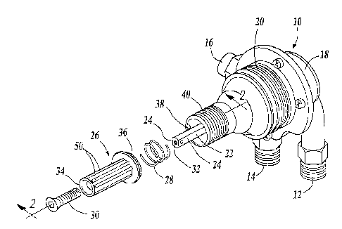
Figure 1 is a perspective and exploded view
of a mixing valve incorporating a lock stop handle
assembly in accordance with one embodiment of the
invention;
10
Figure 2 is cross-sectional fragmentary view
of the handle assembly taken along lines 2-2 shown in
figure 1 with the handle assembly in the lock down
position;
15 Figure 3 is a view similar to figure 2 with
the handle assembly, shown in the adjustable position;
Figure 4 is a cross sectional view taken
along lines 4-4 shown in figure 2;
Figure 5 is a cross-sectional view of the
20 control knob illustrating the knob mounted onto the
stem taken along lines 5-5 shown in figure 3.
DETAILED DESCRIPTION OF THE PREFERRED EMBODIMENT
25 Referring now to figure 1, a commercially
available temperature mixing valve 10 has a cold water
inlet 12, hot water inlet 14, and mixed water outlet 16
in a base fixture 18. A conventional pressure balance

CA 02305044 2000-04-13
P3024.1 Masco - 5 -
proportioning valve and mixing valve element (not
shown) are operably housed within the mixing valve body
20 that is secured to the base fixture 18. The body 20
has a rotatable valve stem 22 extending therefrom. The
5 valve stem 22 is operably connected to the mixing valve
element and is rotatable to adjust the mix of cold and
hot water from the inlets 12 and 14 to outlet 16.
The stem 22 has two flats 24 such that the
stem 22 can be non-rotatably connected to a knob 26
10 through its complementary shaped central aperture 25,
as illustrated in Figure 5. The knob is spring biased
by a spring 28 away from the valve body 20. A threaded
fastener 30 affixes the knob to the stem through the
distal ends 32 and 34 of the respective stem and knob.
15 Referring now to figure 2, when the fastener
30 is fully tightened, the knob 26 is pushed against
the spring bias of spring 28. The knob has its
proximate spline section 36 seated in a spline section
38 of the valve body in socket 40 surrounding the stem
20 22. Both spline sections 36 and 38 are fully circular
and fully surround stem 22. The respective spline
sections 36 and 38 when engaged to each other prevent
the knob 26 and the stem 22 from any rotation, as
illustrated in Figure 4. As such the position of the
25 stem 22 is fixed and not adjustable. As such, this
lock down position of the fastener 30 and knob 25
prevent casual tampering with the stem 22 and
inadvertent adjustment of the mixed water proportions

CA 02305044 2000-04-13
P3024.1 Masco - 6 -
set by the mixing valve 10.
To further deny the casual tampering with the
position of the mixing valve stem, the fastener 30,
when fully tightened, has its head 42 recessed within
5 the distal end 34 of the knob. The head 42 further has
an allen wrench type recess 44 therein. As such, the
fastener is inaccessible to the casual user unless an
allen wrench is used.
However, initial setting and later adjustment
10 of the mixing valve temperature is readily possible.
The threaded fastener can be loosened with the
appropriate allen wrench. As the fastener is loosened,
it moves on its threads and allows the knob 26 to move
to the adjustable position shown in figure 3. In this
15 position, the spline sections 36 and 38 are disengaged
and the knob is free to rotate with the~stem 22 to
adjust the temperature mix of the water.
The knob 26 has a narrow profile about stem
22 to deter casual or in advertent grasping thereof and
20 to give a visual indication that the knob 26 is not the
kind that is freely or commonly adjustable. However,
the knob 26 has handle-facilitating ribs 50 on its
outer side to promote deliberate manual rotation
thereof. The knob 26 if desired can have a textured
25 outer surface or have laterally extending external
levers, or other embossments to further facilitate
manual turning.
When the appropriate setting or adjustment is

CA 02305044 2000-04-13
P3024.1 Masco - 7 -
made, the fastener 30 is re-tightened and the spline
sections 36 and 38 are reseated with each other: Each
spline section has a chamfered or canted end 46 and 48
to provide automatic seating of the two spline sections
5 36 and 38 as the knob 26 is seated into the socket
section 40. The spline 36 and 38 are narrow enough to
provide for seating about multiple positions such as 20
different positions so that the temperature adjustment
increments are relatively small i.e. increments as
10 small as 2° F .
In this fashion, the temperature-mixing valve
allows for adjustment of the water temperature by an
authorized or deliberate action but deters inadvertent
adjustments or casual tampering of the temperature mix.
15 Variations and modifications are possible
without departing from the scope and spirit of the
present invention as defined by the appended claims.

Representative Drawing
A single figure which represents the drawing illustrating the invention.
Administrative Status

2024-08-01:As part of the Next Generation Patents (NGP) transition, the Canadian Patents Database (CPD) now contains a more detailed Event History, which replicates the Event Log of our new back-office solution.

Please note that "Inactive:" events refers to events no longer in use in our new back-office solution.

For a clearer understanding of the status of the application/patent presented on this page, the site Disclaimer , as well as the definitions for Patent , Event History , Maintenance Fee  and Payment History  should be consulted.

Event History

Description Date
Inactive: COVID 19 - Reset Expiry Date of Patent to Original Date 2020-06-16
Inactive: COVID 19 - Deadline extended 2020-06-10
Inactive: COVID 19 - Deadline extended 2020-05-28
Inactive: COVID 19 - Deadline extended 2020-05-14
Inactive: COVID 19 - Deadline extended 2020-04-28
Inactive: Expired (new Act pat) 2020-04-13
Inactive: COVID 19 - Deadline extended 2020-03-29
Common Representative Appointed 2019-10-30
Letter Sent 2015-09-02
Appointment of Agent Requirements Determined Compliant 2014-03-27
Revocation of Agent Requirements Determined Compliant 2014-03-27
Inactive: Office letter 2014-03-26
Inactive: Office letter 2014-03-25
Inactive: IPC from MCD 2006-03-12
Grant by Issuance 2003-03-18
Inactive: Cover page published 2003-03-17
Inactive: Final fee received 2003-01-07
Pre-grant 2003-01-07
Amendment After Allowance Requirements Determined Compliant 2002-12-23
Letter Sent 2002-12-23
Amendment After Allowance (AAA) Received 2002-11-20
Letter Sent 2002-08-07
Notice of Allowance is Issued 2002-08-07
Inactive: Approved for allowance (AFA) 2002-07-23
Application Published (Open to Public Inspection) 2000-12-29
Inactive: Cover page published 2000-12-28
Amendment Received - Voluntary Amendment 2000-07-24
Letter Sent 2000-06-30
All Requirements for Examination Determined Compliant 2000-06-07
Request for Examination Requirements Determined Compliant 2000-06-07
Request for Examination Received 2000-06-07
Inactive: First IPC assigned 2000-06-02
Inactive: IPC assigned 2000-06-01
Filing Requirements Determined Compliant 2000-05-18
Inactive: Filing certificate - No RFE (English) 2000-05-18
Application Received - Regular National 2000-05-17
Letter Sent 2000-05-17

Abandonment History

There is no abandonment history.

Maintenance Fee

The last payment was received on 2002-03-18

Note : If the full payment has not been received on or before the date indicated, a further fee may be required which may be one of the following

  • the reinstatement fee;
  • the late payment fee; or
  • additional fee to reverse deemed expiry.

Patent fees are adjusted on the 1st of January every year. The amounts above are the current amounts if received by December 31 of the current year.
Please refer to the CIPO Patent Fees web page to see all current fee amounts.

Owners on Record

Note: Records showing the ownership history in alphabetical order.

Current Owners on Record
DELTA FAUCET COMPANY
Past Owners on Record
ALFRED C. NELSON
Past Owners that do not appear in the "Owners on Record" listing will appear in other documentation within the application.
Documents

To view selected files, please enter reCAPTCHA code :


To view images, click a link in the Document Description column. To download the documents, select one or more checkboxes in the first column and then click the "Download Selected in PDF format (Zip Archive)" or the "Download Selected as Single PDF" button.

List of published and non-published patent-specific documents on the CPD .

If you have any difficulty accessing content, you can call the Client Service Centre at 1-866-997-1936 or send them an e-mail at CIPO Client Service Centre.


Document
Description 
Date
(yyyy-mm-dd) 
Number of pages   Size of Image (KB) 
Claims 2002-11-19 3 73
Representative drawing 2003-02-12 1 15
Abstract 2000-04-12 1 14
Description 2000-04-12 7 246
Claims 2000-04-12 3 73
Drawings 2000-04-12 2 143
Representative drawing 2000-12-17 1 14
Courtesy - Certificate of registration (related document(s)) 2000-05-16 1 113
Filing Certificate (English) 2000-05-17 1 163
Acknowledgement of Request for Examination 2000-06-29 1 177
Reminder of maintenance fee due 2001-12-16 1 112
Commissioner's Notice - Application Found Allowable 2002-08-06 1 164
Correspondence 2003-01-06 1 35
Correspondence 2014-02-23 8 212
Correspondence 2014-03-17 9 289
Correspondence 2014-03-13 31 986
Correspondence 2014-03-24 1 20
Correspondence 2014-03-25 1 27