Note: Descriptions are shown in the official language in which they were submitted.
CA 02305156 2000-04-04
V~VO 99/1$744 PCT/SE98/01805
-1-
BASE STATION ARCHITECTURE FOR
A MOBILE COMMUNICATIONS SYSTEM
BACKGROUND OF THE INVENTION
Technical ~~jd of the Invention
The present invention relates in general to the mobile communications field
and, in particular, to a base station architecture for a new generation of
mobile
communications systems.
T7 s .rintion of Related Art
The architecture used for any conventional mobile communications base
station (BS) is a channel-based structure. FIGURE 1 is a block diagram of such
a
conventional channel-based mobile communications BS 10. Essentially, as
illustrated
in FIGURE 1, BS 10 allocates one of the fixed channel resources 12a(Ch.l-M1)-
12N(Ch.2-M2) for each call. The baseband section of each channel is used to
handle
all of the possible radio transmission services available for a call, and the
radio
fi-equency (RF) section of each channel includes all of the RF resources
needed for the
call. Each BS sector (1-N) includes the maximum number of channel resources
that
will be needed for that sector over a period of time. Each sector's channel
resources
are combined for transmission and reception via a respective antenna subsystem
( 1-N).
2 0 A significant problem with the conventional channel-based structure
described
above is that it is limited to systems that provide relatively few different
radio
transmission services and the processing requirements for those different
radio
transmission services are virtually the same. However, in the rapidly
expanding
telecommunications field, numerous multimedia communication scenarios are
being
2 5 developed with a large number of different radio transmission services,
with each such
service having substantially different processing requirements. Consequently,
from
a purely statistical standpoint, there is a growing need for communications
network
operators to be able to provide all of the different radio transmission
services for
different users, and the appropriate capacity that will be needed for the
different
3 0 sectors involved.
For a conventional channel-based BS operating in a multimedia scenario with
SUBSTITUTE SHEET (RULE 26)
CA 02305156 2000-04-04
~ WO 99/18744 PCT/SE98/01805
-2-
a fixed amount of resources allocated for each channel and sector, each BS
channel
will have to be equipped with the resources needed for the radio transmission
service
that imposes the highest requirement on that channel's processing capability.
Also,
in a multimedia scenario, each conventional BS sector will have to be equipped
with
the maximum resources that will be needed over time. Consequently, in the
future,
conventional channel-based BS hardware will be unrealistically dimensioned and
thus
provide a maximum processing capability that will far exceed what can be
adequately
supported by any future radio air interface. Therefore, for most of a
conventional BS's
operating time, a large portion of the BS's hardware will be unnecessarily
allocated
but unused. which will significantly and unnecessarily increase the overall
size and
weight of the BS.
The air interface to be used for a so-called "Third Generation" mobile
communications system, such as, for example, a Wideband Code Division Multiple
Access (W-CDMA) system, imposes a whole new set of requirements for a BS
architecture compared to those set forth in previous standards. See, for W-
CDMA, the
"Report on FPLMTS Radio Transmission Technology Special Group (Round 2
Activity Report)," Version E 1.2, January 1997, Association of Radio
Industries and
Businesses CARIB), FPLMTS Study Committee, JAPAN. Essentially, the Base
Transceiver Station (BTS) for a third generation mobile communications system
will
2 0 have to be capable of handling such different end user services as voice,
circuit-
switched data; and packet-switched data. Also, the BTS will have to capable of
supporting a number of different user data rates. For example, a third
generation BTS
will have to support voice signals at an 8 kbps rate, circuit-switched data
from 64 kbps
to 384 kbps, and packet-switched data from approximately 1 kbps to 160 kbps.
2 5 Furthermore, for a third generation BTS, separate protocols (encoding
schemes) will be used to map users to a number of physical channels
characterized by
a symbol rate. An optimized encoding scheme will be used for each of the
channels
for maximum efficiency. A description of these protocols can be found in
avaiiable
documentation for W-CDMA. Thus, in a W-CDMA system, the same BTS should be
3 0 capable of supporting different physical channels with a range of symbol
rates between
16 ksps to 1024 ksps, and also be capable of handling multiple spreading
rates. In
fact, in order for the BTS to be capable of supporting very high user data
rates, it also
SUBSTITUTE SHEET (RULE 26)
CA 02305156 2000-04-04
WO 99/18744 PC'T/SE98/01805
-3-
may have to support a number of chip rates. A third generation BTS will also
have to
be capable of supporting such a network function as "softer" handover (a
handover
where diversity is gained from two or more sectors corresponding to one BTS).
SUMMARY OF THE INVENTION
A BTS structured in accordance with the present invention is divided into a
plurality of functional units which enables the signal processing resources to
be
flexibly allocated and cost-effectively implemented in hardware. Flexible
communications interfaces are created between the BTS units which allows the
signal
processing resources within the units to be used more efficiently.
Essentially, the BTS
l0 hardware is dimensioned to statistically distribute the signal processing
resources
among the different radio transmission services available. Consequently, the
allocated
BTS hardware can be used more efficiently, which minimizes the overall size
and
weight of the base station.
BRIEF DESCRIPTION OF THE DRAWINGS
A more complete understanding of the method and apparatus of the present
invention may be had by reference to the following detailed description when
taken
in conjunction with the accompanying drawings wherein:
FIGURE 1 is a block diagram of a conventional channel-based mobile
communications base transceiver station;
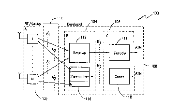
2 0 FIGURE 2 is a simplified schematic block diagram of a base transceiver
station for a mobile communications system, which is structured in accordance
with
a preferred embodiment of the present invention;
FIGURE 3 is a block diagram that illustrates exemplary hardware that can be
used to implement the functions of BTS 100 shown in FIGURE 2;
2 5 FIGUREs 4A and 4B are diagrams that illustrate the flexible allocation of
signal processing resources utilizing the interface A', shown in FIGURE 2, in
accordance with the preferred embodiment of the present invention;
FIGURE S is a detailed block diagram of an RF/sector resource RX sub-unit
shown in FIGURE 3;
3 0 FIGURE 6 is a detailed block diagram of a hardware BBRX sub-unit shown
SUBSTITUTE SHEET (RULE 26)
CA 02305156 2000-04-04
WO 99118744 PCT/SE98/01805
-4-
in FIGURE 3;
FIGUREs 7A and 7B are diagrams that illustrate the flexible allocation of
signal processing resources utilizing the interface B'~ shown in FIGURE 2, in
accordance with the preferred embodiment of the present invention;
FIGURE 8 is a detailed block diagram of a DEC resource shown in FIGURE
3;
FIGUREs 9A and 9B are diagrams that illustrate the flexible allocation of
signal processing resources utilizing the interfaces B'z and A'2 shown in
FIGURE 2,
in accordance with the preferred embodiment of the present invention;
FIGURE 10 is a detailed block diagram of an ENC resource shown in FIGURE
3;
FIGURE 11 is a detailed block diagram of a BBTX resource shown in
FIGURE 3; and
FIGURE 12 is a detailed block diagram of an RF/sector resource TX shown
in FIGURE 3.
DETAILED DESCRIPTION OF THE DRAWINGS
The preferred embodiment of the present invention and its advantages are best
understood by referring to FIGUREs 1-12 of the drawings, like numerals being
used
for like and corresponding parts of the various drawings.
2 0 FIGURE 2 is a simplified schematic block diagram of a BTS for a mobile
communications system, which is structured in accordance with a preferred
embodiment of the present invention. The exemplary BTS shown for the
embodiment
in FIGURE 2 is for a W-CDMA system. However, the present invention is not
intended to be so limited and can be implemented for any type of mobile
2 5 communications system in which functional flexibility in allocating
communications
resources is advantageous. Referring to FIGURE 2, the BTS 100 shown is divided
into three major functional units: RF/sector unit A (102); receiver-
transmitter unit B
( 104); and coder-decoder unit C ( 106). Units B and C are functions included
in the
baseband section 108 of the BTS 100.
3 0 RF/sector functional unit A ( 102) includes all of the resources needed to
convert modulation information from an RF signal to a baseband signal and vice
versa.
SUBSTITUTE SHEET (RULE 26)
CA 02305156 2000-04-04
. VVO 99/1$744 PCT/SE98/01805
-5-
This RF-baseband conversion function of unit A is further divided into
functional sub-
units 1 to N. Each functional sub-unit 1 to N includes the RF-baseband
conversion
resources needed for one associated sector. In contrast with conventional
systems,
these conversion resources allotted for each sector are not associated with
individual
calls. These conversion resources allotted for each sector 1 to N are
preferably
dimensioned in terms of output power, bandwidth, number of diversity antennas,
and
the number of carriers to be conveyed within each sector. For example, from a
functional and associated hardware standpoint, each sector sub-unit 1 to N can
include
a mufti-carrier power amplifier (MCPA). As described in more detail below,
this
1 o novel approach of concentrating the RF conversion resources for BTS I00 in
functional sectors affords substantial savings in BTS hardware size and weight
in
comparison with the conventional base stations that distribute those resources
on each
physical channel.
The functions provided by receiver-transmitter functional unit B (104) and
code-decoder functional unit C ( 106) operate at baseband, and include all of
the
resources needed for individual call setups, wherein each call can impose a
different
demand on the data rate for radio transmission services. As such, all of the
communications resources in functional units B and C can be used for any of
the radio
transmission services provided.
BTS 100 includes a novel connection interface A' (110) between RF/sector
functional unit A ( 102) and receiver-transmitter functional unit B ( 104).
Interface A'
(110) enables any of the communications resources included within functional
units
B (104) and C (106) (e.g., allocated for a specific radio transmission
service) to be
allocated to any of the sectors 1 to N. Consequently, the baseband hardware
2 5 associated with functional units B (104) and C ( 106) can be dimensioned
to handle the
maximum load of the overall BTS, instead of the maximum load of each sector.
In order to enhance the flexible allocation of resources and thereby
significantly reduce the size of the hardware in BTS 100, the baseband
section's (108)
functional units B (104) and C (106) include the capability to freely allocate
the ,
3 o baseband resources in accordance with the needs of the radio transmission
service
capabilities required for a specific call. The baseband section's (108)
functional units
also include the capability of freely allocating the baseband resources for
uplink and
SUBST11TUTE SHEET (RULE 26)
CA 02305156 2000-04-04
j WO 9918744 PCT/SE98/01805
-6-
downlink processing of asymmetrical radio transmission services.
As shown in FIGURE 2, the baseband section (108) includes four functional
units: a receiver unit 112 and decoder unit 114 for uplink traffic; and a
transmitter unit
116 and coder unit 118 for downlink traffic. Preferably, the hardware
associated with
the baseband section 108 can be allocated between those four functions on a
call by
call basis. Alternatively, this hardware can be reallocated on a recurring
basis (e.g.,
once every 24 hours) in order to better follow the fluctuations of the service
mix.
Specifically, for the uplink signals, the receiver unit 112 functions to
separate
the modulation information from the RF/sector unit 102 into user specific
channels,
by multiplying the input signal from RF/sector unit 102 by user specific short
and long
codes. At the same time, the receiver unit 112 functions to demodulate the
input
signal and detects the data from the resulting signal. The decoder unit 114
deinterleaves the input data and performs channel decoding. Using an
Asynchronous
Transfer Mode (ATM) protocol, the output signal from decoder unit 114 is
coupled
via a transmission line interface to an output for further processing and/or
display.
For the downlink signals, using an ATM protocol, input data is coupled via a
transmission line interface from an input to the coder unit 118, whore the
data is
channel coded and interleaved. The coded data is coupled to the transmitter
unit 116
and multiplied with a user-specific short code, which can be different for
each
2 0 sector/frequency. At the same time, the transmitter unit defines the
modulation to be
used. Also, as described below, the user-specific spreaded data from different
users
are added sectorwise, and thereafter multiplied with a sector/frequency-
specific long
code.
As described earlier, the baseband section 108 is divided into two functional
2 5 units B (104) and C (106), which eases the implementation of more flexible
resource
allocation hardware. One important reason for dividing the baseband section i
08 as
shown in FIGURE 2 is that the two fimctional units B and C have quite
different
fimctional structures and implementation technologies. For example, the
transmitter
unit 116 and receiver unit 112 operate with chip rates in the range of the RF
bandwidth
3 0 for the BTS. The processing hardware to implement such functional
capabilities is
preferably field-programmable gate arrays (FPGAs) or Application Specific
Integrated
Circuits (ASICs), rather than digital signal processors (DSPs). On the other
hand, the
SUBSTITUTE SHEET (RULE 26)
CA 02305156 2000-04-04
WO 99/18744 PCT/SE98/01805
_'7_
processing in the coder unit 118 and decoder unit 114 is accomplished at a
symbol
rate, or at about a 10-100 times lower rate than the transmitter/receiver
units. This
lower rate processing in the coder/decoder allows a designer to more freely
choose an
implementation technology. Notably, considering the opportunity to integrate
the
associated hardware on a step-wise basis, it is advantageous to separate the
functional
units in block B (104) from those in block C (106).
Another important reason for dividing the baseband section 108 as shown is
that the functional units in blocks B (104) and C (106) have different pooling
potentials. For example, the transmitter unit 116 in block B includes channel
1 o resources whose processing requirements are independent of the data rate
of the radio
transmission services being processed. The processing requirements of the
receiver
unit 112 in block B are also independent of the radio transmission services'
data rates,
but in this case, at higher data rates, the processing requirements of the
receiver unit
112 can be scalable to the data rate of a particular radio transmission
service involved.
On the other hand, the coder unit 118 and decoder unit 114 in block C includes
channel resources whose processing requirements are fully scalable to the data
rate of
the radio transmission service involved. Thcrefore, in this case, the
scalability of the
functional units in block C ( 106) is facilitated by separating the functions
of block C
from those in block B (104).
2 0 Additionally, many of the multimedia radio transmission services being
provided have asymmetrical characteristics with respect to the others, and
these
different characteristics can vary over time. In such an environment, the
transmitter
and receiver resources in functional block B (104) and the coder and decoder
resources
in functional block C (106) can be more flexibly and efficiently utilized in
processing
2 5 these asymmetrical services, because these resources can be freely
allocated for uplink
or downlink processing, either on a per call or recurring (e.g., 24 hour)
basis.
However, as illustrated by the exemplary embodiment shown in FIGURE 2,
the resources utilized for upiink and downlink signal processing are allocated
to
different physical (hardware) units in blocks B (104) and C (106). Since the
3 o exemplary BTS shown in FIGURE 2 is for a W-CDMA system, the resources
needed
for downlink signal processing can be 5-10 times smaller and less complex than
the
resources needed for uplink signal processing. Consequently, separating the
uplink
SUBSTITUTE SHEET (RULE 26)
CA 02305156 2000-04-04
WO 99/18744 PCT/SE98/01805
_g_
and downlink signal processing functions in the BTS 100 shown in FIGURE 2 does
not affect to a significant degree its uplink and downlink resource allocation
flexibility, but instead advantageously facilitates the step-wise hardware
integration
of each functional unit shown.
Notably, a novel aspect of the BTS 100 shown in FIGURE 2, which is a BTS
architecture that can be implemented for a W-CDMA system (but can also be
applied
to a BTS for a CDMA system), because of the transmitter unit's (116)
relatively low
complexity, the transmitter hardware that can be utilized has a small impact
on the
overall size of the BTS. Consequently, the transmitter unit's (I16) individual
1 o hardware resources can be allocated for each sector/frequency, up to the
maximum
capacity that can be handled in accordance with the W-CDMA air interface
specification.
For "softer" handovers, the same data can be transmitted in a plurality of the
N possible sectors. This data in different sectors can be spread by different
short codes
(and a sector-specific long code), which advantageously allows pooling of the
spreading hardware resources by sectors in BTS 100. Consequently, by being
able to
sector pool the transmitter's ( 116) hardware resources, the data rate of the
interface A'z
(described in detail below) can be significantly reduced in comparison with
conventional approaches that utilize a pool of spreaders for the whole BTS.
2 o In accordance with the preferred embodiment of the present invention, the
capability of flexibly allocating processing resources in BTS 100 can be
provided as
follows. Each channel resource allocated for uplink signal processing in the
receiver
unit 112 can simultaneously receive signals from different sectors (1 to N) of
the
RF/sector unit 102. Consequently, the receiver unit 112 can dynamically select
which
2 5 input signals to process at any one point in time. This capability allows
flexible
capacity for each sector at call setup. For "softer" handovers during a call,
this
capability gives significant savings in hardware volume. In other words, the
same
receiver resources can be used during the whole "softer" handover operation.
As such,
during "softer" handovers or similar operations, the BTS 100 is not required
to
3 0 reallocate or double allocate the receiver's signal processing resources.
Specifically, the communications interface A', between the RF/sector section
102 and the receiver unit 112 provides a significant portion of the resource
allocation
SU6STfTUTE SHEET (RULE 26)
CA 02305156 2000-04-04
WO 99/18744 PCT/SE98/01805
-9-
flexibility for BTS 100. The interface A', comprises a separate high speed
serial
connection from each RF/sector resource in section 102 to the common receiver
unit
112. The serial connections are made through interfaces transferred to a high
speed
parallel bus, which carries all of the incoming sector information to the
receiver unit
112.
The signal processing resources in the decoder unit 114 can be freely
allocated
to any resource in the receiver unit 112. This resource allocation flexibility
for the
decoder is accomplished through the communications interface B',, which
comprises
a number of moderately-high speed time-slotted serial buses connected between
the
receiver unit 112 and the decoder unit 114. Each signal processing resource in
the
receiver unit 112 can place data on a specific time-slot on one of the buses,
and the BS
manager (e.g., an operating system not explicitly shown) directs a signal
processing
resource in the decoder unit just where to fetch the data from that slot on
the bus.
The decoder unit 114 provides flexible allocation of hardware resources to
different radio transmission services for different calls. In other words, a
high speed
data rate service can utilize the same decoder unit (114) resources that had
been
previously utilized for speech calls. For example, the same decoder unit (114)
hardware can process 100 calls at 8 kbps (data rate) each, as 8 calls at 100
kbps each.
This capability of pooling the decoder resources in BTS 100 significantly
reduces the
2 o size of the decoder hardware that can be used.
For downlink signal processing, the signal processing resources in the coder
unit 118 can be flexibly allocated to handle different radio transmission
services in
essentially the same way as they are handled in the decoder unit 114.
Consequently,
this capability of pooling the signal processing resources in the coder unit
118
significantly reduces the size of the coder hardware that can be used.
Specifically, by using the interface B'2, a user-specific signal processing
resource in the coder unit 118 can be allocated to any sector in the
transmitter unit 116,
since the transmitter unit's resources are sector/frequency allocated. The
communications interface B'~ between the coder unit 118 and transmitter unit
116 is
3 0 a moderately-high speed time-slotted serial/parallel bus. Consequently,
each signal
processing resource in the coder unit 118 can place data on a specific time-
slot on the
bus, and the BS manager can direct a signal processing resource in the
transmitter unit
SUBSTITUTE SHEET (RULE 26)
CA 02305156 2000-04-04
WO 99%18744 PCT/SE98/01805
-10-
116 just where to fetch the data from that slot on the bus.
In general, this downlink functional capability in the baseband section 108 of
BTS 100 provides a significant amount of flexible capacity per sector. For
"softer"
handover functionality on the downlink, this capability facilitates the
"softer"
handover operation and saves substantial baseband hardware resources. The same
coder unit signal processing resources can be mapped to the transmitter unit's
resources simultaneously for an unlimited number of sectors ( 1 to N).
Consequently,
the BTS 100 shown in FIGURE 2 is not required to reallocate or double
allocate~the
signal processing resources of the coder unit 118 during the complete "softer"
handover (or other similar) operations. - .
The output of each sector-allocated signal processing resource in transmitter
unit 116 is coupled via communications interface A'Z to a corresponding signal
processing resource in the RF/sector section 102. The communications interface
A'2
is preferably implemented by N point-to-point high speed serial interface
connections.
In general, with the BTS 100 shown in FIGURE 2, in order to appropriately
handle the processing of asymmetric radio transmission services, the uplink
and
downlink signal processing resources in BTS 100 can be allocated independently
at
call set up or during a call. In other words, the BTS 100 can flexibly
increase or
decrease the uplink and downlink signal processing resources being used during
a call.
2 0 For example, for processing high data rate radio transmission services,
the BS manager
can have BTS 100 allocate several parallel channel resources for the uplink
and/or
downlink to a call. For the downlink allocation, incoming user data to the
coder unit
118 can be mapped to several of the coder unit's signal processing resources,
and the
output of each such resource can be mapped to a specific short code per
2 5 sector/frequency in the transmitter unit 116.
A significant advantage of the BTS 100 shown in FIGURE 2 and described
above in accordance with the present invention is that the architecture makes
it
possible to minimize the hardware size for a given radio transmission service
mix. For ,
example, if the dominant calls being processed are speech calls with low data
rates,
3 0 many receiver resources will be needed, but less decoding and coding
resources will
be needed. On the other hand, the opposite is true if the dominant calls being
processed are data calls with high data rates, because many coding and
decoding
SUBSTITUTE SHEET (RULE 26)
CA 02305156 2000-04-04
WO 99/18'44 PCT/SE98/01805
-I1-
resources will be needed, but less receiver resources will be needed.
Consequently,
the present invention makes it possible for an operator to optimally and cost-
effectively outfit the BTS with the appropriate hardware resources, in
accordance with
a predicted radio transmission service mix.
The hardware size of the BTS 100 can also be optimized to process asymmetric
traffic on the uplink and downlink. For example, if more downlink than uplink
traffic
is being processed by the BTS, then more signal processing resources in the
coder unit
118 are needed, and less resources in the receiver unit 112 and decoder unit
114 are
needed. Consequently, an operator can equip the BTS (100) with uplink and
downlink
signal processing resources based on a predicted future need.
For the baseband section 108 of the BTS, a number of different factors can
come into play when determining the maximum amount of signal processing
resources
that can be allocated to a specific function. For example, the number of
channel
resources in the receiver unit 112 is limited to N (number of sectors) times
the number
of speech channels per sector that can be supported by the air interface. The
number
of resources per sector in the transmitter unit 116 is limited by the number
of
orthogonal spreading codes used. The maximum number of resources in the
decoder
unit 114 is limited to N {number of sectors) times the number of resources
needed
within a sector for the maximum total data rate within a sector; scalable
between the
2 o radio transmission services.
The number of resources in the coder unit 118 is limited similar to the
limitations for the decoder unit 114 described above. However, the potential
maximum data rate for the coder unit 118 is higher than that for the decoder
unit,
because of the orthogonality of the downlink signals.
2 5 FIGURE 3 is a block diagram that illustrates exemplary hardware that can
be
used to implement the functions of BTS 100 shown in FIGURE 2. A BTS 200
includes RF/sector unit 202 and baseband section 208. For this embodiment,
RF/sector unit 202 shown in FIGURE 3 is one sub-unit out of a possible N sub-
units
within RF/sector functional unit A ( 102) shown in FIGURE 2. In other words,
the
3 0 signal processing resources in RF/sector unit 202 are the hardware
resources for one
sector. For the exemplary embodiment shown in FIGURE 3, these sector hardware
resources include a transmitter MCPA 220, a receiver low noise amplifier (LNA)
222,
SUBSTITUTE SHEET (RULE 26)
CA 02305156 2000-04-04
'WO 99/18744 PCT1SE98/01805
-12-
a transceiver RF part 224, and a transceiver digital part 226.
The hardware resources for the baseband unit 208 include one of the plurality
of baseband transmitter sub-units BBTX in the transmitter unit 216, and one of
the
plurality of baseband receiver sub-units BBRX in the receiver unit 212. The
sub-unit
BBTX includes all of the transmitter resources for a sector ( 1 to N) for all
carrier
frequencies within that sector. The receiver unit 212 also includes one of the
plurality
of baseband random access sub-units BBRA, and one of the plurality of baseband
interface sub-units BBIF. The BBRA sub-unit controls the upiink accesses for
the
BTS's control channel. The BBIF sub-unit forms part of interface A',. These
baseband receiver and transmitter sub-units in hardware unit 204 correspond to
the
functional receiver and transmitter units of unit 104 in FIGURE 2.
The baseband hardware unit 208 also includes one of a plurality of decoder
sub-units DEC (214) and encoder sub-units ENC (218). These DEC and ENC sub-
units perform the respective decoder and encoder functions of the sub-units
114 and
118 shown in FIGURE 2.
A timing unit (TU) supplies synchronization and timing signals for all of the
hardware units in BTS 200. A main processor (MP) manages the resource
allocation
for all of the hardware units in the BTS.
For downlink data flow through BTS 200, user data is input from the
2 0 transmission line interface towards the Radio Network Controller (RNC) and
coupled
thmugh the exchange terminal (ET) ATM to an AAL2 link termination (ALT) and on
to a service multiplexer (SMX). The data is then passed by the SMX to an ATM
interface host (ATM-IFH) sub-unit 228 and on to an ATM interface client (ATM-
IFC)
sub-unit 230. The data is then coupled to the ENC sub-unit 218, where the data
is
2 5 channel coded and interleaved. The channel coded data is then coupled to
the BBTX
sub-unit, where the data is multiplied with a user-specific short code. The
user-
specific (spread) data are added sector-wise and multiplied with a
sector/frequency-
specific long code. The encoded signal is then coupled through the transceiver
digital
part 226, the transceiver RF part 224, and the MCPA to the transmit antenna.
3 0 For uplink data flow through BTS 200, the incoming signal from the receive
antenna is coupled through the low noise amplifier 222, the transceiver RF
part 224,
and the transceiver digital part 226 to the BBIF sub-unit. The BBIF forms a
part of
SUBSTITUTE SHEET (RULE 26)
CA 02305156 2000-04-04
WO 99/18744 PCT/SE98/01805
-13-
interface A', in FIGURE 2. The incoming signal is coupled to the BBRX sub-
unit,
which separates the modulation information in the incoming signal into user-
specific
channels by multiplying the incoming signal by user-specific short and long
codes.
The BBRX sub-unit also demodulates the incoming signal and detects the data
from
the resulting demodulated signal. The data is then coupled to the DEC sub-unit
214,
which deinterleaves the incoming data and performs channel coding. The decoded
data are then coupled by the ATM-IFC 234 to the ATM-IFH 232. The data are then
coupled to the ALT, where the SMX couples the data to the ET and out over the
transmission line interface towards the RNC for display.
FIGURBs 4A and 4B are diagrams that illustrate the flexible allocation of
signal processing resources utilizing the interface A', shown in FIGURE 2, in
accordance with the preferred embodiment of the present invention. As shown in
the
detailed block diagram of an RF/sector resource sub-unit 202 in FIGURE S, from
each
RF/sector resource TRX-DIG 226 (1-N) in FIGURE 4A, there is a high speed
serial
connection 227 (1-N) to a baseband interface sub-unit BBIF. The high speed
connection 227 and BBIF are both parts of the interface A',. This BBIF
transfers the
serial connections into one high speed parallel bus 229 that carries
information from
all sectors (1-N).
Within the baseband receiver unit 212, there is a plurality of hardware BBRX
2 o sub-units, as shown by the detailed block diagram of FIGURE 6. Each such
BBRX
sub-unit includes a plurality of BBRX signal processing resources. By a
plurality of
selectors on the input of each BBRX resource, one of these plurality of
resources can
access I and Q information from any combination of the carrier, sector, and
diversity
antenna signals. During a "softer" handover operation, one BBRX resource
processes
2 5 information firm one carrier signal, but from different sectors or
antennas. The I and
Q information contains modulation information from many radio paths, with
different
multipath delays, entering a sector/antenna. The BBRX signal processing
resource can
dynamically choose any of the paths from any sector, and simultaneously
process
these paths. FIGURE 4B illustrates how the I and Q information from different
3 0 sectors, carriers and antennas are mapped onto the parallel bus 229 by the
BBIF sub-
unit.
FIGUREs 7A and 7B are diagrams that illustrate the flexible allocation of
SUBSTtME SHEET (RULE 26)
CA 02305156 2000-04-04
~WO 99/18744 PCT/SE98/O1805
-14-
signal processing resources utilizing the interface B', shown in FIGURE 2, in
accordance with the preferred embodiment of the present invention. As shown in
FIGURE 7A, from each BBRX sub-unit in receiver unit 212, there is a serial bus
connection 231 (1-M3) to each DEC hardware sub-unit 214 that carries I and Q
soft
information data from all physical channeUBBRX resowces within a BBRX hardware
sub-unit. Each BBRX resource occupies one physical channel-slot on the bus
231.
This time-slot can carry three different symbol rates (e.g., 32, 64 and 128
ksps). For
symbol rates of 256, 512 or 1024 ksps, two, four or eight consecutive time-
slots are
used. As shown by FIGURE 7B, this bus structwe facilitates the extraction of
data by
a physical channel selector in the DEC resource shown in the detailed block
diagram
of FIGURE 8. Each DEC resource within the DEC hardware sub-unit 214 can access
all of the physical channel slots on all of the serial buses 231 (1-M3) shown
in
FIGURE 7A.
FIGURES 9A and 9B are diagrams that illustrate the flexible allocation of
signal processing resources utilizing the interfaces B'2 and A'Z shown in
FIGURE 2,
in accordance with the preferred embodiment of the present invention. FIGURE
9A
shows that each ENC resource (as shown in the detailed block diagram of FIGURE
10) in the ENC hardware sub-unit 218 can map its information on a time-slotted
serial
bus (B'Z). For this embodiment, there are two parallel buses for I and Q
information,
2 o respectively. During time T (FIGURE 9B), each ENC resource can map a
plurality __
of consecutive symbols onto the bus B'Z. For the example shown in FIGURE 9B,
the
number of consecutive symbols is 1, 2, 4 and 8 for symbol rates of 32, 64, 128
and 256
ksps, for different ENC resources (such as the one in the detailed block
diagram in
FIGURE 10). The order in which the different symbol rates are allocated is
2 5 determined by the resowce allocations from the main processor shown in
FIGURE 3.
Each BBTX sub-unit (216) hardware resource, as shown in FIGURE 1 I, can
access any ENC resource (FIGURE 10) mapped onto the bus B'2. During a "softer"
handover operation, information from one ENC resowce (FIGURE 10) can be mapped
to BBTX resowces on different BBTX hardware sub-units, thus resources can be
3 o utilized on different sectors but for the same carrier.
In FIGURE 9A, the BBTX hardware sub-unit (216) has a separate pool of
BBTX resources for each carrier. For this embodiment, these resowces are
combined
SUBSTITUTE SHEET (RULE 26)
CA 02305156 2000-04-04
WO 99/18744 PCT/SE98/01805
-1$-
into an I and Q information/carrier. Within the BBTX sub-unit (216), the
information
from different carriers are then multiplexed (MUX) into the data bus A'~ that
can
provide point-to-point connection with corresponding RFlsector resources, such
as the
RF/sector resource (TX) shown in the detailed block diagram of FIGURE 12. For
this
embodiment, there are N such connections.
Although a preferred embodiment of the method and apparatus of the present
invention has been illustrated in the accompanying Drawings and described in
the
foregoing Detailed Description, it will be understood that the invention is
not limited
to the embodiment disclosed, but is capable of numerous rearrangements,
1 o modifications and substitutions without departing from the spirit of the
invention as
set forth and defined by the following claims.
SUBSTITUTE SHEET (RULE 26)