Language selection

Search

Patent 2305205 Summary

Third-party information liability

Some of the information on this Web page has been provided by external sources. The Government of Canada is not responsible for the accuracy, reliability or currency of the information supplied by external sources. Users wishing to rely upon this information should consult directly with the source of the information. Content provided by external sources is not subject to official languages, privacy and accessibility requirements.

Claims and Abstract availability

Any discrepancies in the text and image of the Claims and Abstract are due to differing posting times. Text of the Claims and Abstract are posted:

  • At the time the application is open to public inspection;
  • At the time of issue of the patent (grant).
(12) Patent: (11) CA 2305205
(54) English Title: APPARATUS FOR STACKING SHEETS
(54) French Title: APPAREIL D'EMPILAGE DE FEUILLES
Status: Expired and beyond the Period of Reversal
Bibliographic Data
(51) International Patent Classification (IPC):
  • B65H 29/00 (2006.01)
  • B65G 57/10 (2006.01)
  • B65H 29/34 (2006.01)
  • B65H 29/36 (2006.01)
  • B65H 31/34 (2006.01)
(72) Inventors :
  • LEHTIMAKI, TEUVO (Finland)
(73) Owners :
  • SUNDS DEFIBRATOR PANELHANDLING OY
  • VALMET PANELHANDLING OY
(71) Applicants :
  • SUNDS DEFIBRATOR PANELHANDLING OY (Finland)
  • VALMET PANELHANDLING OY (Finland)
(74) Agent: MARKS & CLERK
(74) Associate agent:
(45) Issued: 2006-12-12
(86) PCT Filing Date: 1998-10-06
(87) Open to Public Inspection: 1999-04-15
Examination requested: 2003-06-03
Availability of licence: N/A
Dedicated to the Public: N/A
(25) Language of filing: English

Patent Cooperation Treaty (PCT): Yes
(86) PCT Filing Number: PCT/FI1998/000780
(87) International Publication Number: FI1998000780
(85) National Entry: 2000-04-04

(30) Application Priority Data:
Application No. Country/Territory Date
973906 (Finland) 1997-10-08

Abstracts

English Abstract


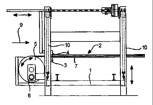
The invention relates to an apparatus for stacking at
least two sheets, said apparatus comprising a vertically
movable stacking platform and an intermediate support
member with a width advantageously substantially equal to
that of said stacking platform, which intermediate support
member is adapted movable into a position above the
stacking platform or above a stack of at least one sheet
placed on said platform and over which intermediate support
member the next sheet or sheet substack is brought and
which intermediate support member is then retracted from
between the overlying sheets, whereby the sheets are
simultaneously aligned against a back gage. The
intermediate support member is made from a multilayer
material having at least one layer made from a material
having a substantially high tear resistance.


French Abstract

Cette invention concerne un appareil permettant d'empiler au moins deux feuilles, lequel appareil comprend une plate-forme d'empilage (1) pouvant se déplacer verticalement, ainsi qu'un élément de support intermédiaire (2) qui possède de préférence une largeur égale à celle de la plate-forme d'empilage. Cet élément de support intermédiaire peut se déplacer en une position située au dessus de la plate-forme d'empilage ou au dessus d'une pile d'une ou de plusieurs feuilles placées sur ladite plate-forme. La feuille suivante ou la sous-pile de feuilles suivantes sont placées au dessus de l'élément de support intermédiaire qui est ensuite rétracté d'entre les feuilles se trouvant au dessus de lui. Les feuilles sont alignées simultanément contre un repère arrière (3, 4). L'élément de support intermédiaire (2) est fait d'un matériau multicouches dont une couche (2m) au moins est faite d'un matériau possédant une résistance au déchirement relativement élevée.

Claims

Note: Claims are shown in the official language in which they were submitted.


6
The embodiments of the present invention in which an
exclusive property or privilege is claimed are defined as
follows:
1. An apparatus for stacking at least two sheets, said
apparatus comprising a vertically movable stacking platform
and an intermediate support member with a width
advantageously substantially equal to that of said stacking
platform, which intermediate support member is adapted
movable into a position above the stacking platform or
above a stack of at least one sheet placed on said platform
and over which intermediate support member the next sheet
or sheet substack is brought and which intermediate support
member is then retracted from between the overlying sheets,
whereby the sheets are simultaneously aligned against a
back gage, wherein:
said intermediate support member is made from a flexible
multilayer material having at least one layer made from a
material having a substantially high tear resistance; and
said intermediate support member is rolled about a
support roller element when it is retracted.
2. The apparatus as defined in claim 1, wherein at least
one surface layer is made from a soft material for

7
protecting the sheets from marring each other during
stacking.
3. The apparatus as defined in claim 1 or 2, wherein a
surface layer of said intermediate support member is made
from a felt-like material for protecting the sheets from
marring each other during stacking.
4. The apparatus as defined in any one of claims 1 to 3,
wherein at least one inner layer of said intermediate
support member is made from a fabric of substantially high
tear resistance such as a metallic fabric.
5. The apparatus as defined in any one of claims 1 to 4,
wherein said intermediate support member comprises two
surface layers and one middle layer.
6. The apparatus as defined in any one of claims 1 to 5,
wherein a surface layer is made from a felted-surface
polymer fabric for protecting the sheets from marring each
other during stacking.
7. The apparatus as defined in any one of claims 1 to 6,
wherein said layers are bonded to each other by glueing.

8
8. An intermediate support member for use in an apparatus
defined in any one of claims 1 to 7, wherein said
intermediate support member is made from a multilayer
material having at least one layer of a material having a
substantially high tear resistance.
9. The intermediate support member as defined in claim 8,
wherein at least one surface layer is made from a soft
material for protecting the sheets from marring each other
during stacking.

Description

Note: Descriptions are shown in the official language in which they were submitted.


CA 02305205 2005-02-02
1
~PPAR~TLS FOR STACKING SHEETS
The present invention relates to an apparatus for stacking
at least two sheets.
Apparatuses of the type concerned in the invention are
used for stacking sheet substacks at least one sheet
thick into higher stacks. From the prior art are known
embodiments utilising a carrier means similar to a con-
veyor band as an intermediate support member at a
stacking station. These conventional arrangements are
hampered by a number of drawbacks including, among
others, an inferior resistance of the material used in
their intermediate support member to pointed/edged
mechanical stress, which tends to cause tearing and
cutting of the support means surface. Moreover, the
conveyor material has in certain situation been able to
mar the sheet material being stacked.
If is an object of the present invention to provide an
apparatus capable of overcoming the disadvantages of the
above-described prior=art embodiments.
In one aspect, the invention provides an apparatus for
stacking at least two sheets, said apparatus comprising a
vertically movable stacking platform and an intermediate
support member with a width advantageously substantially
equal to that of said stacking platform, which intermediate
support member is adapted movable into a position above the
stacking platform or above a stack of at least one sheet
placed on said platform and over which intermediate support
member the next sheet or sheet substack is brought and
which intermediate support member is then retracted from

CA 02305205 2005-02-02
la
between the overlying sheets, whereby the sheets are
simultaneously aligned against a back gage, wherein:
said intermediate support member is made from a flexible
multilayer material having at least one layer made from a
material having a substantially high tear resistance; and
said intermediate support member is rolled about a
support roller element when it is retracted.
In one embodiment, at least one surface layer is made from
a soft material for protecting the sheets from marring each
other during stacking.
In one embodiment a surface layer of said intermediate
support member is made from a felt-like material for
protecting the sheets from marring each other during
stacking. At least one inner layer of said intermediate
support member may be made from a fabric of substantially
high tear resistance such as a metallic fabric. The
intermediate support member may comprise two surface layers
and one middle layer. In another embodiment, a surface
layer may be made from a felted-surface polymer fabric for
protecting the sheets from marring each other during
stacking. The layers may be bonded to each other by
glueing.

CA 02305205 2005-02-02
lb
In another aspect, the invention provides an intermediate
support member for use in an apparatus as described herein,
wherein said intermediate support member,is made from a
multilayer material having at least one layer of a material
having a substantially high tear resistance. In one
embodiment, at least one surface layer may be made from a
soft material for protecting the sheets from marring each
other during stacking.
An apparatus according to the invention offers a number
of significant benefits. The structure of the inter-
mediate support member used in the apparatus provides an
extremely durable construction. The multilayer structure
of the intermediate support member has a very good wear
resistance: It is also resistant against cutting. Its
soft outer layers are incapable of marring the sheets
being stacked. Furthermore, its the felt-like surface
texture complies to the small surface irregularities of
the stacked sheets. Moreover, the apparatus is capable of'
making extremely neat stacks. The stack edges become
straight as the intermediate support member can push the

CA 02305205 2000-04-04
WO 99/18023 PCT/FI98/00780
2
transferred stacks of sheets very reliably against a back
gage.
In the following the invention will be examined in
greater detail with reference to the appended drawings,
in which
Figure 1 shows an apparatus according to the invention in
a side view;
Figure 2 shows an apparatus according to the invention in
an end view;
Figure 3 shows an apparatus according to the invention in
~5 a top view; and
Figure 4 shows the structure of the intermediate support
member used in the apparatus according to the invention
schematically in sectional view.
Referring to the diagrams, the apparatus according to the
invention shown therein comprises a framework 10 having a
vertically movable platform 1 adapted thereto. The appa-
ratus includes an intermediate support member 2 adapted
to be movable into a position above the stacking platform
1 or above a stack of at least one sheet placed on said
platform. The width of the intermediate support member 2
is advantageously made essentially equal to the width of
the stacking platform 1. The next sheet or substack of
3o sheets is brought on the intermediate support member 2 by
means of, e.g., a pusher 4. The function of the inter-
mediate support member is to make the transfer of sheets
onto the underlying stack of sheets easier and to protect
the substacks of sheets from marring each other. When the
intermediate support member 2 is removed from between the
stacked sheets, the sheets are allowed to rest on each
other simultaneously as they are pushed at least by their

CA 02305205 2000-04-04
WO 99/18023 PCT/FI98/00780
3
one edges against a back gage 3, 4. The pusher 4 can act
as a back gage during the retraction of the intermediate
support member. The apparatus also includes means 5, 6,
7, 8 for moving the intermediate support member to above
the stacking platform 2 and retracting the same from
between the sheets. The intermediate support member 2 is
connected by its one end to a support roller element 5,
whose driven rotation by a drive means 6 forces the
intermediate support member 2 to retract in a winding
manner from the stacking area of the sheets. The appara-
tus further includes guides 7 along which the movable
intermediate support member is adapted to run. The guides
serve to support carriages 8 to which the intermediate
support member 2 is connected, e.g., by its edges.
The sheets or sheet substacks to be stacked are fed from
the direction of arrow 9 marked in Fig. 2 by means of the
pusher 4 onto the stacking platform 1 or an intermediate
support member 2 driven over the stack of sheets already
zo stacked on the platform. When the new substack of sheets
is fully pushed home in the stacking station, the inter-
mediate support member 2 is removed from the gap remain-
ing between the stacked sheets by actuating the roller
element 5 to wind the intermediate support member away
via the slot between the pusher 4 and the back gage 3.
Then, the upper part of the lower substack is supported
by the back gage 3, while at least the lower part of the
upper substack is supported by the pusher 4 which is
located in essentially the same plane with the back gage.
3o Next, the platform 1 is lowered and the intermediate
support member 2 is driven above the sheet stack resting
in the stacking area, whereby a new sheet substack can be
transferred onto the intermediate support member.
The intermediate support member 2 is made from a multi-
layer material having at least one layer 2m of a material
having a substantially high tear resistance. Furthermore,

CA 02305205 2000-04-04
WO 99/18023 PCT/FI98/00780
4
at least one surface layer 2s of the member is made from
a soft material.
The surface layer 2s of the intermediate support member 2
may be made from, e.g., a felt-like material. At least
one inner layer 2m of the intermediate support member 2
is made from a fabric of substantially high tear resis-
tance such as a metallic fabric. One advantageous choice
for the middle layer is a metal wire fabric.
The intermediate support member 2 typically comprises two
surface layers 2s and one inner layer 2m. The surface
layer 2s is of a felted-surface polymer fabric such as a
polyester-resin-bonded fabric.
Advantageously, the intermediate support member 2 is made
from a flexible material, whereby it can be rolled about
the support roller element.
2o The layers 2s, 2m are bonded to each other by glueing.
Also other similar bonding methods may be used.
In a typical application, the dimensions of the inter-
mediate support member over the stacking area are about
2-4 m wide by 5-9 m long. The thickness of the layers in
the intermediate support member are determined by the
material used. The surface layers may have a thickness in
the order of 2 - 3 mm, while the middle layer is typical-
ly not thicker than 1 mm. Obviously, the dimensions of
the intermediate support member may depending on the
application vary even in a wide range from the above-
cited typical figures.
The invention also concerns an intermediate support
member alone particularly suited for use in a stacking
apparatus of the type described above. Then, the inter-
mediate support member 2 is made from a multilayer mate-

CA 02305205 2000-04-04
WO 99/18023 PCT/FI98/00780
rial in which at least one surface layer 2s is made from
a soft material and at least one second layer 2m of a
material having a high tear resistance.
5 The apparatus and intermediate support member according
to the invention may be used in applications related to
the sheet-manufacturing industry in conjunction with,
e.g., a trim-sawing line of sheets.
~o To those versed in the art it is obvious that the inven-
tion is not limited by the exemplifying embadiments
described above.

Representative Drawing
A single figure which represents the drawing illustrating the invention.
Administrative Status

2024-08-01:As part of the Next Generation Patents (NGP) transition, the Canadian Patents Database (CPD) now contains a more detailed Event History, which replicates the Event Log of our new back-office solution.

Please note that "Inactive:" events refers to events no longer in use in our new back-office solution.

For a clearer understanding of the status of the application/patent presented on this page, the site Disclaimer , as well as the definitions for Patent , Event History , Maintenance Fee  and Payment History  should be consulted.

Event History

Description Date
Time Limit for Reversal Expired 2008-10-06
Letter Sent 2007-10-09
Grant by Issuance 2006-12-12
Inactive: Cover page published 2006-12-11
Inactive: Final fee received 2006-09-07
Pre-grant 2006-09-07
Notice of Allowance is Issued 2006-03-29
Letter Sent 2006-03-29
Notice of Allowance is Issued 2006-03-29
Inactive: IPC from MCD 2006-03-12
Inactive: Approved for allowance (AFA) 2005-11-30
Amendment Received - Voluntary Amendment 2005-02-02
Letter Sent 2003-07-07
Request for Examination Requirements Determined Compliant 2003-06-03
All Requirements for Examination Determined Compliant 2003-06-03
Request for Examination Received 2003-06-03
Letter Sent 2001-03-14
Inactive: Single transfer 2001-02-19
Inactive: Cover page published 2000-06-05
Inactive: First IPC assigned 2000-06-01
Inactive: Courtesy letter - Evidence 2000-05-30
Inactive: Notice - National entry - No RFE 2000-05-24
Application Received - PCT 2000-05-19
Application Published (Open to Public Inspection) 1999-04-15

Abandonment History

There is no abandonment history.

Maintenance Fee

The last payment was received on 2006-09-27

Note : If the full payment has not been received on or before the date indicated, a further fee may be required which may be one of the following

  • the reinstatement fee;
  • the late payment fee; or
  • additional fee to reverse deemed expiry.

Patent fees are adjusted on the 1st of January every year. The amounts above are the current amounts if received by December 31 of the current year.
Please refer to the CIPO Patent Fees web page to see all current fee amounts.

Owners on Record

Note: Records showing the ownership history in alphabetical order.

Current Owners on Record
SUNDS DEFIBRATOR PANELHANDLING OY
VALMET PANELHANDLING OY
Past Owners on Record
TEUVO LEHTIMAKI
Past Owners that do not appear in the "Owners on Record" listing will appear in other documentation within the application.
Documents

To view selected files, please enter reCAPTCHA code :


To view images, click a link in the Document Description column (Temporarily unavailable). To download the documents, select one or more checkboxes in the first column and then click the "Download Selected in PDF format (Zip Archive)" or the "Download Selected as Single PDF" button.

List of published and non-published patent-specific documents on the CPD .

If you have any difficulty accessing content, you can call the Client Service Centre at 1-866-997-1936 or send them an e-mail at CIPO Client Service Centre.

({010=All Documents, 020=As Filed, 030=As Open to Public Inspection, 040=At Issuance, 050=Examination, 060=Incoming Correspondence, 070=Miscellaneous, 080=Outgoing Correspondence, 090=Payment})


Document
Description 
Date
(yyyy-mm-dd) 
Number of pages   Size of Image (KB) 
Representative drawing 2000-06-04 1 9
Abstract 2000-04-03 1 49
Description 2000-04-03 5 203
Drawings 2000-04-03 1 32
Claims 2000-04-03 2 64
Description 2005-02-01 7 255
Abstract 2005-02-01 1 22
Claims 2005-02-01 3 65
Representative drawing 2006-12-05 1 10
Notice of National Entry 2000-05-23 1 193
Courtesy - Certificate of registration (related document(s)) 2001-03-13 1 113
Reminder - Request for Examination 2003-06-08 1 112
Acknowledgement of Request for Examination 2003-07-06 1 173
Commissioner's Notice - Application Found Allowable 2006-03-28 1 162
Maintenance Fee Notice 2007-11-19 1 171
Correspondence 2000-05-23 1 14
PCT 2000-04-03 9 340
Correspondence 2006-09-06 1 30