Note: Descriptions are shown in the official language in which they were submitted.
CA 02305254 2001-12-03
METHOD AND APPARATUS FOR A COPY-ONCE
WATERD~iARK FOR VIDEO RECORDING
BACKGROUND
Field of the Invention
The present invention relates to copy protection
of video material by embedding robust identification
codes (e. g., watermarks or fingerprints) in video
signals, and use of these identification codes for a
"copy-once" method and apparatus.
Description of the Related Art
Copy protection of video material, for instance
movies on video tape, is a well-known problem. A
solution for conventional analog video taped material
is the well-known Macrovision anticopy process, which
adds pulses to the vertical blanking interval of the
video signal (see TI. S. Patent 4,631,603 issued
December 23, 1986 and U.S. Patent 4,695,901 issued
September 22, 1987). These added pulses confuse the
automatic gain control
1
CA 02305254 2000-04-04
WO 99/18723 PCT/US98/21036
circuitry of a typical VCR (video cassette recorder)
and thereby make any recording of the video signal
unviewable, by disrupting the picture.
Copy protection is an even more important problem
with digital video, because by its nature a digital
recording of a video signal is an exact replica of the
original, and unlike analog recording, suffers no
degradation. Hence with digital video recording there
is even more incentive for people to make unauthorized
copies of copyrighted video material. This has been a
major impediment to the introduction of prerecorded
digital video media and to commercial introduction of
digital video recorders.
One known solution to this problem is use of
watermarks. Watermarks are digital codes embedded in a
video signal which can be read by a reader (detector)
present in a compliant video recorder or player, where
the watermark itself does not visibly interfere with
the video signal (i.e., there is no significant
degradation). The watermark is read by the detector
circuitry in the recorder or player which instructs the
recorder or player to perform certain functions, such
as do not copy, or allow only a single copy of the
material, depending on the watermark. Use of
watermarks requires special detector circuitry in a
compliant recorder or player.
Watermarks are special signals that are built into
the video, so they cannot be stripped out without
substantially damaging the video signal; it is
difficult to remove a watermark deliberately or
-2-
CA 02305254 2000-04-04
WO 99/18723 PCT/US98/21036
accidentally. Watermarks are a so-called bilateral
copy protection scheme that require a specially adapted
("compliant") recorder/player which can detect and
respond to the watermark. A conventional non-compliant
5 recorder ignores the watermark and hence the watermark
will have no effect. This to be contrasted with the
above-described "unilateral" Macrovision anticopy
process which however in general is not suitable for
protecting a digital signal.
10 While such watermarks are useful and have already
been introduced to a limited extent in commercial
applications, they have significant drawbacks. The
most important drawback is in the copy-once situation,
typically encountered in the cable television industry
15 with pay per view broadcasting, for instance of movies.
The cable television industry has created an
expectation amongst its subscribers that they are
allowed to make their own personal recordings, using a
VCR, of the cable transmission of for instance a movie.
20 While this single recording by a user for his personal
use has apparently generally been found acceptable by
both copyright owners and the cable television
industry, the copyright owners (e.g. movie studios) do
not wish to allow any second generation recordings to
25 be made. Hence it is desirable to allow a copy-once
video transmission, for instance via cable television,
while prohibiting any second generation copies of the
first copy.
Prohibition of such second generation recordings
30 is possible using conventional watermark technology.
-3-
CA 02305254 2000-04-04
WO 99/18723 PCT/US98/21036
Typically, for this situation, there are two classes of
watermarks: a "copy-never" watermark and a "copy-once"
watermark. Both must be read by the compliant video
recorder doing the copying, which changes the copy-once
5 watermark to a copy-never watermark upon recording. A
problem with this is the extra cost in the compliant
recorder, since it must be able to detect both of the
two different watermarks and also add (write) the copy-
never watermark. Such a system, in addition to being
10 relatively expensive to implement, is also easily
subject to technical defeat, and hence is inadequate.
SUMMARY
There is a need for a copy-once method in the
15 digital video recording field that offers improved
economics and security over the existing art. There is
also a need for a copy-once method that requires only
one watermark and therefore only one watermark detector
per compliant recorder (or player) apparatus. Such a
20 method needs to have no watermark adders or modifiers
in compliant recorders. ("Compliant" here means an
otherwise conventional apparatus that has been modified
by additions of special circuitry and/or software in
accordance with the invention.) Manufacturers of video
25 players and recorders will add the complying circuitry
and software to their products if they wish to practice
the invention, and suppliers of video material will
similarly add the required signals to their programs.
Additionally such a system should be simple to
30 execute, require no secrets to be maintained to ensure
-4-
CA 02305254 2000-04-04
WO 99/18723 PCT/US98/Z1036
its security, and operate in both the analog and
digital domains. A further requirement is that even if
the first (permitted) recording is made on an existing
conventional consumer VCR, whether VHS, S-VHS or 8mm
5 (which normally could not be expected to comply with a
digital copy-once protocol), second generation copying
by a compliant recording device is still prevented.
Therefore in accordance with the present
invention, there is a single class of watermark, which
has two versions: copy-never and copy-once, which are
identical except for a single bit. In accordance with
the invention there is no need to add a watermark to
the video upon recording, because instead the copy-once
watermark is converted, by a simple one bit change, to
15 the copy-never watermark. ("Watermark" as used here
means both watermarks and other types of digital
"fingerprints.") The present invention is applicable
to both digital video and analog video (e.g. VHS, S-VHS
or 8 mm video), as described below. The present
20 watermark survives conversion from the analog to the
digital domain or digital to analog domain, survives
compression, and survives conversion between television
standards i.e., PAL to NTSC or NTSC to PAL.
In accordance with the invention, a watermark,
25 which is a digital signal, is conventionally embedded
in a video image. A subset of the watermark bits
carries a digital attribute (a number) which is a
numeric characteristic of the video signal, for
instance an average amplitude of the video signal over
30 one video field or frame. The video attribute in
-5-
CA 02305254 2000-04-04
WO 99/18'123 PCT/US98/21036
accordance with this invention preferably is some
unique characteristic of a video signal which changes
maximally from frame to frame and which is not subject
to the typical distortion present in the associated
analog or digital transmission channel. The attribute
is used only for the copy-once situation.
To prepare (encode) the video with the watermark,
in addition to conventionally embedding the watermark,
one also randomly (or pseudo-randomly) chooses one
10 frame (or field), for instance one frame per every 10
seconds of video, and digitally calculates the
attribute for that frame (or field) of the video
signal. A "field marker" ("tag") is also added to that
frame to indicate that it is a selected frame. This
15 field marker is a special signal located in the
normally invisible portion of the video frame, for
instance in the overscan portion.
The encoded video signal is conventionally
transmitted e.g. via cable television or satellite, to
20 the consumer who attempts to record it using his
compliant digital video recorder. The compliant
digital video recorder prior to recording examines the
watermark, verifies it, detects the copy-once bit in
the watermark, and extracts the associated attribute
25 value from the watermark. The compliant recorder also
detects the field marker on a particular marked field,
measures the attribute of that particular field, and
compares the measured attribute to the extracted
attribute value. If these two attribute values match,
-6-
CA 02305254 2000-04-04
WO 99/18723 PCT/US98/21036
then the recorder performs the recording. If they do
not match, recording (copying) is not enabled.
At the same time, the video recorder as it
performs the recording strips away the field markers
from the video so as to prevent any second generation
copying of the resulting recording. The absence of the
field markers prevents any second generation recording
of a particular video signal by a compliant recorder.
Hence the compliant video recorder includes a
watermark reader (detector and verifier), an attribute
measurement circuit, a field marker remover (stripper)
and associated intelligence (software) in the
microprocessor conventionally resident in such a video
recorder to perform the needed computations and logic
15 functions including the attribute comparison.
Advantageously the field marker is a signal that
cannot be detected and played back by conventional
analog VCRs, since the field markers are chosen to be
of a type removed by the chroma filtering circuitry
conventionally present in such analog VCRs. Hence if
the originally transmitted video signal is recorded
using such a conventional analog recorder, the field
markers are lost in the analog recording process, thus
preventing any compliant digital recorder from making a
second generation copy.
The field marker is typically inserted in the
invisible portion of the active video, i.e. with regard
to television sets in the overscan region. The field
markers alternatively are located in the vertical or
horizontal blanking intervals. The field marker is
CA 02305254 2000-04-04
WO 99/18723 PCT/US98/21036
preferably a signal of a type automatically removed, as
described above, by a conventional recording device,
but this is not a requirement.
While a typical application of the present
5 watermarking process is in the above-described cable
television or satellite distribution system, this is
not limiting. Usually of course prerecorded video
material, for instance on tape or DVD (digital
versatile disk), would not be subject to this process
10 since normally such material is not subject to copy-
once but is ~~copy-never". However, the present copy-
once watermarking process may be applied to prerecorded
video material.
15 HRIEFDESCRIPTION OF THE DRAWINGS
Figure 1 shows a block diagram of an encoder in
accordance with the invention.
Figure 2 shows a block diagram of a recorder for a
watermark/play control scheme in accordance with the
20 invention.
Figure 3 is a table of characteristics in a dual
watermark system.
Figure 4 shows a defeat method for the present
copy-once process.
25 Figure 5 shows the defeat apparatus of Figure 4.
Figures 6A to 6D show use of a particular video
tag in accordance with the invention.
_g_
CA 02305254 2000-04-04
WO 99/18723 PCT/US98/21036
DETAILED DESCRIPTION
Basic Process
In accordance with the invention, a watermark is
applied to (encoded onto) a video signal with a
r
"payload" of e.g., 8 bits. (Payload is the number of
changeable bits.) Bits 1 and 2 of the eight payload
bits are the conventional (in digital video) Copy
Generation Management System (CGMS) bits, and bits 3
and 4 are the Analog Protection System (APS) bits. The
actual Analog Protection System is e.g. the well known
Macrovision video anti-copy process. These four bits
therefore have the conventional use which is to
indicate copy-once/copy-never/copy no more, and to turn
the Analog Protection System on or off. (The
Macrovision or other analog anti-copy processes have
applicability to digital recording because digital
video recorders usually have an analog video signal
input capability.) The remaining four payload bits
define, in accordance with the invention, an image
attribute of the selected frame the underlying video
signal, examples of which are described below.
For a "copy-never" program (video signal), bits 1
and 2 of the eight payload are set to the values (1,1),
following the usual convention. Bits 5 through 8 are
then "don't care". A compliant recording device, on
detecting the (1,1) bit configuration refuses to make
any recording of the material.
For a "copy-once" program, bits 1 and 2 are set to
the values (1,0), again following the usual convention
and bits 5 through 8 now carry the 4-bit representation
-9-
CA 02305254 2000-04-04
WO 99/18723 PCT/US98/21036
of the attribute of the program. "Attribute" here
means a numeric expression of some characteristic of
the video material. An attribute preferably changes
maximally from frame to frame so long as the picture
5 changes. An attribute preferably does not change with
expected distortions in the video signal due to
distortion caused by an analog or digital
communications channel carrying the video signal such
as noise, non-linearity, or frequency response.
10 A compliant video recording device, on detecting
the (1,0) bit copy-once configuration, computes the
same attribute from an associated video frame and
compares it to the value carried on payload bits 5
through 8. If there is a match, copying is permitted
15 to continue. If no match, copying (recording) is
terminated. In other words, a copy-once instruction
which yields a non-matching attribute stops the
recording process by the compliant recording device.
Finally, as the allowed first generation recording is
20 being made, the video being recorded is modified on the
recording so that subsequent compliant recording
devices can not validate the attribute value carried by
the watermark, thereby prohibiting further copying.
Implementation
25 The following more detailed description of one
embodiment of this method takes into account the
possibility that the watermark reader circuitry may
take e.g. 10 seconds or longer to unambiguously detect
and decode the watermark in the presence of noise, or
-10-
CA 02305254 2000-04-04
WO 99/18723 PCT/US98/21036
after scaling. The specified time intervals are only
for example.
Encoding Operation
1. Encoding refers to the "head end" process of
5 protecting the video material. In every e.g. 20 second
interval of the program, the encoding apparatus selects
one video field (or frame) at random within the first
five seconds that would permit reliable measurement of
the attribute, even after the video has been subjected
10 to the various above-described distortions found in
analog or digital transmission systems. The encoding
apparatus measures the attribute's value for the
selected field or frame.
2. After waiting a randomly chosen interval
15 (e.g. zero to 5 seconds, to enhance security), the
encoding apparatus encodes the measured attribute value
of the selected field in the otherwise mostly
conventional watermark, as a 4-bit digital word. (If
preferred, the watermark is added continuously to the
20 video with these 4 bits set to some disallowed value,
e.g. F (hex), until instructed to carry the attribute
value . )
3. The encoding apparatus marks the field
selected in step 1 so that compliant recording devices
25 can reliably locate it. The following is an exemplary
field marking method: Blank about the first microsecond
of the first horizontal scan line of every video field,
and on the selected field only, add a 25 IRE amplitude
increase (pulse) during that one microsecond interval.
30 A more versatile marking method is described below.
-11-
CA 02305254 2000-04-04
WO 99/18723 PCT/US98/21036
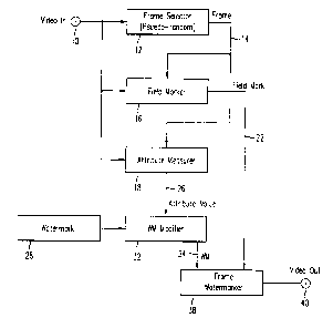
Figure 1 illustrates an exemplary encoder
apparatus located e.g. at a cable television system
"head end." The video program, prior to cable
transmission to the subscribers, is applied at input
terminal 10. Since this is digital video, terminal 10
is typically a multi-line (bus) connector. A frame
selector 12 randomly or pseudo-randomly selects
particular fields or frames, as described above, for
encoding, and provides an indication of each selected
field or frame on control line 14. In response, field
marker circuit 16 marks each frame so indicated in the
video. Control line 14 is also coupled to attribute
measurement circuit 18 which also receives the incoming
video and calculates (measures) the attribute of the
selected fields or frames. The measured digital
attribute value is coupled on lines) 26 to watermark
modifier circuit 32. Element 32 receives the
conventional watermark from a conventional watermark
generator 28 and modifies it with the 4-bit attribute
value. The so-modified watermark is coupled to frame
watermarker circuit 38 which writes the modified
watermarks to each of the fields or frames carrying the
field marker, supplied on line 22. The watermark video
is then output on terminal 40 to the cable (or other)
distribution network. It is to be understood that some
of the elements of Figure 1 (and also Figure 2) are
circuitry and others represent circuitry or functions
carried out e.g. in a programmed microprocessor.
-12-
CA 02305254 2000-04-04
WO 99/18723 PCT/US98/21036
Reading Operation In a Compliant Recorder
1. During the recording process, on detecting a
field marker of the type described above in the
received video program, the compliant recorder/player
measures and stores the attribute of that field or
f rame .
2. The recorder/player compares the measured
attribute to the attribute value decoded (extracted)
from the watermark. The comparison is made only if the
10 watermark detector in the recorder/player first
concludes with high confidence that it has correctly
decoded (verified) the watermark.
3. If the two attribute values match, recording
is allowed to continue. A match does not require
15 identical values, but may allow for some inaccuracies
of measurement, i.e. have some tolerance. If the two
attribute values fail to match, or if periodic field
markers are absent from a copy-once designated program,
recording is disabled.
20 4. The recorder deletes all field markers during
its recording process. Alternatively, a "decoy" field
marker is applied to a field whose attribute differs
markedly from that carried by the watermark, but this
extra step may not be necessary. Simply deleting all
25 field markers should suffice. Deleting the field
markers advantageously obviates the need to modify the
video in order to force a different attribute
measurement during a subsequent recording attempt.
An exemplary compliant recorder is shown in
30 Figure 2; it is complementary to the Figure 1 encoder.
-13-
CA 02305254 2000-04-04
WO 99/18723 PCT/US98/21036
The input digital video, carrying the field markers and
watermarks, is applied at input terminal 46 to field
marker detector 48 which detects each field marker and
outputs an indication of the marked frames on control
line 50 to an essentially conventional watermark
detector/verifier 54. Verifier 54 checks for the
presence of the copy-once bit and conventionally
verifies the watermark. The 4 attribute bits are then
extracted from the verified watermark by extractor 56
l0 and passed on line 62 to comparator 68. Attribute
measurement circuit 58 also receives the input video
and in response to the signals on line 50 measures
(calculates) the predetermined attribute of the marked
frames as indicated on control line 50. The measured
attribute value is coupled to comparator 68 on line 64.
If comparator 68 finds a match, only then is otherwise
conventional recording circuitry 70 enabled.
(Recording circuitry is a conventional digital video
tape or disc recorder.) Coupled to recording circuitry
70 is field marker stripper circuitry 72 and a circuit
74 to change the copy-once bit to the copy-never value
during recording.
Protocol Security
For a "hacker" (copyright infringer) to defeat
this system, i.e. to modify a first generation
legitimate video recording so that it is capable of
being recopied by compliant recorders, he must do the
following (or a process equally complex). First,
during playback of the first (legitimate) recording, he
measures and stores the attribute of every field and
-14-
CA 02305254 2000-04-04
WO 99/18723 PCT/US98/21036
decodes the watermark. Then, he adds a field marker to
a field whose attribute agrees with that carried by the
watermark.
This "hack" requires many seconds of video delay
at MPEG-2 (compressed video) rates, a watermark reader
and an attribute measuring system. (The video being
copied is typically in MPEG-2 compressed form.) Further
detail is provided below.
The present process therefore easily meets the
goal of preventing "hacking" by most people, especially
considering the minimal rewards to be derived from
hacking this part of the typical overall
copy-protection system. A copy-once scheme need not be
as "hack-proof" as is the basic watermark, because
programs labeled "copy-once" will usually by their
nature be less valuable to the copyright owner than
"copy-never" programs. In any case, a hacker wanting
several copies could simply (and arguably legitimately)
make them in parallel from the copy-once original video
program.
Attribute Requirements
The ideal image attribute in accordance with the
invention is:
1. Measurable in a consumer-type digital video
recorder with minimal added circuitry.
2. Relatively immune to the usual video level
errors: non-linearity, noise, tilt, frequency
distortion, quantization and compression artifacts
etc., found in various analog and digital transmission
systems.
-15-
CA 02305254 2000-04-04
WO 99/18723 PCT/US98/21036
3. Such that a hacker could not easily modify a
video signal to force a particular attribute value
without seriously degrading the entertainment value of
the program.
One may be able to dispense with this third
requirement, since in the context of the present copy-
once protocol, it may not make the hacker s job
materially more difficult.
Examples of Attributes
First Example: The average D.C. voltage values of
separate regions of the selected video frame are added
and subtracted in a manner likely to generate a large
attribute value for typical video images. The sizes
and locations of the image regions are chosen to
maximize immunity to tilt, noise and distortion. The
resultant value is divided by the average D.C.
amplitude value of the video frame, to eliminate
attribute measurement errors that might be caused by
video gain discrepancies in intervening hardware
devices or in the transmission path.
Second Example: This is a specific implementation
of the above first example for MPEG compresses video.
Consider an 8 x 8 pixel MPEG-2 macro-block grid
symmetrically disposed about the center of the video
frame. Imagine each macro-block to be colored black or
white in the traditional "checkerboard" pattern. The
attribute is equal to [the sum of all of the D.C. terms
of the white blocks minus the sum of all of the D.C.
terms of the black blocks] divided by the sum of the
D.C. terms of all of the blocks.
-16-
CA 02305254 2000-04-04
WO 99/18723 PCTNS98/21036
Field M,~rkers - Examples
First field marker example: The first 1.5
microseconds of the first horizontal scan line of every
video field (or frame) is set to 25% of video gray
level. Like the other field markers described here,
this marker is located in the overscan part of the
video frame, so as not to be visible on a television
set. (This location is not, however, limiting.) To
mark a specific field, an e.g. 2.5 MHz sine wave at 50
IRE units peak to peak is added to this gray level.
This field marker can be detected reliably even
after passage through a poor quality cable television
channel. However, advantageously it will not survive
passage through a VHS or 8mm VCR's (video cassette
recorder) signal processing and recording circuitry,
though it will survive S-VHS recording. This is
because this field marker is filtered out by the chroma
comb filter in the VHS or 8 mm VCR. Thus, after
recording and playback by a VHS or 8mm VCR, the field
20 markers are effectively eliminated, thereby prohibiting
second generation copying by a compliant recorder.
Second Example: This example is operable for e.g.
VHS, S-VHS and 8mm VCRs. The first 1.5 microseconds of
the first two horizontal scan lines of every field (or
25 frame) is set to the 25% gray level. To mark a
specific field, a subcarrier-frequency sine wave at 50
IRE units peak to peak is added to this gray level,
such that its phase with respect to synchronization is
the same on both scan lines, (unlike a normal chroma
30 signal whose phase reverses on alternate scan lines.)
-17-
CA 02305254 2000-04-04
WO 99/18723 PCT/US98/21036
This marker can be detected reliably even after
passage through a poor quality cable television
channel. However, it will not survive passage through
any consumer-type VCR's chroma filter. On playback,
5 the VCR's comb filter will reduce the chroma on scan
line 1 to 25 IRE units and on scan line 2 to zero. The
field marker detector in a compliant recorder is set to
detect this signal on scan line 2 only. Thus after
recording and playback by an analog VCR, the field
markers are effectively lost, thereby prohibiting
further copying of the video by a compliant digital
recorder.
Third Example: This field marker is operable for
VHS, S-VHS and 8mm VCRs. It begins with the selection
of a 24x4 pixel block in e.g. the bottom left corner of
the video field (or frame). The next step is to
replace the chrominance values within the 24x4 pixel
block with a fixed pattern marker, e.g. with
alternating blue and yellow values. This marker must
20 survive MPEG compression so as to be detected reliably
even after passage through a poor quality cable
channel. However, it must not survive passage through
any consumer type VCR's chroma filter. The field
marker detector in a compliant recorder is set to
25 detect this signal on scan line 2 only. Thus after
recording and playback by a VCR, the markers are
effectively lost, thereby prohibiting second generation
copying by a compliant recorder.
In light of the added protection afforded to copy
30 right owners, using VCR-erasable markers appears to be
-18-
CA 02305254 2000-04-04
WO 99/18723 PCT/US98/21036
a worthwhile enhancement to the present copy-once
system.
Some of these marking principles may be subject to
minor modifications to be fully compatible with MPEG
compression. In light of the added protection afforded
to video material, they appear to be a worthwhile
enhancement to the present copy-once system.
Additional Embodiment Frame Marker and Watermark .
1. In another embodiment, for encoding, a frame
(or field) marker is added pseudo-randomly to a
particular video frame, in e.g. each 4 second long
window. The frame marker is such (as described above)
that it is automatically removed by a VCR. (An example
of such a marker is fixed D.C. chroma values - both
CRed and CBlue on the first line of the first
macroblock). For the marked frame, an attribute value
is calculated and saved.
2. The 4 attribute bits of the watermark are
modified at a pseudo-random position in the following
e.g. 2 seconds window to equal the attribute value of
the previous marked frame.
3. During encoding, steps 1 and 2 are repeated
throughout the video program.
4. When later recording a copy-once program, as
above the frame marker is removed.
In addition to the regular watermark bits carried
conventionally in the low and medium MPEG DCT
coefficients, and just for copy-once, this embodiment
adds 4 extra authorization bits to be carried by some
-19-
CA 02305254 2000-04-04
WO 99/18723 PCT/US98/21036
of the high frequency MPEG DCT coefficients. If a
copy-once state is detected from the regular watermark
bits, the recorder checks if the 4 extra bits are
present; if not, the recorder does not copy. If they
5 are present, the compliant recorder adds sufficient
noise before making the copy. This removes the 4 extra
bits, removing the copy authorization.
One advantage of this approach is that
conventional (non-compliant) VCRs (having no copy
10 control systems) will remove the extra authorization
bits automatically, making the output non-recordable by
compliant (digital) recorders.
In this embodiment, the watermark includes two
distinct portions, called WM1 and WM2. WM1 contains a
15 payload of 8 bits, and is difficult to remove without
degrading the picture quality. The payload bits are
spread over low/mid/high MPEG DCT coefficient
frequencies in macroblocks.
WM2 is e.g. a fixed 4-bit pattern or a CRC
20 (cyclical redundancy check) value of the payload bits.
WM2 is easy to remove, because the WM2 bits are spread
over only the high frequencies and can be erased with a
low pass or other filter. WM2 survives 4.2 MHz
transmission, but not 2.5 MHz VHS recording. WM2 may
25 have most of its energy spread horizontally in
macroblocks, so that it is easy and inexpensive to
erase or to render invalid. For greater robustness,
the optional CRC (4 bits) is used.
The "WM2 erase" circuitry in the compliant
30 recorder erases WM2 using a low pass filter or other
-20-
CA 02305254 2000-04-04
WO 99/18723 PCT/US98/21036
filter on the video data; thus the required circuitry
is minimal. The cost to add WM2 detection circuitry to
the WM detect circuitry is very small because the WM2
detection circuitry reuses most of the WM1 detection
logic.
Figure 3 shows the states for this embodiment. In
Figure 3, the content of each watermark field is
indicated for WM1 and WM2 along the top line of each
column, with the associated action performed by a
compliant recorder/player in the remainder of the
column. The upper half of Figure 3 is the simpler
version of this embodiment; the lower half is the more
complex version with the CRC. In both versions,
copying is permitted only when WM1 is present with the
copy-once bit set, and WM2 is valid (verified).
Defeat Process and Apparatus
In addition to the copy-once embodiments described
above, a method as described above to defeat the
present copy-once processes is shown in Figure 4, which
depicts graphically both the defeat process and
equipment. "Defeat" means providing a recording which
may be in turn be copied; of course this violates the
intention of the present copy-once system. Hence the
present defeat method and apparatus normally would not
be made available commercially by recorder
manufacturers, but are disclosed here for completeness.
(Use of such a defeat method or apparatus typically
would involve copyright infringement.)
Several conventional elements are illustrated in
Figure 4, which include the conventional cable set top
-21-
CA 02305254 2000-04-04
WO 99/18723 PCT/US98/Z1036
device ("box") 100 which is connected to a cable
television cable 102 and sits "on top" of the
consumer's television set (not shown). In this case a
compliant recorder 106, which is a digital video
5 recorder which includes the features of Figure 2, is
connected to the set top device 100. A person who
desires to defeat the present copy-once process couples
a defeat "black box" 104 between his cable set top
device 100 and his compliant recorder 106. Details of
10 this black box 104 are provided below; the black box
104 houses the defeat circuitry.
In step 1 in Figure 4, a video copy-once protected
program, including field markers, is received via cable
102 at the set top device 100 and is transmitted, via
15 the black box 104, to the compliant recorder 106. The
black box 104 includes circuitry which adds a "tag" (a
special field marker) to the first video frame having a
detected (original) field marker. (The black box 104
includes its own field marker detector like the Figure
20 2 device.) This tag has particular characteristics
described below. The black box 104 then stores in its
internal memory a table of time intervals between the
detected field markers on the video program. This
table provides information on the timing of these
25 original field markers. The video signal, with the tag
added to the first field marked frame, is then coupled
to the compliant recorder 106, which is of the type
shown in Figure 2.
The compliant recorder 106 then makes the
30 permitted copy-once recording onto a first tape (or
-22-
CA 02305254 2000-04-04
WO 99/18723 PCT/US98/21036
disk) 110. As described above, in doing so the
compliant recorder 106 strips off all the original
field markers. However it does not strip off the
tags) added by the black box 104, because these tags
are each a special type field marker, which unlike the
original field markers, is not removed by the stripper
circuitry in recorder 110.
In step 2 shown in the bottom half of Figure 4,
the recorded tape (or disc) 110 is then played on a
player (or recorder) 114. Of course the played video
includes none of the original field markers. This
video is played through the black box 104' which has
been reconfigured to its the play mode. (Black box
104' is otherwise the same as shown in the upper half
of Figure 4 but it is now programmed to be in its play
mode rather than its record mode.) The black box 104'
detects the tags) added by the black box 104 in the
recording step 1 and using the first tagged frame as an
indicator, then reinserts new field markers, of the
type present in the original video material, at the
time intervals indicated by the table previously stored
(in step 1) in the black box 104'.
Thus the output video from the black box 104' is
essentially the same as the original video, including
all of the reinserted field markers. This video can
then be recorded by the compliant recorder 106 which
will output a second generation video recording on a
second tape or disc 116 again having no field markers
but still being viewable (but not copiable). Hence by
the method of Figure 4, one may provide a second
-23-
CA 02305254 2000-04-04
WO 99/18723 PCT/US98/21036
generation video recording on tape or disc 116, thus
defeating the present copy-once protection process.
Internal structure of the black box 104, 104' is
shown in Figure 5. The upper half of Figure 5 shows
the black box 104 in its step 1 configuration. The
input video from the set top device 100 is applied to
input terminal 120 and then coupled to frame marker
detector 122 which detects the original frame (field)
markers. Control line 124 communicates an indication
10 of the presence of detected frame markers to a tag
write circuit 128 which thereupon adds tags) at least
to the first field marked frame, and outputs this
tagged video at output terminal 132, which in Figure 4
which is coupled to compliant recorder 106. Similarly,
the indication of the detected frames on line 124 is
communicated to a memory 136 which includes a table for
storing the time intervals between the detected frame
markers.
The bottom half of Figure 5 shows black box 104'
20 in its step 2 configuration. Here the video (from the
player 114) is coupled to the black box input terminal
120 which in turn is coupled to the tag detector 140
which detects the tags inserted by tag write circuit
128. An indication of each such detected tag is
provided on a control line 142, indicating the
particular frames which carries such tag(s). Line 142
controls the frame marker writer 150 which adds frame
markers, corresponding to those in the original video,
at the desired time intervals. These time intervals
are determined by the data previously stored in the
-24-
CA 02305254 2000-04-04
wo r~na~~ rc nus9smo36
memory table 136 which in this case is read out on
control line 146 to control when the frame marker write
circuit 150 actually adds the frame markers.
Then the video with the new frame markers inserted
by frame write circuit 150 is coupled to the black box
output terminal 132, which in turn is coupled (in
Figure 4) to the input terminal of compliant recorder
106. This is an illustrative version of such a black
box and is not limiting.
Construction of such a black box is well within
the skill of one of ordinary skill in the art given the
knowledge provided herein as to the nature of the field
markers, and general knowledge available to one in
video technology. The black box is essentially a
digital device which has the functions of adding the
tag to particular video frames, sensing the original
field markers, and recording a table of same.
Typically the black box is a microprocessor-controlled
device including memory. The actual circuitry in the
20 black box may take a variety of forms that perform the
above-described functions.
TagcLng For Various Video Delivery Methods
For a copy-once tagging system as described above,
one must consider the process including content
preparation, content delivery, and content
viewing/recording. The following analyzes the process
in term of various video delivery methods: analog cable
and broadcast delivery; digital delivery through the
existing installed base of digital set top devices with
no digital (conventionally designated P1394) output;
-25-
CA 02305254 2000-04-04
WO 99/18723 PCT/US98/21036
digital delivery through the existing installed base of
digital set top devices with digital output; and
digital delivery through new digital set top devices.
For analog cable and broadcast delivery, the
content (programs) is prepared prior to delivery and
the process of copy-once to copy no more transformation
is performed in the recording device and may only occur
in the video domain.
For digital delivery through the installed base of
digital set top devices with no digital (P1394) output,
the content is preferably prepared prior to
authoring/MPEG encoding, but may also be prepared in
conjunction with authoring/MPEG encoding.
Nevertheless, copy-once marking should survive MPEG
encoding/decoding. In this case, the copy-once to copy
no more transformation is also performed in the
recording device and may only occur in the video
domain.
Digital delivery through the installed base of
digital set top devices with digital output is similar,
however the copy-once to copy no more transformation
occurs in the MPEG domain.
Finally, for digital delivery through new digital
set top devices, copy-once marking may also occur in
the set top device itself. In addition, in the case of
a P1394 output, the copy-once to copy no more
transformation may also occur in the set top device as
long as a copy authorization is sent from the set top
device to the decoder.
-26-
CA 02305254 2000-04-04
WO 99/18723 PCTNS98/21036
For analog cable and broadcast delivery, the
present system includes a fixed copy-once/copy no more
watermark and the addition of a frame or field tag
attached to randomly selected video frames or sequence
of video frames to identify copy-once material.
Transformation from copy-once to copy no more is
performed by removal or degradation of the tag. In
addition, in order to provide added security, an
attribute of the tagged frame or sequence of frame is
coded in the watermark. The watermark attribute code is
randomly delayed to provide even higher security.
Examples of attributes include representation of
the video characteristics of the tagged frame(s),
position of the tagged frames) or length of the tagged
sequence (which would be randomly selected to provide
security).
The tags are of the type that are automatically
removed by conventional VCRs and even non-compliant
MPEG encoders. For instance, alternating lines of
complementary colors at relatively low amplitudes (the
tag pattern) would be removed by VHS and MPEG encoders
during field to frame conversion. The tag is e.g.
positioned in the lower left end corner (the tag area
being e.g. 64 pixels x 4 lines per field) of the video
and invisible on television sets (due to overscan). To
improve security, the tagging process removes chroma in
the tag area on all video frames and adds the tag
pattern to tagged frames. Tag removal is performed
through chroma removal.
-27-
CA 02305254 2000-04-04
WO 99/18723 PCT/US98/21036
In the case of digital delivery through the
installed base of set top devices with no digital
output, the tagging system must be able to survive MPEG
compression/decompression and will likely survive VCR
and MPEG recording unless tagging is performed inside
the encoder itself or the encoding process is
constrained.
In order to maximize the effectiveness of the
copy-once system, two tagging methods are supported by
compliant recorders. The "stronger" tag defined above
is selected for analog systems or for compatible
encoders. A "weaker" tag with a tag pattern of
horizontal cycles of complementary colors at relatively
low amplitudes is selected for incompatible encoders.
For digital delivery through the installed base of
set-top device with digital output, a digital recorder
preferably performs the copy-once to copy no more
transformation at minimal cost.
One approach is to add and remove an additional
tag placed in the bit stream itself. However the
watermark/tag carried in the video data would also be
required to support the video output of the set top
device and the digitally recorded copy would be labeled
copy no more in the bit-stream and copy-once in the
video. This then requires a synchronization system to
be included in every player to ensure that no more copy
be made.
Another more preferable approach is to minimize
the added requirement for tag detection/tag removal.
-28-
CA 02305254 2000-04-04
WO 99/18723 PCT/US98/21036
The conventional steps required to read the watermark
in an MPEG stream are:
- De-multiplex the transport stream.
- Decode video stream down to the I-frame.
- Decode all slices in the I-frame.
- Process all macroblocks (MB's).
- Process all luminance blocks.
Since, in this case only I-frames (this a type of
MPEG frame) are used in the watermark reading process,
the tag detection/removal process should be performed
using I-frames only using the following steps:
- Process tag area chroma blocks for detection.
- Buffer the bit stream and substitute a pre-
computed "no chroma" block bit sequence for the
"tag chroma" block bit sequence in the tag
macroblocks while ensuring that the video buffer
verifier size (vbv) is not affected.
Since tag removal is performed only on I-frames
and on macroblocks, the following issues and
requirements arise.
For non-compatible encoders, there must be a
sequence of tagged frames and it must be long enough to
ensure that one I-frame will be included. It could be
one frame or the distribution of tagged frames should
be such that there is a sufficient number of I-frames
among them. If a tagged frame sequence is used,
attributes of the sequence should be deductible from
the I-frames) attributes. This is better resolved by
using frame position or frame sequence length as an
attribute. In the frame position method, a tagged frame
-29-
CA 02305254 2000-04-04
WO 99/18723 PCT/US98/21036
would carry a specific watermark code and untagged
frames another. Any mismatch between watermark-code
and tag status creates a no-more-copy. In the frame
sequence length method, frame sequence lengths randomly
alternate between 3xD and SxD, where D is some number
larger than the largest allowable group of picture
(GOP) size (maxGOP). In this method presence of a
single tagged I-frame and sequence of I-frames covering
less than maxGOP total frames would indicate no-more-
copy. So would a sequence of I-frames covering more
than D and less than 3D total frames matched with a 5xD
code in the watermark or a sequence of I-frames
covering more than 3D total frames matched with a 3xD
code in the watermark. The later is the preferred
method.
If a tag sequence is used, none of the tags of the
frames preceding the first I-frame in the sequence will
be removed. The position and sequence length methods
described above resolve this. Tag removal from
I-frames must frequently remove tags in other frames in
the GOP. This will occur when no motion occurs in the
tag area and could be improved by forcing motion
vectors to zero in the tag area during encoding. Tag
removal from I-frames must not create significant
artifacts in other frames in the GOP. This could occur
since the tag area could be used to predict any
macroblock surrounding it in subsequent P and B frames.
This is one of the reason why the tag in one embodiment
uses complementary colors. Removal of the tag should
not produce a visible chroma change. Tag removal
-30-
CA 02305254 2000-04-04
WO 99/18723 PCT/US98l21036
through replacement of a precomputed chroma block
implies either removing all chroma in a 54x16 area
creating artifact visible on some televisions or
carrying a bit stream in the user data that would have
to be generated by a compatible encoder.
For compatible encoders, tag generation is
performed by the encoder on I-frames only. Motion
vectors are forced to zero on subsequent P and B frames
and no intra-block coding is allowed on these frames.
Motion prediction for non-tag blocks is forced not to
use the tag blocks.
For digital delivery through new generation
digital set top devices, frame tagging occurs only in
the video output in the same manner ACP is generated.
The pre-watermarked content is tagged (using the strong
tag) by the video encoder using tag position
information carried in the bit stream. On the P1394
side, the set top device enables P1394 output once a
compliant recorder was identified. This system even
allows one to specify whether a copy could be made
through the analog or digital output independently.
Copyright information and related data (tag position)
are carried in the bit stream in the same way ACP
information is currently carried.
Three possible systems are disclosed hereinafter.
All three systems use a common recorder and a common
architecture. No artifact are produced on original
material (so that a program viewer will not see any
effect) or on video copies (as opposed to MPEG copies).
-31-
CA 02305254 2000-04-04
WO 99/18723 PCTNS98/21036
For a copy-once architecture for compatible
encoders, tags are inserted on I-frames only. For non-
compatible encoders, tag sequences of 3 seconds and 5
seconds are randomly added to the video and after a
random Iag time a "tag length identifier" bit in the
watermark is set to 0 for a 3 second sequence, 1 for a
5 second sequence. Another bit (Change Bit) is toggled
every time a new tag sequence is being referenced (thus
reducing the number of watermark to 10). A tag uses
10 horizontal or vertical cycles of complementary colors
at relatively low amplitudes on the 8 bottom lines of
the lower left four macroblocks. An 11th and 12th bit are
used to differentiate between what are here designated
as systems 1, 2 and 3.
15 1. System 1 has analog delivery & digital
delivery with compatible encoder/authoring. In this
system, the vertical cycles are used, allowing removal
of the tag by VHS VCRs and some non-compliant MPEG
encoders. Tag removal is performed by blanking out the
20 bottom eight lines of video on video recorder and the
bottom sixteen lines of video on MPEG recorders.
For compatible encoders, one inserts the tag after
the field to frame conversion, use tags on I-frames
only, forces motion vectors to zero for the bottom
25 macroblocks, forces motion prediction in other
macroblocks not to use the bottom macroblocks and
disallows intra-coding for tag area Macroblocks in P/B
f rames .
2. System 2 has digital delivery without
30 compatible encoder/authoring. In this system, the
-32-
CA 02305254 2000-04-04
WO 99/18723 PCT/US98/21036
horizontal cycles are used. Tag removal in the MPEG
domain is performed by removing the chroma in the tag
macroblocks. Some artifacts may be visible in the tag
area of digitally copied content on certain
televisions. Security of this system may not be as
strong on MPEG copies since a pirate may cue on the
fact that 16 lines of chroma are missing in the tag
area on tagged frames while only eight are missing on
non-tagged frames.
3. System 3 has digital delivery in new
networks. This system is not backward compatible With
systems 1 or 2. However it provides a high quality, low
cost solution for new networks or networks that would
require the use of new set top devices to allow copy-
once.
For video input, upon detection of a copy-once
watermark, the recorder removes the tag by removing the
chroma in the 8 bottom lines of a frame in the tag
area.
For digital input, upon detection of a copy-once
watermark (system 1 or 2), the tag detector identifies
whether system 1 or two is used. For system 1, tag
removal is performed by replacing the bottom slices
with a pre-stored slice (blanking out the 16 bottom
video lines) and padding so as not to affect the vbv.
For system 2, tag removal is performed by replacing the
bottom chroma tag blocks with pre-stored blocks
(removing the chroma from the bottom left 4
macroblocks).
-33-
CA 02305254 2000-04-04
WO 99/18723 PCT/US98/21036
Upon detection of a copy-once watermark system 3,
a copy is made as long as the P1394 authentication
protocol identifies copy-once.
Video Taq (Frame/Field Marker)
The frame or field marker "tag" described above is
a video signal or signal modification inserted into a
video stream, which is essentially transparent to MPEG-
2 compression but which is intrinsically rejected by
(at least) a standard VHS type VCR, and which may be
thereafter read from the video signal to convey
information. The tag is preferably transparent to
MPEG-2 compression so that it may be inserted into the
video prior to the MPEG encoding, thereby requiring no
modification of the MPEG encoder. The information
intended to be conveyed involves the copy protection
status of the associated video; however, other
applications are possible as well, and this type of tag
is not limited to the copy protection field. Other
applications are authentication or data transmission.
One may use a chroma-inversion tag, in which
successive selected lines have a specific chroma
pattern injected or superimposed, such that the
modulated chroma on successive lines is phase-inverted.
The intent is that the comb filter in the VCR cancels
that signal. However the format-required vertical
subsampling of chroma in the MPEG-2 encoding system
requires vertical anti-aliasing filtering. One pattern
essentially consists of a high vertical frequency
transition in the chroma spatial domain, and the MPEG-2
anti-aliasing filter is essentially a vertical low-pass
-34-
CA 02305254 2000-04-04
WO 99/18723 PCT/US98/21036
filter. (Indeed, the architecture of the VCR's comb
filter is structurally identical to the MPEG-2 anti-
aliasing filter, with the anti-aliasing filter
typically having a more complex, lower-frequency cutoff
than does the comb filter.) As such, the anti-aliasing
filter eliminates the inserted chroma pattern just as
does the comb filter; thus the inserted signal
undesirably is lost in all formats of interest.
The baseband chroma bandwidth of the MPEG-2 system
is approximately 1.4 MHz, depending upon
implementation. Figure 6A shows the well known
spectrum of the color-under VHS format video signal.
The baseband chroma bandwidth of a standard VHS VCR is
approximately 300 kHz, again depending upon
implementation. There is therefore a region in the
baseband chroma domain extending from approximately 300
kHz to approximately 1.4 MHz (1.1 MHz bandwidth) in
which a signal will pass through an MPEG-2
encode/decode chain yet will be rejected by a standard
(consumer type) VHS VCR (NTSC or PAL).
It is desirable that the tag signal to be injected
exists entirely and solely in that region, in order
that no component of it shall pass through the VCR's
300 kHz chroma path. The VCR's own chroma-channel
filtering ensures that no component of the inserted tag
signal intrudes into the VCR's luma path.
One embodiment of the tag signal (see Figure 6B
showing the spectrum of the present inserted tag
compared to that of the color-under chroma channel) is
an 844 kHz chroma square wave consisting of a repeating
-35-
CA 02305254 2000-04-04
WO 99118723 PCT/CTS98/21036
horizontal pattern of four consecutive CCIR-601 4:2:0
chroma samples of green followed by four consecutive
chroma samples of magenta. In the video domain, this
is a chroma signal which inverts its phase
approximately every two cycles of chroma (at 3.58 MHz)
and may be regarded as a double-sideband suppressed-
carrier signal having only two spectral components:
one at (3.58 MHz - 844 kHz) and one at (3.58 MHz + 844
kHz). In particular, there are no spectral components
within 300 kHz of 3.58 MHz. Figure 6C shows the
spectrum of the inserted tag compared to the MPEG-2
baseband chroma channel, and Figure 6D shows the
modulated chroma waveform of the injected tag.
Other tag implementations are possible. The
pattern need not be a square wave, although the square
wave is the easiest to generate; it could, for
instance, be a sine wave. Similarly the pattern need
not be at 844 kHz; any frequency which is sufficiently
higher than approximately 300 kHz and lower than
approximately 1.4 MHz will do. An alternative
frequency is 1.125 MHz, which consists of three CCIR-
601 samples of green and three of magenta. Moreover,
the pattern need not be symmetrical nor, indeed, even
repetitive - any pattern or signal whose primary energy
lies below approximately 1.4 MHz but which has no
content below approximately 300 kHz works well; the
choice is made to simplify the implementation.
One method of conveying information with this
signal is to insert tags of several different lengths
such that they can be measured in numbers of I-frames,
-36-
CA 02305254 2000-04-04
WO 99/18723 PCT/US98/21036
and then put in an accompanying video watermark
information representing the length of the tag. The
system then requires that the two match, before
enabling a copy.
5 ~ In order to minimize visibility of a signal such
as this, it is desirable to make its various elements
as small as possible, both horizontally and vertically,
and of such a nature that they tend to disappear
visually. The tag in another embodiment thus consists
of colored small areas alternating both horizontally
and vertically to form a "checkerboard" pattern. The
colors in one embodiment are green and magenta, because
these are complementary colors with very similar
luminance values and the eye tends to spatially average
15 them into a uniform gray; other colors are possible.
The colored areas should be as small as is consistent
with the spatial resolution capabilities of the chosen
format; in the case of MPEG-2 compression the
limitation is the horizontal and vertical anti-aliasing
filters which precede the chroma subsampling which that
format dictates.
Details of this embodiment are implementation-
dependent. For a typical MPEG-2 application, using a
digital anti-aliasing filter with coefficients [-29, 0,
25 88, 0, -29] *256 for both horizontal and vertical
subsampling, one embodiment of the tag signal is
created by applying a sequence of fully-sampled (i.e.
13.5 MHz) pixels consisting of a green pixel, two gray
pixels, a magenta pixel and two more gray pixels to the
indicated anti-aliasing filters. This sequence is
-37-
CA 02305254 2000-04-04
WO 99/18723 PCT/US98/Z1036
duplicated in both the horizontal and vertical
directions to create the desired "checkerboard"
pattern, and is continued in both directions (or
"repeated") for as far as is desirable and useful to
the application at hand.
The individual green and magenta pixels constitute
impulse functions input to the anti-aliasing filters,
and the filter output signal is a sequence of pixels
corresponding to the filter coefficients - that is, a
single pixel output to the indicated filter will result
in an output sequence of pixels with an amplitude
pattern of -29, 0, 88, 138, 88, 0 and -29. The total
output of the filter is the linear sum of its responses
to each of the input pixels. In the embodiment
described above, if a magenta pixel is coded as "-1", a
gray pixel as "0" and a green pixel as "+1", the
steady-state response of the filter to the tag sequence
described above will be ...88, -88, -196, -88, 88, 196,
88, -88, -196, ... which describes chroma sine wave at
1.125 MHz.
The checkerboard pattern is created by arranging
the input signal such that, in any given tagged scan
line, a given pixel conforms to the indicated spatial
pattern. That is, if pixel 20 in line 460 of the input
is green, then pixel 20 in lines 461 and 462 should be
gray, pixel 20 in line 463 should be magenta and pixel
20 in lines 464 and 465 should be gray. Pixels 21 22,
24 and 25 would be gray in all tagged lines, and all
pixels in the tagged portions of lines 461, 462, 464
and 465 would also be gray. The action of the anti-
-38-
CA 02305254 2000-04-04
WO 99/18723 PCT/US98/21036
aliasing filters will then smear the single colored
pixels into the desired sine waves in both the
horizontal and the vertical directions.
This disclosure is illustrative and not limiting;
5 further modifications will be apparent to one skilled
in the art in light of this disclosure and are intended
to fall within the scope of the appended claims.
-39-