Note: Descriptions are shown in the official language in which they were submitted.
CA 02305591 2000-03-30
WO 99/18907 PCT/US98121200
SAFETY SEPARATION SYSTEM
Technical Field
The present invention pertains to a vehicular safety system and method, and,
in
particular, to a vehicular safety system and method for preventing injury to
the passenger
of a motorized vehicle by separating a body support from the ground contacting
assembly
of the vehicle.
Background of the Invention
Vehicles. whether for the transportation of humans or other types of payloads,
may
lack stability, either by design or due to the nature of their use. Many such
vehicles are
particularly susceptible to tipping, whether due to collision, mechanical
failure, sudden
turns, steep inclines, or an encounter with a surface irregularity for which
the mechanism
1 S is incapable of compensating. Indeed, any personal vehicle may tip when
sufficiently severe
surface irregularities are encountered. Under these circumstances, the
occupant or contents
of the vehicle must be protected so that injury does not result from
propulsion of the
occupant toward the ground or other solid obstacle. Unless protected, the
occupant may also
sustain injury due to trauma or crushing if the vehicle, which is relatively
massive, overturns
or is propelled, due to its inertia, into a solid obstacle or on top of the
occupant.
Methods are known for absorbing or diverting kinetic energy inherent in the
motion
of a vehicle to insure that it is not converted to propulsion of the occupant
of the vehicle into
a solid body such as the ground. Common examples are bumpers on cars, which
absorb
kinetic energy in crumpling metal, and airbags, which couple the mechanical
energy of car
passengers into the compression and redistribution of gas in a bag before
enough time has
elapsed for the bodies of the passengers to hit the steering wheel or
windshield of the car
with resulting serious injury.
Other means are known to employ the kinetic energy present in a massive
subcomponent of the vehicle, to inflate a bellows or other cushion to protect
the vehicle
occupants in the case of a head-on collision.
1
CA 02305591 2000-03-30
WO 99/18907 PCT/US98/21200
In an unenclosed vehicle such as a wheelchair, for example, it is often safer
to divert
the passenger from the path of the center of mass of the vehicle than to trap
him between
the mass of the vehicle, moving with its attendant momentum, and its ultimate
position of
repose, such as at a solid surface after a crash.
Summary of the Invention
In accordance with one aspect of the invention, in one of its embodiments,
there is
provided a safety mechanism for protecting a passenger of a vehicle in a
situation wherein
the vehicle undergoes undesirable acceleration. The vehicle is one which has a
ground
contacting assembly and a body support with a center of gravity (CG). The
safety
mechanism has a connector for coupling the body support and the ground
contacting
assembly. It also has a release for decoupling the motion of the CG of the
body support
along at least one axis from the motion of the ground contacting assembly. An
actuator for
unleashing the release in response to an undesired acceleration of the vehicle
is also
provided.
In accordance with an alternate embodiment of the invention, the connector
allows
free motion of the body support with respect to the ground contacting
assembly, and may
be a pneumatic cylinder or a slide track. The safety mechanism may also have a
rotary
actuator, including a motor, for rotating the body support with respect to the
ground
contacting assembly such as to counteract the effect of a roll of the ground
contacting
assembly on the orientation of the body support with respect to a vertical
direction.
In other embodiments of the invention, the safety mechanism has a pilot wheel
assembly coupled to the body support. The pilot wheel assembly may include at
least one
wheel, and a self-leveling mechanism. The release may include a means for
storing
mechanical energy, such as a spring or coil spring, coupled to at least one of
the ground
contacting assembly and the body support such that the mechanical energy is
used to
decouple the motion of the CG of the body support from the motion of the
ground
contacting assembly.
In accordance with further embodiments of the invention, the safety mechanism
may
have a reservoir of mechanical energy coupled to at least one of the ground
contacting
2
CA 02305591 2000-03-30
WO 99/18907 PCT/US98/21200
assembly and the body support such that the mechanical energy is used to
decouple the
motion of the CG of the body support from the motion of the ground contacting
assembly.
In accordance with another aspect of the invention, a method is provided for
protecting a passenger of a vehicle having a ground contacting assembly and a
body support
in a situation wherein the vehicle undergoes undesirable acceleration. The
method has the
steps of sensing the undesired acceleration and decoupling the motion of the
center of w
gravity of the body support from the motion of the ground contacting assembly
with respect
to at least one axis.
Brief Description of the Drawings
The invention will be more readily understood by reference to the following
description, taken with the accompanying drawings, in which:
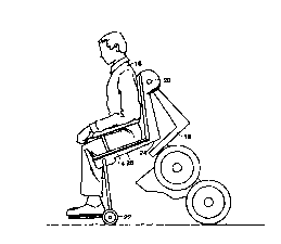
FIG. 1 is a side view of a prior art wheelchair-type vehicle of the type in
which an
embodiment of the invention may be advantageously employed.
FIG. 2 is a side view of the wheelchair-type vehicle of FIG. 1 shown in an
early
stage of a forward tip.
FIG. 3A is a side view of the wheelchair-type vehicle tipping as in FIG. 2
employing an embodiment of the current invention showing partial separation of
the body
support forward of the ground contacting assembly.
FIG. 3B is a perspective view from the side of a wheelchair-type vehicle
employing
an alternate embodiment of the current invention showing partial separation of
the body
support from the ground contacting assembly along a slide track.
FIG. 4 is a side view of the wheelchair-type vehicle tipping as in FIG. 2
employing
an embodiment of the current invention showing a further stage of separation
of the body
support forward of the ground contacting assembly.
FIG. 5 is a side view of the wheelchair-type vehicle tipping as in FIG. 2
employing
an embodiment of the current invention showing a final stage of separation of
the body
support forward of the ground contacting assembly.
FIG. 6 is a perspective view of the wheelchair-type vehicle tipping as in FIG.
2
employing an embodiment of the current invention showing a final stage of
separation~of
the body support forward of the ground contacting assembly.
3
CA 02305591 2000-03-30
WO 99/18907 PCT/US98/21200
FIG. 7 is a side view of the wheelchair-type vehicle of FIG. 1 shown at an
instant at
which a ground obstacle is encountered.
FIG. 8 is a side view of the wheelchair-type vehicle tipping as in FIG. 7
employing
an embodiment of the current invention showing partial separation of the body
support
forward of the ground contacting assembly.
FIG. 9 is a side view of the wheelchair-type vehicle tipping as in FIG. 7
employing w
an embodiment of the current invention showing a further stage of separation
of the body
support forward of the ground contacting assembly.
FIG. 10 is a side view of the wheelchair-type vehicle tipping as in FIG. 7
employing
an embodiment of the current invention showing a final stage of separation of
the body
support forward of the ground contacting assembly.
FIG. 11 is a front view of the vehicle of FIG. 1, shown approaching a step or
curb.
FIG. 12 is a front view of the wheelchair-type vehicle tipping as in FIG. 11
employing an embodiment of the current invention showing partial separation of
the body
support sideward of the ground contacting assembly.
FIG. 13 is a front view of the wheelchair-type vehicle tipping as in FIG.11
employing an embodiment of the current invention showing a further stage of
separation of
the body support sideward of the ground contacting assembly.
FIG. 14 is a perspective view of the wheelchair-type vehicle employing an
embodiment of the current invention in the intermediate stage of a sideward
tip of FIG. 13.
FIG. 15A is a front view of the wheelchair-type vehicle tipping as in FIG. 11
employing an embodiment of the current invention showing ground contact of a
pilot wheel.
FIG. 15B is a perspective view of the wheelchair-type vehicle employing an
embodiment of the current invention in the stage of a sideward tip of FIG. 15.
FIG. 16 is a side view of the wheelchair-type vehicle of FIG. 1 shown in an
early
stage of a forward fall down a flight of stairs.
FIG. 17 is a side view of the wheelchair-type vehicle tipping as in FIG. 16
employing an embodiment of the current invention showing partial separation of
the body
support forward of the ground contacting assembly.
4
CA 02305591 2000-03-30
WO 99/18907 PCT/US98/Z1200
FIG. 18 is a side view of the wheelchair-type vehicle tipping as in FIG. 16
employing an embodiment of the current invention showing a further stage of
separation of
the body support forward of the ground contacting assembly.
FIG. 19 is a side view of the wheelchair-type vehicle tipping as in FIG. 16
employing an embodiment of the current invention showing a final stage of
separation of
the body support forward of the ground contacting assembly. w
Detailed Description of Preferred Embodiments
The present invention provides a mechanical strategy for handling the fall in
any
direction of a personal vehicle, such as a wheelchair-type vehicle.
Referring now to FIGS. 1 through 19, wherein like elements are designated by
identical numerals, views are shown of a personal vehicle, designated
generally by numeral
10, in progressive stages of various tipping motions. An example of such a
vehicle is the
wheelchair-type vehicle described in copending U.S. patent application, Serial
No.
08/250,693, filed May 27, 1994 for an invention by Kamen et al., which is
herein
incorporated by reference. The present invention is applicable to motorized
personal or other
vehicles, such as the vehicle described in the application of Kamen, and to
unmotorized
personal vehicles as well. Referring, particularly, to FIG. 1, vehicle 10 is
shown, by way of
example, as supported on a pair of laterally disposed wheels 12 (of which one
is visible in
FIG. 1 ) that provide ground contact for vehicle 10. While the invention will
be described
with reference to the wheelchair-type vehicle shown in FIG. 1, it is to be
understood that
vehicles with other configurations, bearing other numbers of wheels, and used
for other
purposes may similarly benefit from the safety mechanism which is the subject
of the
present invention.
Vehicle 10, broadly speaking, has two primary functional parts: a body support
14
which may be in the form of a seat or otherwise, for carrying a passenger 16,
and a ground
contacting assembly 18 which includes wheels 12 and bearing mechanisms and
motor drives
(not shown), if present, associated with the wheels. In conventional vehicles,
and under
ordinary circumstances of operation, body support 14 is coupled to ground
contacting
assembly 18 in a fixed manner, and passenger 16 is transported through
locomotion across
the ground of ground contacting assembly 18. The strategy employed by the
present
5
CA 02305591 2000-03-30
WO 99/18907 PCT/US98/21200
invention in case of mishap is to decouple passenger 16, along with body
support 14, from
being constrained to follow the motion defined by coupling of body support 14
to ground
contacting assembly 18. Prior to a mishap, which may include an encounter with
an
obstacle, sudden turning resulting in instability, mechanical or electrical
failure, or other
event, passenger 16 is traveling with motion parallel to the ground, and in a
desired body
orientation, ordinarily seated. To avoid injury to the passenger, it is
desirable to maintain
this orientation, to the extent possible, independent of subsequent tumbling
of the ground
contacting assembly 18. In order to bring about the desired separation of the
post-mishap
inertial motion of the body support 14 from that of the ground contacting
assembly, a
physical decoupling of the body support from the ground contacting assembly is
effected
with respect to some or all degrees of freedom. The separation is 'passive' in
the sense that
the kinetic energy of the body support and passenger are used to effect the
decoupling, or,
alternatively, the separation may be powered or assisted by mechanical or
other means.
Examples of some methods of decoupling are discussed in the description which
follows.
Referring now to FIG. 2, a side view is shown of vehicle 10 in the initial
stages of
a tip, shown, in this case and by way of example, in a forward direction. Body
support 14
is shown, again by way of example, as a chair-type configuration in which
occupant 16 is
seated, however other modalities of support are possible, and occupant 16
might be
recumbent or in another position. FIGS. 2-6 represent a time-series of side
views of vehicle
10 as it is tipping. Such a tip might arise due to a sudden turn or a
mechanical failure of the
system which ordinarily maintains vehicle 10 in an upright position, or due to
an encounter
with a surface irregularity or obstacle for which the vehicle and/or the
driver is incapable
of compensating. One of the embodiments of the present invention is shown in
FIG. 3A,
where vehicle 10 is shown in a further stage of a forward tip. In the depicted
embodiment,
body support 14 is coupled to ground contacting assembly via connector 20,
which is
shown, by way of example, as a pivot, located such that the inertial motion of
body support
14 in a forward direction causes the body support and passenger 16 to swing
clear of ground
contacting assembly 18 after a mishap. A spring, such as a coil spring
configured about
pivot 20 may be employed to assist the separation of body support 14 from
ground
contacting assembly 18. A "release," as used in this description and in the
claims hereto
appended, refers to any release mechanism for enabling the separation of body
support 14
6
CA 02305591 2000-03-30
WO 99/18907 PCT/US98/21200
from ground contacting assembly 18. Many such mechanisms, such as a latch
employing
a locking mass displaced from a locking position upon inertial acceleration,
are known to
persons skilled in the mechanical arts. Additionally, electronic sensors may
be used to
unleash the release which assists in the decoupling of the body support 14
from ground
contacting assembly 18, after an initial tip is sensed. In addition to
assisting the separation
of body support 14 from ground contacting assembly 18, a spring coupled
between body
support 14 and ground contacting assembly 18 serves, once expanded, as a
damper to absorb
the kinetic energy of the body support 14 thereby cushioning the effect of the
mishap on
passenger 16 and vehicle.
Pivot 20 is shown as an example of many mechanisms whereby body support 14 may
be coupled to ground contacting assembly 18 so as to permit subsequent
decoupling of
motion in the event of mishap. In other embodiments of the invention,
identical relative
motion of body support 14 with respect to ground contacting assembly 18 as
that shown in
FIG. 3A is achieved by coupling a point 24 on bottom surface 26 of body
support 14 to a
slide mechanism 28 (shown in FIG. 3B). Such an embodiment is described with
reference
to FIG. 3B wherein body support 14 separates from ground contacting assembly
18 by riding
on slide mechanism 28 which constrains the motion of body support 14 along at
least one
axis. By virtue of this arrangement, body support 14 can be said to be
virtually pivoted about
a point above the respective centers of mass of both body support 14 and
ground contacting
assembly 18. The slide mechanism constrains body support 14 to move in a
forward
direction, with reference to the driver, and may be realized by means of a
slide, or a rodless
pneumatic cylinder, or in other ways, as are known to persons skilled in the
mechanical arts.
In an alternate embodiment, the mechanism providing coupling between body
support 14 and ground contacting assembly 18 is a universal joint, thereby
decoupling the
motions of body support 14 and ground contacting assembly 18 after a mishap to
operate,
as well, when the unintended acceleration of ground contacting assembly 18 is
in a sideward
direction. Such an arrangement prevents torques from being transmitted from
the
surroundings to the body support 14.
Referring, again, to FIG. 3, it is apparent that operation of the mechanism
separating
the motions of body support 14 and ground contacting assembly 18 after a
mishap permits
passenger 16 to remain substantially in a proper orientation, with head up and
legs down,
7
CA 02305591 2000-03-30
WO 99/18907 PCT/US98/21200
and avoids entrapment of passenger 16 with ground contacting assembly 18. In a
preferred
embodiment of the invention, body support 14 is provided with one or more
pilot wheels
22 to allow continued forward motion of body support 14 and to prevent tipping
about a
fixed point in contact with the ground.
S FIG. 4 shows vehicle 10 in a subsequent stage of separation of body support
14 from
ground contacting assembly 18, while FIG. 5 shows vehicle 10 after ground
contact
assembly 18 has fully overturned, while passenger 16 remains protected by body
support 14
and in a substantially upright position. FIG. 6 is a perspective view of
vehicle 10 in the same
state of repose as depicted from the side in FIG. 5.
Refernng now to FIG. 7, vehicle 10 is shown in an upright orientation
associated
with ordinary locomotion, at an instant at which wheel 12 encounters a ground
obstacle 30.
While vehicle might be designed to overcome the obstacle, in the event of the
incapacity of
the vehicle to overcome the obstacle, the response of an embodiment of the
present
invention will be described with reference to FIGS. 8-10. Referring, more
particularly, to
FIG. 8, by way of example, vehicle 10 is shown in an early stage of separation
of body
support 14 from ground contacting assembly 18 by means of opening about pivot
20. Pilot
wheel 22 is shown having made contact with ground obstacle 30 to provide
support against
tipping for body support 14. A later stage of separation of body support 14
from ground
contacting assembly 18 is shown in FIG. 9, while FIG. 10 shows ground
contacting
assembly 18 fully tipped, while passenger 16 remains in a substantially
upright and
protected position by virtue of the operation of the invention to separate the
motion of body
support 14 from that of ground contacting assembly 18.
Referring now to FIGS. 11-15, in which vehicle 10 is shown responding to a
sideward tip in accordance with the invention. Refernng more particularly to
FIG. 11,
vehicle 10 is shown approaching a lateral surface irregularity 32 which may be
a curb or a
step, for example. FIG. 12 shows ground contacting assembly 18 in an early
stage of lateral
tipping due to surface irregularity 32. The term "roll angle" 40 as used in
this description
and in the appended claims is defined to refer to the angle between the
vertical axis of
passenger 16 (i.e., a line parallel to the spine of the passenger) and an axis
44 parallel to a
plane containing a wheel 12 of ground contacting assembly 18. Roll angle 40
may be
corrected, in accordance with a preferred embodiment of the invention, by
allowing free or
8
CA 02305591 2000-03-30
WO 99/18907 PCT/US98/21200
mechanically driven rotation of body support 14 about an axis perpendicular to
axes 42 and
44. Equivalently, roll angle 40 may be corrected to maintain passenger 16 in a
substantially
upright position by other combinations of motion known to persons skilled in
the
mechanical arts, such as by means of a driven swivel of body assembly 14 about
axis 42
parallel to the spine of passenger 16 coupled with translation of the point of
contact between
body assembly 14 and the plane of ground contacting assembly 18 which is
perpendicular
to axis 44. In a preferred embodiment of the invention, the swivel of body
assembly 14
about axis 42 is driven by a motor or other actuator (not shown) which is part
of a control
loop in which the torque applied about axis 42 is governed by a controller on
the basis of
the sensed deviation of axis 42 from the true vertical axis
FIG. 13 shows vehicle 10 in a further stage of lateral tipping, with wheels 48
and 50
in contact with the underlying surface at different vertical levels, and with
the position of
body support 14 and passenger 16 corrected in accordance with an embodiment of
the
invention, as described above. FIG. 14 is a perspective view of vehicle 10 in
the later tip of
ground contacting assembly 18 shown in FIG. 13.
FIG. 15A shows a side view of vehicle 10 in a later stage of a lateral tip,
where pilot
wheel 22 has contacted the ground to provide support against tipping for body
support 14.
FIG. 1 SB shows a perspective view of vehicle 10 in a final state of repose
after the sideward
tip of FIG. 15A. While ground contacting assembly 18 has rotated along path
52, the inertia
of body support 14 has maintained passenger 16 in an upright and protected
position, and
at rest, with pilot wheel 22 supporting body support 14 on the ground. In an
alternate
embodiment, body support 14 may have a plurality of pilot wheels 22 or
casters, with a
mechanical, hydraulic, or other interconnecting link to provide for force-
leveling or
self leveling so that after a mishap, body support 14 may be supported on a
plurality of pilot
wheels 22, even when the ground surface is uneven.
FIGS. 16-19 show vehicle 10 responding to a forward fall down a flight of
stairs 56
by separation of body support 14 from ground contacting assembly 18 in
accordance with
an embodiment of the invention. FIG 16 shows the initial stage of the forward
fall, prior to
separation of body support 14 from ground contacting assembly 18. FIG. 17
shows the
separation of body support 14 from ground contacting assembly 18 about pivot
20, while
FIG. 18 shows a further stage of separation, and FIG. 19 shows the final state
of repose of
9
CA 02305591 2000-03-30
WO 99/18907 PCT/US98/21200
vehicle 10, with passenger 16 shown supported by body support 14 in a
substantially upright
and protected orientation, despite the complete overturn of ground contacting
assembly 18.
The described embodiments of the invention are intended to be merely exemplary
and numerous variations and modifications will be apparent to those skilled in
the art. All
such variations and modifications are intended to be within the scope of the
present
invention as defined in the appended claims.