Note: Descriptions are shown in the official language in which they were submitted.
CA 02305664 2000-03-28
WO 99/16672 PCT/US98/20409
1-
METHOD & APPARATUS FOR PALLETIZING
ELONGATED BAGS OF CONTAINER ENDS
Related Applications
This application is related to U.S. Provisional Patent
Application S.N. 60/060,518 filed 30 September 1997 entitled
Bagger & Palletizer for Can Ends, and to copending International
Patent Application No. PCT/US98/ (Docket DSG 006 P2) entitled
Bagger filed on the same date as this application.
Technical Field
This invention relates to methods and apparatus for
packaging can ends, e.g. disc-like end units which have a
preparatory curl on their edge and which may also have attached
easy-open tabs. In practice such apparatus is often called a
bagger, since the preferred manner of packaging the ends places a
stack (usually called a "stick") of the ends in a tubular bag
which is then folded closed at its initially open end. The
invention disclosed relates to methods and apparatus for
assembling and placing the sticks on pallets.
Background Art
In the early 1970s can ends were placed manually into bags,
and the bags were loaded manually into pallet for use at
filing/~losing machinery. In the mid-1970s semi-automatic
bagging equipment was introduced in an effort to keep up with the
increased output of newer conversion presses, and that
2,f development led to automatic bagging machines, which were first
introduced in the mid-1980s. Some of the impetus for this
development was the monotony of repeated manual operations, which
also appeared to be the cause of repeated strain to the hands of
those doing the bagging.
Those automatic machines formed a "stick" of ends and then
packaged them 1) by wrapping them from a coil or reel of paper or
plastic, or 2) placing the sticks into preformed bags. It was
found that kraft paper was the preferred wrapping material since
it can be recycled, and since it will "breathe" to void fumes
CA 02305664 2000-03-28
WO 99/16672 PCT1US98/20409
2-
which may linger with the stick of ends from synthetic sealing
compounds applied to the ends in an earlier operation, or to void
moisture which may linger from water based compounds.
In the early patent prior art, the disclosures in US patents
3, 337, 064, 3, 417, 853, 3, 545, 631 and 3, 618, 530 are representative
of systems which use a pneumatic or similar input conveying
system for the individual can ends, and troughs or the like for
gathering the ends in a face to face on-edge stack. Mechanical
feeding mechanisms engage the curl edges of the generally
vertically positioned ends and move them into the input or
receiving end of a stack forming in a trough, then the ends are
supplied to a filling and closing (end curling) machine.
Wrapping a stack is not disclosed, and the filled trough is
intended to function as a reservoir for smooth steady supply of
ends to the closing machine.
In US patents 3,722,741, 4,000,709, 4,537,550, 4,676,708 and
5,335,810 more sophisticated buffer systems for stacks of ends
are disclosed, wherein the stacks are separated according to a
count of stacked ends, and those stacks are loaded into
successive vertically arranged carriers on an endless, carrousel
type conveyor which supplies the stacks to a closing machine.
US patents 3,878,945, and its various divisions Nos.
3,962,845, 3,971,189, 4,051,965, and US patent 5,119,617, all
disclose features of an automatic bagging system in which ends
are supplied to a gathering and counting deice which separates
ends into stacks (or "sticks"), wrapping devices for loading the
stacks into individual bags, and mechanism for loading the
wrapped stacks onto pallets.
US patent 4,364 relates to a conveying improvement for
gathering ends, providing temporary spacing thereof to facilitate
curing of previously applied end seam compound. US patent
4,655,350 discloses an improvement for detecting and removing
ends which have been reversed face-to-back (e.g. public to
product sides) in the formation of a stack. US patent 4,742,669
CA 02305664 2000-03-28
WO 99116672 PCT/US98I20409
3-
discloses and improved end counting device in the end counting
and stack forming systems. US patent 5,005,340 discloses a
system for inspecting an assembled stack of ends. US patent
5,372,245 discloses an improved drive for an in-feeding array of
assembled ends. US patent 5,524,947 discloses an improved
mechanism for picking and placing stacks (also called "sticks")
of ends in the bagging and palletizing process.
US patents 4,537,010 and 5,372,473 disclose more advanced
devices for handling bagged stacks of ends and placing them into
pallets.
Thus, prior art automatic bagging machines allow lanes of
ends from the output of a conversion press to be counted,
separated in stacks or sticks, the stacks placed into individual
bags, and the bagged stacks are then loaded into a common
palletizer, from which a supply is provided to one or more
filling and closing devices.
Disclosure of the Invention
A palletizing mechanism supplies a pallet (support) and a
length of wrapping paper (usually Kraft paper or the like) for
receiving successive rows of bags until a full pallet load is
prepared. The palletizing apparatus can be mated to the
aforementioned Bagger Apparatus, and operated synchronously
therewith under the management of a common programmable
controller; an Allen-Bradley Model No. H-4030 is employed in an
actual embodiment. The palletizer apparatus receives each stick
(closed bag of can ends of predetermined count) in a
predetermined orientation, and maintains the orientation vis-a-
vis all sticks in a pallet load. The sticks are placed
sequentially into a row of predetermined number of sticks, then
that row is loaded onto the top of a layer of wrapping, the first
row being supported on a suitable empty pallet, then the wrap is
passed over the last placed row. This operation proceeds with
the wrap supply following a to-and-fro motion until the desired
number of rows is automatically built up on a pallet.
CA 02305664 2000-03-28
W4 99116672 PCT/US98120409
4-
Other objects and advantages of the invention will be
apparent from the following description, the accompanying
drawings and the appended claims.
Brief Description of the Drawings
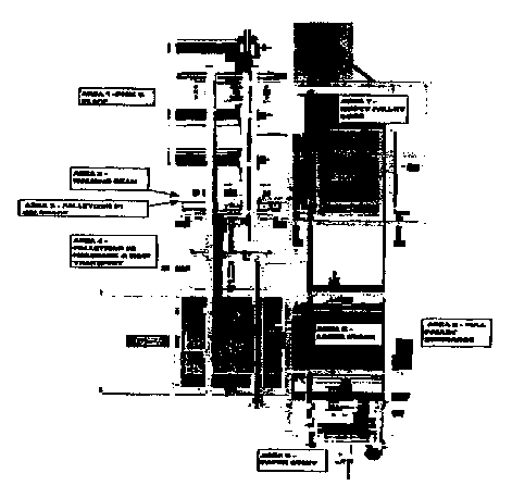
Figure 1 is a schematic plan view of the major components of
the system;
Figure 2 is an enlarged schematic plan view of the
palletizer and its components;
Figure 3 is a perspective view of the Pick and Place
mechanism in the palletizer;
Figure 4 is a perspective view of the walking beam
mechanism;
Figure 5 is a perspective view of the first palletizer hold
back device;
Figure 6 is a pictorial view of the stick crowder device;
Figure 7 is a pictorial view of the second palletizer hold
back and row transport mechanism;
Figure 8 is a perspective view of the row offset control
cylinder;
Figure 9 is a perspective view of the main table in the
palletizer;
Figure 10 is a perspective view of the empty pallet storage
lift;
Figure 11 a perspective view of the empty pallet shuttle;
Figure 12 is a pictorial view of the full pallet lift;
Figure 13 is a perspective view of the row cutoff and row
tamp devices;
Figure 14 is a perspective view of the row supports;
Figure 15 is a perspective view of the snake wrap carriage,
including the paper stuffer and cardboard lift vacuum cup;
Figure 16 is a perspective view showing the snake wrap paper
cutter;
Figure 17 is a pictorial view of the full pallet lift and
pallet discharge roller table;
CA 02305664 2000-03-28
WO 99/16672 PCTIUS98/20409
5-
Figure 18 is a pictorial view of the partial pallet restart
alignment arm:
Figure 19 is a pictorial view of the manual stick insert
tray;
Figure 20 is a side view of the thread up schematic for the
snake wrap:
Figure 21 is a perspective view of the snake wrap carriage,
viewed from ground level; and
Figures 22A & 22B are together the Process Flow Chart for
the palletizes operation.
Description of the Preferred Embodiment
Best Mode for Carrying Out the Invention
The present invention is directed to an improved palletizes
apparatus which is part of a bagger/palletizer system.
To understand the following description, it is desirable to
include first definitions of certain terms, as follows:
A "Stick" is a bag filled with a predetermined number of can
ends or lids:
A "Skid" refers to the wooden structure on which a pallet of
sticks is built; Filled pallets are formed in the
palletizes apparatus:
"Bagger" refers to the portion of the system that forms the
sticks by counting ends from the lead (foremost) end in a
stream of can ends which are supplied to the bagger
apparatus along in-feed rails, the ends being placed on edge
and moving face-to-face along such rails; The bagger counts
a predetermined number of ends, separates them from the
following stream, and places them into a bag, then folds and
seals the bag; Sticks are formed in the bagger apparatus, as
disclosed in the related International Application PCT/US98/
(Docket DSG 006 P2);.
"Palletizes" refers to the portion of the system that builds
layers of filled, sealed bags and places them onto a skid.
The Palletizes
CA 02305664 2000-03-28
WO 99/16672 PCT/US98/20409
6-
The Pick and Place, seen in Fig. 3, removes the filled,
sealed bags from the stick discharge grippers of the bagger
folding mechanism, and places them on the walking beam mechanism
WB (Fig. 4). The walking beam mechanism in turn places each of
the sticks in the appropriate position in the staging area. The
first (or temporary) hold back device PH-1(Fig. 5), is comprised
of three fingers PH-11 which can inhibit the first stick from
rolling, and retain the row until the Primary Hold back is
reached.
As each stick is placed, the Stick Crowder, also seen in
Fig. 6, forces the factory sealed or closed end (against which
the ends are pushed in the stick formation) of the bag against a
stainless steel place to ensure that each row of the pallet is
properly packed.
The Primary Hold back retains the row during building while
sticks 8-16 are placed. In conjunction with the Pull Off, the
Primary Hold back transfers the completed layer to the Main
Table.
Fig. shows the Pull Off, which clamps the row against the
Primary Hold back, and transfers the completed layer of the
pallet from the staging area to the Main Table.
The Main Table is a movable platform that extends over the
pallet and places a completed layer of sticks.
The Skid Storage Lift is the loading point for the empty
skids. The X and Y Skid Positioners locate the top skid against
the Skid Back Stop.
Figure 11 shows the Skid Shuttle, which contains the Skid
trippers that clamp and align the top skid and transport it to
the Pallet Zift area.
The Pallet Zift is the hydraulic lift on which the skid is
filled with completed layers. The Pallet Zift has a motorized
roller table to transport the finished pallet to the Pallet
Discharge Roller Table for removal by the operator.
CA 02305664 2000-03-28
WO 99/16672 PCTIUS98/20409
7_
The Row Cut Off, shown in Fig. 13, inhibits the row of
sticks from retracting with the Main Table.
The Front and Rear Vertical Tampers, also shown in Figure
2.22, compact the pallet as each new layer is placed.
The Upper Side Guides impose the row offset and retain the
layer of sticks as it is placed on the pallet. The Zower Side
Guides restrain the palliated layer, and support and compact the
new layer being placed.
1. The Snake Wrap Carriage, seen in Figure 20, covers
20 each completed layer with paper after the layer is transferred to
the Pallet Zift.
2. The Paper Stuffer (Area 6, Fig. 2) tucks the first
layer of paper underneath the cardboard on the skid.
3. The Snake Wrap Paper Cutter cuts the wrap at the
completion of the pallet.
The Pallet Discharge Roller Table, shown in Figure 17 is a
motorized roller table that moves the completed pallet away from
the pallet building area for removal by the operator. This
section describes the procedures required to prepare the system
for operation. It is divided into two sections; Palletizer and
Bagger.
Fig. 20 is a schematic of the Snake Wrap Carriage that shows
the proper thread up of the Snake Wrap Roll from the Snake Wrap
Catwalk vantage point. Fig. 21 is a pictorial view from the same
vantage point.
To load the Snake Wrap roll from the catwalk during system
set-up, referring to Fig. 20:
1. Open the Snake Wrap Catwalk door guard.
2. Remove the Split Collar from the Paper Roll
Cylinder.
3. Align the Paper Roll such that the paper feeds
counterclockwise from the top of the roll.
4. Slide the properly aligned Paper Roll onto the
Paper Roll Cylinder.
CA 02305664 2000-03-28
WO 99/16672 PCT/US98/20409
8_
5. Replace the Collar.
6. Thread the paper into the pinch rolls ensuring that
the paper feeds underneath the tensioning rod prior to the pinch
rolls.
7. Feed the paper between the stainless steel paper
guide and the roller guide.
8. Feed the paper between the spring loaded Paper
Clamp and the Roller Guide.
9. Thread the paper through the Slot below the Roller
Guide.
[Close all door guards.]
The manually feed the paper by depressing and holding the
Snake Wrap Jog push button, being sure to feed a sufficient
amount of paper to ensure the Snake Wrap is dispensing properly.
The snake wrap paper is cut with a double-edge, carpet knife
blade.
The skid storage lift (Fig. 10) can hold up to 10 empty
skids. To load the skids onto the skid storage lift, open the
door guard and place the stack of skids onto the left. Then push
the stack against the stops at the rearmost and right most
positions, and close the door guard.
Prior to homing the Palletizes, it is necessary to ensure
that the Skid Storage Lift and Pallet Zift are in the lowest
position. It is also necessary to remove all sticks from the
Pick & Place, the temporary staging area, and the Main Table, and
to remove any partial pallets or empty skids from the pallet
lift .
Operating Sequence
The pick and place mechanism PP(Fig. 3) removes a stick from
the stick discharge of the Bagger apparatus, and places it on the
walking beam WB (Fig. 4). Then the walking beam WB places the
first stick against the temporary hold back HB-1 (Fig. 5). Those
steps are repeated until a complete layer (sixteen sticks) is
built. During the building process, the temporary hold back HB-1
CA 02305664 2000-03-28
WO 99/16672 PCTIUS98/20409
9_
and previously placed sticks are pushed progressively farther
from walking beam WB as each of the sticks 1--7 are placed.
After the 7th stick is placed, the temporary hold back HB-1
rotates below the level of the sticks, returns to its home
position, and the primary hold back HB-2 begins retaining the
layer. The primary hold back HB-1 and previously placed sticks
continue to be pushed away from the walking beam WB as sticks
8--16 are placed (see Fig. 7).
The row transport RT lowers into position and clamps the
completed layer against the primary hold back HB-2. The row
transport RT and hold back HB-2 transport the completed layer
from the layer building area to the main table MT. The offset
cylinder OC (Fig. 8) extends and stops the row transport RT at
the appropriate location for the row offset. The main table
retainers MTR (Fig. 9) clamp the positioned layer. Then, the row
transport RT and hold back HB-2 return to their home position.
Next, the main table MT extends out over the pallet (Fig. 2)
and the row cut off RCO lowers. The main table MT then retracts
while the row cut off RCO hold the layer of sticks in place.
Effectively they are wiped off the main table onto the top of the
load on the pallet. The row supports RS (Fig. 14) restrain the
layer after it is positioned, and the row tamp RT (Fig. 13)
compacts the layers on the pallet as each layer is placed.
The snake wrap carriage SWC drapes a layer of wrap on top of
the completed layer, and waits on the opposite side of the pallet
for the next layer to be placed. The row tamp again compacts the
layers of the pallet. The foregoing steps are repeated until the
pallet is complete, normally when 27 rows are in place.
After completing the last layer of paper wrap, the snake
wrap paper cutter WPC cuts the wrap from the roll. The full
pallet lift FPZ then lowers to its discharge position. The
motorized roller table on the full pallet lift turns on and
transports the full pallet to the pallet discharge roller table
DRT. It in turn transports the pallet away from the pallet
CA 02305664 2000-03-28
WO 99/16672 PCT/US98/20409
10-
building area to allow the operator to remove the completed
pallet. The empty pallet shuttle EPS transports an empty pallet
from the empty pallet storage lift to the pallet Zift PL to begin
building the next pallet.
While the methods and apparatus for carrying these methods
into effect, constitute preferred embodiments of this invention,
it is to be understood that the invention is not limited to these
precise methods and forms of apparatus, and that changes may be
made in either without departing from the scope of the invention,
which is defined in the appended claims.