Language selection

Search

Patent 2305924 Summary

Third-party information liability

Some of the information on this Web page has been provided by external sources. The Government of Canada is not responsible for the accuracy, reliability or currency of the information supplied by external sources. Users wishing to rely upon this information should consult directly with the source of the information. Content provided by external sources is not subject to official languages, privacy and accessibility requirements.

Claims and Abstract availability

Any discrepancies in the text and image of the Claims and Abstract are due to differing posting times. Text of the Claims and Abstract are posted:

  • At the time the application is open to public inspection;
  • At the time of issue of the patent (grant).
(12) Patent: (11) CA 2305924
(54) English Title: SNOWMOBILE TRACK BELT
(54) French Title: CHENILLE DE MOTONEIGE
Status: Term Expired - Post Grant Beyond Limit
Bibliographic Data
Abstracts

English Abstract

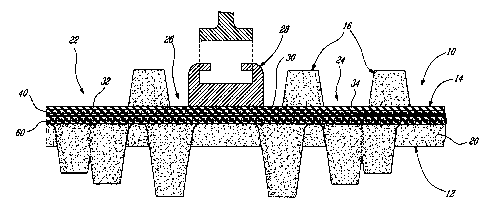
The invention relates to an improvement in a snowmobile endless track belt of the type comprising a body made of an elastomeric material, an outer surface for contact with the ground and an inner surface provided with lugs for engagement with the snowmobile driving system and with at least one endless pathway that contacts a corresponding slide rail of the snowmobile suspension. The improvement is characterized in that the elastomeric material, in at least the area which is contacted by the slide rail, is composed of rubber and of a lubricating material so that friction generated between the slide rail and a driven belt is greatly reduced by the presence of such lubricating material in the elastomeric material.


French Abstract

L'invention concerne une amélioration dans une courroie de chenille sans fin de motoneige du type comprenant un corps fait d'un matériau élastomère, une surface externe pour un contact avec le sol et une surface interne munie d'ergots pour une mise en prise avec le système d'entraînement de la motoneige et avec au moins une voie sans fin qui est en contact avec un rail à glissière correspondant de la suspension de motoneige. L'amélioration est caractérisée en ce que le matériau élastomère, dans au moins la zone qui est en contact avec le rail à glissière, est composé de caoutchouc et d'un matériau lubrifiant de sorte que le frottement généré entre le rail à glissière et une courroie entraînée soit considérablement réduit par la présence de ce matériau lubrifiant dans le matériau élastomère.

Claims

Note: Claims are shown in the official language in which they were submitted.


CLAIMS
1. In an endless track belt for vehicles moving mainly on snow
surfaces, said track belt comprising a body made of an elastomeric material;
said
body having an outer surface for contact with the snow surface and an inner
surface provided with means for engagement with driving means and at least one
endless pathway having a sliding surface contacting a corresponding slide rail
of
a vehicle rail suspension; said elastomeric material being formed, in at least
the
area contacted by the slide rail, of a layer of a composition of rubber and a
lubricating material so that friction between the slide rail and the endless
driving
track, when driven, is reduced due to the presence of said lubrication
material
migrating at said sliding surface.
2. An endless track belt according to claim 1, wherein said
composition layer of rubber and lubrication material is provided in only those
areas of the track belt that come in contact with the slide rails.
3. An endless track belt as defined in claim 1, wherein the entire
inner surface of the track belt is formed of said composition layer of rubber
and
lubrication material.
4. A method of making a molded track for use with a snowmobile
having a suspension system equipped with slide rails comprising:
preparing a mold press consisting of a stationary inner mold and
a movable outer mold;
laying a first layer of a composition of rubber and lubrication
material on said inner mold;
laying layers of rubber and fabrics adjacent to and/or on said first
layer; and
vulcanizing said first layer and said layers of rubber and fabrics to
form a molded track whereby said first layer defines at least an endless
sliding
pathway of the track to come in contact with the slide rails of the slide rail
suspension.

5. A method of making a molded track for use with a snowmobile
comprising:
placing first layers of a composition of rubber and lubrication
material on a stationary inner mold;
placing first layers of rubber and fabrics on said inner mold in
areas other than taken by said first composition layers;
placing a series of reinforcing rods transversely of said first layers
of rubber and fabrics and said first layers of composition of rubber and
lubrication
material at predetermined longitudinal spacings along said inner mold;
placing additional layers of rubber and fabrics over all said first
layers and over said rods;
pressing a movable outer mold onto said assembly; and
vulcanizing said rubber to form a molded track having, on an inner
surface thereof, endless pathways of rubber and lubrication material to
provide
frictionless sliding surfaces between said slide rails and said track.


Description

Note: Descriptions are shown in the official language in which they were submitted.


CA 02305924 2000-04-13
-1-
TITLE OF THE INVENTION
Snowmobile track belt.
FIELD OF THE INVENTION
The present invention relates to a belt for a track-driven vehicle, such as a
snowmobile.
DESCRIPTION OF THE PRIOR ART
Track belts provided on motor driven vehicles, such as snowmobiles, usually
comprise a body made of elastomeric material. This body has an outer
surface which contacts the ground and an inner surface which cooperates
with a slide suspension system and a driving system. Generally, the body
is driven by one of several driving wheels, such as sprocket wheels, which
engage openings or driving lugs provided on the inner surface of the track
belt. The slide suspension system is designed for supporting the chassis of
the vehicle and usually comprises a pair of parallel slide rails contacting
the
inner surFace of the track belt. Such rails also support the track belt with
respect to lateral movements.
Formerly, each slide rail of a slide suspension system was aligned with a
corresponding row of openings designed for engagement with teeth of a
corresponding sprocket wheel. Such positioning of the slide rails reduces
the portion of the inner surface of the track belt that is in contact with the
slide rails and thus the amount of friction therebetween. It was found that,
eventhough the friction was reduced, failures and rapid wear of the track belt
and slide rails were still observed. To overcome this drawback, in US
Patent No. 3,887,243 (Chaumont), the portions of the inner surface
contacting the slide rails were provided with metal clips to reduce friction
occurring between the inner surface of the body and the slide rails. It is
also

CA 02305924 2000-04-13
_2_
well known in the prior art that, in order to minimize friction between the
inner
surface of the track belt and the slide rails and also to facilitate the
positioning of the clips, the slide rails were positioned above a
corresponding pathway of clips essentially separated from each other by a
hole.
It is also known in the art that, to maintain a sufficient sturdiness of the
track
belt, it is advantageous to have a maximum amount of clips. However, this
increases the weight of the track belt. Therefore, there is a strong need for
a track belt that does not have the drawback of those of the prior art with
respect to friction existing between the inner surface of the track belt and
the
slide rails while reducing the whole weight of the track belt.
Therefore, the prior art teaches to the man skilled in the art that slide
rails
must contact a maximum of frictionless clips and a minimum of the inner
surface of the track belt.
OBJECTS AND STATEMENT OF THE INVENTION
An object of the invention is to embody a track belt for motor vehicles, such
as snowmobiles, having to cooperate with slide rails of a slide suspension
system, which shows at once high characteristics of strength, resistance and
durability, avoids friction between its inner surface and the slide rails and
hay
a reduced weight with respect to track belts already known in the art.
Another object of the present invention is to enable the formation of a
lubricating effect between the slide rails and the inner surface of the track
belt in order to achieve this friction reduction.

CA 02305924 2002-12-13
-3-
Another object of the invention concerns a method for making a snowmobile
track with a view to minimizing friction between the slide rails and the
corresponding inner surface of the track belt.
However, contrary to the teachings of the prior art, the applicant has
surprisingly found that it is possible to have a substantial portion of the
inner
surface in contact with slide rails, while still limiting the friction
existing
between them. More particularly, the applicant has dliscovered an
improvement in an endless track belt of the type comprising a body made of
an elastomeric material, the body having an outer surface for contact with the
ground and an inner surface provided with means for engagement with
4 ~ driving means. The inner surface is also provided with at lea:>t one
endless
pathway having a sliding surface contacting a corresponding slide rail of a
slide rail suspension. The elastomeric material of the track belt is composed
of rubber and a lubrication means so that, at the sliding contaict of the
inner
surface of the track belt,~..f~ictio~n is greatly reduced due to the presence
of
such lubrication migrating to this inner surface of the track.
In one preferred form of the invention, this composition of rubber material
and lubricating means is provided only in the endless pathway of the track
which contacts the slide rail of the sliding rail suspension.
In another form of the invention, the complete inner surface of the track belt
is composed of a layer of rubber and lubricating means.
Other objects and further scope of applicability of the present invention will
become apparent from the detailed description given hereinafter. It should
be understood, however, that this detailed description, while indicating
preferred embodiments of the invention, is given by way of illustration only,
since various changes and modifications within the spirit arnd scope of the
invention will become apparent to those skilled in the art.

CA 02305924 2000-04-13
-4-
BRIEF DESCRIPTION OF THE DRAWINGS
Figure 1 is a cross-sectional view of one embodiment of a track belt made
in accordance with the present invention; and
Figure 2 is a cross-sectional view of another embodiment of a track belt
made in accordance with the present invention.
DESCRIPTION OF PREFERRED EMBODIMENTS
Referring to figure 1, there is shown a cross-sectional view of part of a
snowmobile track belt 10 comprising an outer surface 12 and an inner
surface 14, the latter being provided with integrally formed lugs 16 which are
drivingly engageable by driven sprockets (not shown) on the snowmobile.
The track is made of rubber as its main component; but, in most cases it
includes a plurality of layers of reinforcing woven fabric. The track is also
reinforced by means of a plurality of rods extending transversely of the track
and embedded in the rubber material in areas such as 20. In most cases,
the trade consists of a pair of opposite lateral sections, one being shown as
22, and an intermediate central portion 24, the three sections being
separated from one another by means of a part of pathways, one being
shown as 26, which may include a series of longitudinally spaced openings;
however, these openings can be completely filled. This pathway 26, on the
inner surface 14 of the track belt, serves to receive the lower face of a
slide
rail 28 which forms part of the suspension system of the snowmobile (in most
cases, there are two slide rails per suspension). In those snowmobile tracks
that do not have lugs 16, the driving of the track is achieved by means of
sprockets having peripheral lugs that are received in a series of
longitudinally
spaced openings provided in the pathway 26.

CA 02305924 2002-12-13
-5-
The slide rail 28 is preferably made of low friction material. This material
is
usually a plastic material, such as ultra high molecular weighs: polyethylene.
Structural details by which the slide rails are mechanically fastened to the
remain of the suspension system have been voluntarily omitted for
clarification purposes. Those characteristics are of course well known in the
art and do not need any extensive description..
The conventional way of making a snowmobile track is to place a layer of
rubber and woven fabrics on the inner mold of a press, placing a series of
transverse rods at peripheral intervals over this first layer, laying
additional
layers of rubber and woven fabrics thereover, closing an ouier mold of the
,_.,
..:' press over these layers, and then vulcanising the rubber so that the
track is
molded with the rods embedded in the rubber and fabrics body. Once the
rubber is cured, the outer mold is distanced radially from the sinner mold,
the
track is removed from the inner mold and, in cases where i:he track to be
formed is provided with a series of sprocket engaging holes, it is brought to
another station where these holes are punched out of the track. Then,
metallic clips are positioned adjacent these holes to provide this sliding
contact existing in prior art tracks as explained above.
The present invention is concerned with reducing the friction that exists
between the slide rail 28 and the inner surface 30 of the track when driven
at high speed.
In the case of the track illustrated in figure 1, the~cross section of the
layer
of material at track section 26 is represented as being different from that of
the remaining track sections 32 and 34. At 30 the layer of elastomeric
material consists of a composition of rubber and of a lubrication means. One
example of such composition which has never been used in tlhe snowmobile
industry is the one sold on the market by Ad~ranced Rubber Compounding
Limited under series number 5482-s or 54.83.

CA 02305924 2000-04-13
-6-
In making the snowmobile track illustrated in figure 1, a mold press
consisting of a stationary inner mold and a movable outer mold is prepared.
Then, a layer in the form of band consisting of the composition of rubber and
lubricating means in accordance with the present invention is placed at a
given area on the mold; for track suspension using two slide rails, two layers
30 are laterally placed on the inner mold at these areas such as 26. Then,
layers 32 and 34 of rubber and woven fabrics are laid in the remaining areas
22 and 24. A series of reinforcing rods are laid over the layers 30, 32 and 34
and then additional layers of fabrics and rubber 40 and 60 are placed
thereover. Then, the outer mold of the press which consists of a series of
peripheral segments is radially moved towards the inner mold with the layers
thereon. The construction of such mold press is well known in the art and
wilt not be described in detail; they include means for vulcanizing the rubber
material once the radially moved segments are moved in contact with the
track components on the inner mold. The vulcanizing process results in the
making of an integral body of all the components. Once cured, the outer
mold is retracked and the formed track is removed.
Referring to figure 2, a second embodiment 10' of a track made in
accordance with the present invention is shown again partly in cross section.
The only difference existing between the embodiments of figure 1 and figure
2 is that the inner surface 14' extends the entire width of the track; hence,
it
is not, as is the case in track 10 of figure 1, present only in those areas
which
are to be contacted by the slide rails 20'. All the components of the track
10'
shown in figure 2 bear the same reference numerals as in the figure 1 with
the exception of a prime mark and with the further exception that the inner
surface 14' has a layer 70 with a width corresponding substantially to the
width of the inner mold of the press, (and consequently of the track):
Therefore, once this layer of rubber and lubricating means is placed on the
inner mold, the other steps involved in the making of the snowmobile track

CA 02305924 2000-04-13
_7_
are the same as that described above with respect to the embodiment
illustrated in figure 1.
Although the invention has been described above with respect to two specific
embodiments, it will be evident to a person skilled in the art that it may be
modified and refined in various ways. It is therefore wished to have it
understood that the present invention should not be limited in scope, except
by the terms of the following claims.

Representative Drawing
A single figure which represents the drawing illustrating the invention.
Administrative Status

2024-08-01:As part of the Next Generation Patents (NGP) transition, the Canadian Patents Database (CPD) now contains a more detailed Event History, which replicates the Event Log of our new back-office solution.

Please note that "Inactive:" events refers to events no longer in use in our new back-office solution.

For a clearer understanding of the status of the application/patent presented on this page, the site Disclaimer , as well as the definitions for Patent , Event History , Maintenance Fee  and Payment History  should be consulted.

Event History

Description Date
Inactive: COVID 19 - Reset Expiry Date of Patent to Original Date 2020-06-16
Inactive: COVID 19 - Deadline extended 2020-06-10
Inactive: COVID 19 - Deadline extended 2020-05-28
Inactive: COVID 19 - Deadline extended 2020-05-14
Inactive: COVID 19 - Deadline extended 2020-04-28
Inactive: Expired (new Act pat) 2020-04-13
Inactive: COVID 19 - Deadline extended 2020-03-29
Common Representative Appointed 2019-10-30
Letter Sent 2019-04-15
Maintenance Request Received 2018-04-13
Maintenance Request Received 2017-04-05
Maintenance Request Received 2015-03-16
Change of Address or Method of Correspondence Request Received 2015-03-04
Letter Sent 2013-09-03
Inactive: Correspondence - Transfer 2013-06-21
Letter Sent 2011-08-05
Letter Sent 2011-02-23
Revocation of Agent Requirements Determined Compliant 2008-08-28
Appointment of Agent Requirements Determined Compliant 2008-08-28
Inactive: Office letter 2008-08-27
Revocation of Agent Request 2008-08-15
Appointment of Agent Request 2008-08-15
Appointment of Agent Request 2008-06-16
Revocation of Agent Request 2008-06-16
Grant by Issuance 2003-12-30
Inactive: Cover page published 2003-12-29
Inactive: Final fee received 2003-10-16
Pre-grant 2003-10-16
Notice of Allowance is Issued 2003-04-30
Letter Sent 2003-04-30
Notice of Allowance is Issued 2003-04-30
Inactive: Approved for allowance (AFA) 2003-04-22
Amendment Received - Voluntary Amendment 2003-03-11
Inactive: S.30(2) Rules - Examiner requisition 2003-02-13
Amendment Received - Voluntary Amendment 2002-12-13
Inactive: S.30(2) Rules - Examiner requisition 2002-06-28
Amendment Received - Voluntary Amendment 2002-05-14
Inactive: S.30(2) Rules - Examiner requisition 2001-11-16
Application Published (Open to Public Inspection) 2001-10-13
Inactive: Cover page published 2001-10-12
Advanced Examination Determined Compliant - paragraph 84(1)(a) of the Patent Rules 2001-09-13
Letter sent 2001-09-13
Letter Sent 2001-09-10
Inactive: Advanced examination (SO) 2001-08-30
Request for Examination Requirements Determined Compliant 2001-08-30
Inactive: Advanced examination (SO) fee processed 2001-08-30
All Requirements for Examination Determined Compliant 2001-08-30
Request for Examination Received 2001-08-30
Letter Sent 2000-08-03
Inactive: First IPC assigned 2000-06-29
Inactive: IPC assigned 2000-06-28
Inactive: Single transfer 2000-06-20
Inactive: Courtesy letter - Evidence 2000-06-06
Inactive: Filing certificate - No RFE (English) 2000-05-31
Application Received - Regular National 2000-05-26

Abandonment History

There is no abandonment history.

Maintenance Fee

The last payment was received on 2003-02-18

Note : If the full payment has not been received on or before the date indicated, a further fee may be required which may be one of the following

  • the reinstatement fee;
  • the late payment fee; or
  • additional fee to reverse deemed expiry.

Patent fees are adjusted on the 1st of January every year. The amounts above are the current amounts if received by December 31 of the current year.
Please refer to the CIPO Patent Fees web page to see all current fee amounts.

Owners on Record

Note: Records showing the ownership history in alphabetical order.

Current Owners on Record
CAMOPLAST SOLIDEAL INC.
Past Owners on Record
DENIS COURTEMANCHE
Past Owners that do not appear in the "Owners on Record" listing will appear in other documentation within the application.
Documents

To view selected files, please enter reCAPTCHA code :


To view images, click a link in the Document Description column. To download the documents, select one or more checkboxes in the first column and then click the "Download Selected in PDF format (Zip Archive)" or the "Download Selected as Single PDF" button.

List of published and non-published patent-specific documents on the CPD .

If you have any difficulty accessing content, you can call the Client Service Centre at 1-866-997-1936 or send them an e-mail at CIPO Client Service Centre.


Document
Description 
Date
(yyyy-mm-dd) 
Number of pages   Size of Image (KB) 
Representative drawing 2001-09-16 1 25
Description 2002-12-12 7 309
Claims 2002-12-12 2 71
Claims 2003-03-10 2 66
Abstract 2000-04-12 1 21
Claims 2000-04-12 2 69
Description 2000-04-12 7 298
Drawings 2000-04-12 2 80
Courtesy - Certificate of registration (related document(s)) 2000-08-02 1 115
Filing Certificate (English) 2000-05-30 1 164
Acknowledgement of Request for Examination 2001-09-09 1 194
Reminder of maintenance fee due 2001-12-16 1 112
Commissioner's Notice - Application Found Allowable 2003-04-29 1 160
Maintenance Fee Notice 2019-05-26 1 182
Maintenance Fee Notice 2019-05-26 1 181
Fees 2003-02-17 1 37
Correspondence 2003-10-15 1 29
Fees 2002-03-04 1 39
Fees 2004-03-09 1 33
Fees 2005-02-22 1 33
Fees 2006-02-19 1 41
Fees 2007-03-26 1 43
Correspondence 2008-06-15 3 38
Fees 2008-03-17 1 45
Correspondence 2008-08-14 3 69
Correspondence 2008-08-26 1 16
Correspondence 2008-08-26 1 23
Fees 2015-03-15 2 79
Correspondence 2015-03-03 3 123
Maintenance fee payment 2017-04-04 2 80
Maintenance fee payment 2018-04-12 1 61
Filing Certificate (English) 2000-05-30 1 22
Returned mail 2019-06-12 2 89