Note: Descriptions are shown in the official language in which they were submitted.
CA 02306030 2000-03-29
WO 99/17094 PCT/US98120340
CONSUMABLE FOR LASER CAPTURE MICRODISSECTION
BACKGROUND OF THE INVENTION
1. Field of the Invention
The present invention relates generally to the field of laser capture
microdissection (LCM). More particularly, the present invention relates to
apparatus for acquiring LCM samples that include an LCM film mounted on at
least a part of the interior of an analysis container. Specifically, a
preferred
implementation of the present invention relates to a substantially planarized
ethylene vinyl acetate (EVA) polymer LCM film that is hot vacuum baked onto
the bottom of a microcentrifuge tube cap. The present invention thus relates
to
an LCM sample acquisition apparatus of the type that can be termed planar cap.
2. Discussion of the Related Art
Diseases such as cancer have long been identified by examining tissue
biopsies to identify unusual cells. The problem has been that there has been
no
satisfactory prior-art method to extract the cells of interest from the
surrounding
tissue. Currently, investigators must attempt to manually extract, or
microdissect, cells of interest either by attempting to mechanically isolate
them
with a manual tool or through a convoluted process of isolating and culturing
the
cells. Most investigators consider both approaches to be tedious, time-
consuming, and inefficient.
A new technique has been developed which can extract a small cluster of
cells from a tissue sample in a matter of seconds. The technique is called
laser
capture microdissection (LCM). Laser capture microdissection is a one-step
technique which integrates a standard laboratory microscope with a low-energy
laser and a transparent ethylene vinyl acetate polymer thermoplastic film such
as
is used for the plastic seal in food product packaging.
CA 02306030 2000-03-29
WO 99/17094 PCT/US98/20340
2
In laser capture microdissection, the operator looks through a
microscope at a tissue biopsy section mounted on a standard glass
histopathology slide, which typically contains groups of different types of
cells.
A thermoplastic film is placed over and in contact with the tissue biopsy
section.
Upon identifying a group of cells of interest within the tissue section, the
operator centers them in a target area of the microscope field and then
generates
a pulse from a laser such as a carbon dioxide laser having an intensity of
about
50 milliwatts (mVl~ and a pulse duration of between about 50 to about 500
milliseconds (mS). The laser pulse causes localized heating of the plastic
film as
it passes through it, imparting to it an adhesive property. The cells then
stick to
the localized adhesive area of the plastic tape directly above them, whereupon
the cells are immediately extracted and ready for analysis. Because of the
small
diameter of the laser beam, extremely small cell clusters may be
microdissected
from a tissue section.
By taking only these target cells directly from the tissue sample, scientists
can immediately analyze the gene and enzyme activity of the target cells using
other research tools. Such procedures as polymerise chain reaction
amplification of DNA and RNA, and enzyme recovery from the tissue sample
have been demonstrated. No limitations have been reported in the ability to
amplify DNA or RNA from tumor cells extracted with laser capture
microdissection.
Laser capture microdissection has successfully extracted cells in all
tissues in which it has been tested. These include kidney glomeruli, in situ
breast
carcinoma, atypical ductal hyperplasia of the breast, prostatic
interepithielial
neoplasia, and lymphoid follicles. The direct access to cells provided by
laser
capture microdissection will likely lead to a revolution in the understanding
of
the molecular basis of cancer and other diseases, helping to lay the
groundwork
for earlier and more precise disease detection.
Another likely role for the technique is in recording the patterns of gene
expression in various cell types, an emerging issue in medical research. For
CA 02306030 2002-06-05
WO 99/17094 PCT/US98/20340
3
instance, the National Cancer Institute's Cancer Genome Anatomy Project
(CGAP) is attempting to define the patterns of gene expression in normal, pre-
cancerous, and malignant cells. In projects such as CGAP, laser capture
microdissection is a valuable tool for procuring pure cell samples from tissue
samples.
The LCM technique is generally described in the recently published
article: Laser Capture Microdissection, cie , Volume 274, Number 5289,
Issue 8, pp 998-1001, published in 1996 . The purpose of the LCM
technique is to provide a simple method for the procurement
of selected human cells from a heterogeneous population
contained on a typical histopathology biopsy slide.
A typical tissue biopsy sample consists of a 5 to 10 micron slice of tissue
that is placed on a glass microscope slide using techniques well known in the
field of pathology. This tissue slice is a cross section of the body organ
that is
being studied. The tissue consists of a variety of different types of cells.
Often a
pathologist desires to remove only a small portion of the tissue for further
analysis.
LCM employs a thermoplastic transfer film that is placed on top of the
tissue sample. This film is manufactured containing organic dyes that are
chosen
to selectively absorb in the near infrared region of the spectrum overlapping
the
emission region of common AIGaAs laser diodes. When the film is exposed to
the focused laser beam the exposed region is heated by the laser and melts,
adhering to the tissue in the region that was exposed. The film is then lifted
from
the tissue and the selected portion of the tissue is removed with the film.
Thermoplastic transfer films such as a 100 micron thick ethyl vinyl
acetate (EVA) film available from Electroseal Corporation of Pompton Lakes,
New Jersey (type E540) have been used in LCM applications. The film is chosen
to have a low melting point of about 90°C.
The thermoplastic EVA films used in LCM techniques have been doped
with dyes, such as an infrared napthalocyanine dye, available from Aldrich
CA 02306030 2000-03-29
WO 99/17094 PCTIUS98/20340
4
Chemical Company (dye number 43296-2 or 39317-7). These dyes have a
strong absorption in the 800 nm region, a wavelength region that overlaps with
laser emitters used to selectively melt the film. The dye is mixed with the
melted
bulk plastic at an elevated temperature. The dyed plastic is then manufactured
into a film using standard film manufacturing techniques. The dye
concentration
in the plastic is about 0.001 M.
While the films employed in LCM applications have proved satisfactory
for the task, they have several drawbacks. The optical absorption of a dye
impregnated film is a function of its thickness. This property of the film may
be
in conflict with a desire to select film thickness for other reasons.
The organic dyes which are used to alter the absorption characteristics of
the films may have detrimental photochemistry effects in some cases. This
could
result in contamination of LCM samples, In addition, the organic dyes employed
to date are sensitive to the wavelength of the incident laser light and thus
the film
must be matched to the laser employed.
SUMMARY OF THE INVENTION
An object of the invention is to improve the speed of the laser capture
microdissection technique. Another object of the invention is to improve the
accuracy of the laser capture microdissection technique. Another object of the
invention is to improve the reproducibility of the laser capture
microdissection
technique. Yet another object of the invention is to reduce the amount of
contamination involved with the laser capture microdissection technique.
Therefore, there is a particular need for an LCM consumable that integrates an
LCM film into the interior of an analysis container. A planar cap includes a
substantially planarized ethylene vinyl acetate (EVA) polymer LCM film that is
hot vacuum baked onto the bottom of a microcentrifizge tube cap. The laser
capture microdissection caps can be shipped as-baked (i. e., packaged without
post-bake processing) to protect the laser capture microdissection transfer
film
and minimize contamination. The cap, and the configuration in which it is
CA 02306030 2000-03-29
WO 99/17094 PCT/US98/20340
shipped, provides the additional advantages of quick and easy utilization.
Thus, it
is rendered possible to simultaneously satisfy the requirements of speed,
accuracy and resistance to contamination, which, in the case of the prior art,
are
mutually contradicting and cannot be simultaneously satisfied.
5 A first aspect of the invention includes a laser capture microdissection
assembly comprising: a plate having a substantially planar top surface; and at
least one laser capture microdissection cap connected to said substantially
planar
top surface of said plate, wherein said at least one laser capture
microdissection
cap includes a transfer film carrier having a substrate surface; and a
substantially
planarized laser capture microdissection transfer film connected to said
substrate
surface of said transfer film carrier. A second aspect of the invention
includes a
laser capture nucrodissection apparatus, comprising: a transfer film carrier
having a substrate surface; and a laser capture microdissection transfer film
coupled to said substrate surface of said transfer film carrier, said laser
capture
microdissection transfer film including at least one integrally formed
structural
feature that protrudes and provides a controllable spacing between said laser
capture microdissection transfer film and a sample. A third aspect of the
invention includes an integral portion of a biological reaction vessel,
comprising:
a transfer film carrier having a substrate surface; and a laser capture
microdissection transfer film coupled to said substrate surface of said
transfer
film carrier. A fourth aspect of the invention includes a laser capture
microdissection assembly comprising: a plate having a top surface; and at
least
one laser capture microdissection cap coupled to said top surface of said
plate,
wherein each of said at least one laser capture microdissection cap includes a
transfer film carrier having a substrate surface; and a laser capture
microdissection transfer film coupled to said substrate surface of said
transfer
film carrier.
A fifth aspect of the invention includes a method of making the laser
capture microdissection assembly comprising: providing a plate having a
substantially planar top surface; providing at least one laser capture
CA 02306030 2000-03-29
WO 99117094 PCT/US98/20340
6
microdissection cap, said at least one laser capture microdissection cap
including
a transfer film carrier having a substrate surface; providing a laser capture
microdissection transfer film adjacent to said substrate surface of said
transfer
film Garner; and hot vacuum baking said at least one laser capture
microdissection cap and said plate so as to substantially planarize said laser
capture microdissection transfer film. A sixth aspect of the invention
includes a
method of making a laser capture microdissection consumable, comprising:
providing a transfer film Garner having a substrate surface; and forming a
laser
capture microdissection transfer film on said substrate surface, wherein
forming
includes hot vacuum baking said laser capture microdissection transfer film. A
seventh aspect of the invention includes a method of making an integral
portion
of a biological reaction vessel, comprising: providing a transfer film carrier
having a substrate surface; and fabricating a laser capture microdissection
transfer film on said substrate surface. An eight aspect of the invention
includes
a method of making a laser capture microdissection assembly, comprising:
providing a plate having a top surface; providing at least one laser capture
microdissection cap, said at least one laser capture microdissection cap
including
a transfer film Garner having a substrate surface; providing, for said at
least one
laser capture microdissection cap, a laser capture microdissection transfer
film
coupled to said substrate surface of said transfer film carrier; placing said
at least
one laser capture microdissection cap in contact with said plate; and hot
vacuum
baking both said at least one laser capture microdissection cap and said plate
so
as to produce said laser capture microdissection assembly.
A ninth aspect of the invention includes a method of imaging a sample
with a microscope, comprising: providing said microscope; locating a
scattering
media within a beam path defined by said microscope and within a few
millimeters of a sample; and imaging said sample through said scattering media
with said microscope. A tenth aspect of the invention includes a microscope,
comprising: a scattering media located within a beam path defined by said
microscope and within a few millimeters of a sample.
CA 02306030 2000-03-29
WO 99/17094 PCT/US98120340
7
These, and other, aspects of the present invention will be better
appreciated and understood when considered in conjunction with the following
description and the accompanying drawings. It should be understood, however,
that the following description, while indicating preferred embodiments of the
present invention and numerous specific details thereof, is given by way of
illustration and not of limitation. Many changes and modifications may be made
within the scope of the present invention without departing from the spirit
thereof, and the invention includes all such modifications.
BRIEF DESCRIPTION OF TI-lE DRAWINGS
A clear conception of the advantages and features constituting the
present invention, and of the components and operation of model systems
provided with the present invention, will become more readily apparent by
referring to the exemplary, and therefore nonlimiting, embodiments illustrated
in
1 S the drawings accompanying and forming a part of this specification,
wherein like
reference numerals (if they occur in more than one view) designate the same
elements. Consequently, the claims are to be given the broadest interpretation
that is consistent with the specification and the drawings. It should be noted
that
the features illustrated in the drawings are not necessarily drawn to scale.
Figs. 1 A-1 C illustrate three views of a laser capture microdissection
(LCM) sample plate, representing an embodiment of the present invention;
Figs. 2A-2C illustrate three views of the sample plate shown in FIGS.
1 A-1 C after coating with a release agent, representing an embodiment of the
present invention;
Figs. 3A-3D illustrate four views of a sample Garner, representing an
embodiment of the present invention;
Figs. 4A-4D illustrate four views of the sample Garner illustrated in
FIGS. 3A-3D after an LCM film is added, representing an embodiment of the
present invention;
CA 02306030 2002-06-05
WO 99!17094 PCTNS98120340
8
Figs. SA-SC illustrate three views of an assembly that includes four of the
sample carriers depicted in FIGS. 4A-4D and one of the plates depicted in
FIGS.
2A-2C, representing an embodiment of the present invention;
Figs. 6A-6C illustrate three views of a completed assembly after vacuum
hot cast molding, representing an embodiment of the present invention;
Figs. 7A-7B illustrate two sequential views of a laser capture
microdissection film with molded features, representing an embodiment of the
present invention;
Fig. 8 illustrates a bottom view of a laser capture microdissection film
with molded features, representing an embodiment of the present invention;
Fig. 9 illustrates a side view of a laser capture microdissection apparatus,
rxpresenting an embodiment of the invention;
Fig. 10 illustrates a side view of a microcentrifuge tube cap with a
negative draft, representing an embodiment of the invention; and
Figs. 1 lA-11D illustrates a several views of a biological reaction vessel,
representing an embodiment of the invention.
DESCRIPTION OF PREFERRED EMBODIIvviENTS
The present invention and the various features and advantageous details
thereof are explained more fully with reference to the nonlimiting embodiments
that are illustrated in the accompanying drawings and detailed in the
following
description. Descriptions of well known components and processing techniques
are omitted so as not to unnecessarily obscure the present invention in
detail.
CA 02306030 2002-06-05
WO 99/17094 PC1'JUS98/20340
9
Turning to Figs. lA-1C, a plate 100 is depicted. Plate 100 can be
fabricated from metal, glass, ceramic, or any other material suitable for the
subsequent processing steps described below. In a preferred embodiment, plate
100 is a glass microscope slide. It is important that the top surface 1 O 1 of
plate
100 be flat. Although the depicted embodiment shows a bare microscope slide,
the plate can be coated, or otherwise surface treated, in a preliminary
processing
step.
Turning now to Figs. 2A-2C, the plate 100 is depicted with a release
agent 210. The release agent 210 is applied to the top surface 101. It will be
noted that the top surface I01 is obscured by the release agent 210 in Figs.
2A-
2B but is clearly visible as an interface in Fig. 2C.
The release agent can be any suitable nonadhesive material such as, for
example, silicones, or TEFLON * (i.e. , polytetraflu~roethylene) .
P~lvanta~uslY.
the release coating can be a surfactant that increases the contact angle of
liquids
with which it comes in contact. It is important that the release agent 210
maintain and extend the flatness provided initially by the top surface 101. In
a
preferred embodiment, the release agent 210 can include a silicone containing
surfactant agent such as, for example, RAIN-X.
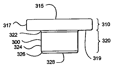
Turning now to Figs. 3A-3D, a sample carrier 300 is depicted. The
sample carrier 300 has an upper portion 3 I O and a lower portion 320. The
upper
portion 310 includes a top surface 315 and an outer perimeter 317, and a
shoulder 319. The lower portion 320 includes a flare 322, an inner perimeter
324, a taper 326 and a substrate surface 328.
The sample carrier 300 can be a polymeric cap that is of transparent
optical quality. For example, the cap could be fabricated from polycarbonate,
or
other suitable optically transparent plastic. However, the cap does not need
to
be optically transparent provided the absorption characteristics of the
polymer
from which it is made are compatible with suitable transmission of the laser
energy to the capture film.
* Trademark
CA 02306030 2000-03-29
WO 99/17094 PCT/US98120340
Turning now to Figs. 4A-4D, a laser capture microdissection (LCM)
transfer film 400 is shown being applied to the sample carrier 300. It will be
appreciated that the LCM transfer film 400 is depicted out of scale for the
sake
of clarity. The laser capture microdissection transfer film 400 can be applied
to
5 the bottom of a circular cap by punching a circular section from a free-
standing
sheet of ethylene vinyl acetate. Alternatively, the LCM transfer film 400 can
be
molded to the bottom of the cap. The LCM transfer film 400 can be deposited
on the cap using a process such as spin coating, dipping, or spraying. In any
event, manufacture of the consumable should be carried out in a sterile
10 environment.
It is advantageous that the LCM transfer film 400 be thin. For example,
a 50 micron thick film is preferable to a 100 micron thick film. However, the
film can advantageously be fabricated in thicknesses of approximately 500,
400,
300, 200, 100, 50 microns, or less.
Turning to Figs. SA-SC, a plurality of combined sample carriers 300
together with their corresponding LCM transfer films 400 are depicted being
lowered toward the release agent 210 that is coated on top of the plate 100.
The
LCM transfer films 400 can be an ethylene vinyl acetate (EVA} polymeric
material. It will appreciated that Fig. 5A depicts the assembly process at an
earlier point in time compared to Fig. SC wherein the gap between the LCM
transfer film 400 and the release agent 210 is almost closed.
Turning now to Figs. 6A-6C, the assembly of four sample carriers 300 on
plate 100 is depicted during the process step of vacuum hot baking. The
process
of vacuum hot baking causes the EVA to soften, melt and flow thereby
conforming to the substantially planar surface presented by the release agent
210. In this way, the flatness possessed by the plate 100 is transferred to
the
LCM transfer film 400. This also eliminates trapped air.
The hot vacuum baking of the film can take place in moderate vacuum.
In a preferred embodiment, the hot cast molding takes place at one torr and 95
degrees C for approximately one hour.
CA 02306030 2000-03-29
WO 99117094 PCT/US98I20340
11
In an alternative embodiment, instead of attaching the LCM film to the
base of the cap prior to its placement on top of the release agent coated
plate,
the LCM film can be coated on top of the release agent as a film layer. A
sample
carrier can then be placed on top of the LCM film. An assembly of one, or
more, such combinations can then be subjected to hot vacuum melt casting to
planarize at least that portion of the LCM film that is located at the
interface
between the sample carrier and the release agent. In this way, when the sample
carrier is removed from the plate, a portion of the planarized LCM film that
corresponds with the bottom surface of the sample Garner will be broken away
from the assembly together with the cap that is being removed. Those portions
of the LCM film that are not adjacent the bottom of the cap being removed will
remain on the plate. In a preferred embodiment; when the sample carrier is
pulled away from the plate, a twisting motion is applied to. the sample
carrier
either before and/or during linear separation of the two prime components so
as
to exert a sheer force both within the LCM film and between the LCM film and
the release layer.
The release coating can be a silicone. Alternatively, the release coating
can be a polytetrafluoroethylene.
Throughout this specification, the more descriptive phrase "transfer film
Garner" can be substituted for the phrase "sample carrier." In general, the
transfer film carrier carries the transfer film. Only that portion of the
sample that
is transferred to the transfer film is carried by the carrier.
The ethylene vinyl acetate can be selected from among the available
materials based on the following criteria. The ethylene vinyl acetate should
have
a high melt index. A high melt index is indicated by low viscosity and low
molecular weight.
It is important that the ethylene vinyl acetate, or other material being
used for the LCM transfer film, have a modest tack. Thus, the transfer film is
somewhat sticky but will not bind to everything with which it comes in
contact.
CA 02306030 2000-03-29
WO 99117094 PCT/US98/20340
12
The caps can be made from clear plexiglass G (i.e., polymethyl
methacrylate). By treating the glass slide with a surfactant before the caps
are
vacuum hot cast in place, the completed caps can be popped off the glass slide
just before they are needed for acquisition of sample material.
In a preferred embodiment, the cap is sized to fit in a standard
microcentrifuge tube. The LCM transfer film can be attached to the cap using
glue, or by welding the thermoplastic, or by some other mechanical means,
holding the film in place.
The side walls of the cap can have a negative draft. This negative draft
can be machined into the tooling with which the caps are made.
After capturing the tissue to be analyzed on the bottom of the cap, the
cap is placed on the microcentrifuge tube containing proteinase (i.e.,
protease,
e.g., Trypsin) solution and the tube is inverted. The tissue is then dissolved
and
the DNA is free to enter the solution. The solution is then pipetted out of
the
tube and into the PCR mixture.
While not being bound by theory, it is believed that the EVA film
expands both up and down when it is exposed to the energy from the laser. As
an approximation, it is believed that the EVA film expands approximately 12-
15% downward and upward when it is exposed to the LCM charge from the
laser. The upward expansion is restricted by the plastic cap.
The thickness of the LCM transfer film should be held to within 20%,
preferably S%. The bottom, exposed surface of the LCM transfer film can be
termed a capture surface. The flatness of the LCM transfer film should be held
to within approximately five microns, preferably approximately one micron. The
flatness of the film can readily characterized based on the number of fringes
multiplied by ~./2. The flatness of the LCM transfer film should preferably be
held to within two waves which is approximately equal to 1/4 micron per
fringe,
given a ~, of 540nm.
CA 02306030 2000-03-29
WO 99117094 PCT/tJS98/20340
13
The dye in the ethylene vinyl acetate is what absorbs the laser energy.
The ethylene vinyl acetate transforms to a liquid phase, infuses into the cell
structure of interest and then hardens.
The particular manufacturing process used for fabricating the assembly
should be inexpensive and reproducible. Conveniently, the fabrication of the
present invention can be carried out by using any coating and baking method.
It
is preferred that the process be conducted in a contaminant-free environment.
For the manufacturing operation, it is moreover an advantage to employ an
automated method.
However, the particular manufacturing process used for fabricating the
assembly is not essential to the present invention as long as it provides the
described assembly. Normally those who make or use the invention will select
the manufacturing process based upon tooling and energy requirements, the
expected application requirements of the final product, and the demands of the
1 S overall manufacturing process.
The particular material used for the cap should be biologically and
chemically inert. Conveniently, the cap of the present invention can be made
of
any material with a melting point higher than that of EVA. It is preferred
that
the material be inexpensive. For the manufacturing operation, it is moreover
an
advantage to employ a transparent thermoplastic material that can be injection
molded or machined. For example, the cap can include polymethyl methacrylate.
By proper selection of the polymeric materials, the cap can be solid. There is
no
need for a through-hole through the center axis of the cap.
However, the particular material selected for the cap is not essential to
the present invention, as long as it provides the described function.
Normally,
those who make or use the invention will select the best commercially
available
material based upon the economics of cost and availability, the expected
application requirements of the final product, and the demands of the overall
manufacturing process.
CA 02306030 2002-06-05
WO 99/17094 PCT/US98/20340
14
The LCM transfer film can be any suitable thermoplastic. For example,
the LCM transfer film can include one or more of: EVAs; polyurethanes (PLn;
polyvinyl acetates; ethylene-methyl acrylate (EMAC); polycarbonate (PC);
ethylene-vinyl alcohol copolymers (EVOI-~; polypropylene (PP); and expandable
or ge~al ~x~poee polystyre~ (P5) . ELUAX* 410, 200 arid 205 are suitable
resins of EVA that are commercially available from DuPont wherein the
operative variant is the amount of vinyl.
The LCM transfer film can include an absorptive substance. The
absorptive substance can include an absorptive dye. This dye can be either a
broad band absorptive dye or a frequency specific absorptive dye. For example,
the absorptive dyes can include one or more of: tin(IV) 2,3-naphthalocyanine
dichloride; siIicon(IV) 2,3-naphthalocyanine dihydroxide; silicon (N) 2,3-
naphthalocyanine dioctyloxide; and vanadyl 2,11,20,29-tetra-tent-butyl-2,3-
naphthalocyanine. Also, the absorptive substance can include a plurality of
Fullerines (i.e., Bucky Balls, e.g., C60).
The LCM transfer film can also include a scattering media. Since the
LCM transfer film is very close to the sample, the scattering media reduces
shadows, thereby improving the process of imaging. The scattering media can
include a diffusing material. For example, the LCM transfer film can be loaded
with a small particulate material that scatters the illumination light so as
to
minimize shadows and improve imaging without detrimentally effecting the LCM
beam. Alternatively, the transfer film can include a dichromatic gelatin (DCG)
to
perform the same firnctions. The DCG can be exposed and developed to provide
specific diffuser properties within the transfer film such as shaping.
There are a variety of techniques for building a noncontact LCM transfer
film and/or carrier- The purpose of the noncontact LCM approach is to provide
a method for the elimination of problems associated with nonspecific binding
of
tissue to an LCM film. In more detail, if a sample slide has areas with
loosely
attached cells, these portions of the sample can be lifted mistakenly from the
slide due to nonspecific attachment to the LCM film. That is, these areas
stick to
* Trademark
CA 02306030 2000-03-29
WO 99/17094 PCT/US98I20340
the film even though they were not illuminated by the laser. If these portions
are
transferred to the reagent vessel they will be digested by the reagents and
appear
as contaminants in the sample. It is important to prevent the loosely bound
tissue areas from contacting the film.
5 One method for preventing the contact of the film to areas of tissue that
might nonspecifically transfer is to offset (distance) the film a few microns
from
the tissue sample. In the area illuminated by the laser, the film expands
roughly
10% of its thickness (about 5 to 10 microns based on a typical thickness of 50
to
100 microns) and contacts the tissue, thereby allowing transfer in the
illuminated
10 region. Outside this region, the film and tissue never come in contact
because
the film is spaced away from the tissue. The film, however, must not be spaced
too far from the tissue (greater than a few microns) since the film needs to
contact the tissue after its expands due to the laser illumination.
One technique to make a noncontact LCM transfer film that "stands-off'
15 a few microns is to create a series of pedestals that are a few microns
high so as
to provide a series of standoffs for the cap to rest on. These pedestals can
be
created by exposing edges of the transfer film to the focused laser beam. The
laser beam distorts the normally flat film in the focal region raising the
surface in
this region. By placing these pedestals at the vertices of an equilateral
triangle
with points located at the rim of the transfer film Garner a good three-point
mount is provided. The height of these pedestals can be adjusted by changing
the power and pulse length of the focused laser beam. The diameter can be
adjusted by changing the diameter of the laser beam. The exposure levels are
similar to the levels used for tissue transfer: approximately 10-90 mW for
approximately 10-90 milliseconds. (To create the pedestals it may help to
expose the film when it is in contact with a glass slide.) The reagent vial
can be
constructed so that it has an internal rim that contacts the pedestals,
sealing them
from the reagent, thereby preventing tissue that might be on the pedestals
from
contaminating the sample.
CA 02306030 2000-03-29
WO 99/17094 PCT/US98/20340
16
Turning now to Figs. 7A-7B, an LCM film 700 can be provided with
features 710. The features 710 can include a raised portion 720 (pedestal) and
a
protruding feature 730 (e.g., rim). The features 710 can be molded (e.g.,
replicated), or otherwise formed (e.g., by laser), in the LCM film 700. Such
features give the LCM film 700 a working surface that defines a topography.
The purpose of the features 710 is to provide an additional way of
selecting single cells from a tissue sample using LCM, other than just a very
small laser spot size. The features 710 that are fabricated into the LCM
transfer
film can be roughly the size of a desired cell 740. The features 710 can
extend
out from the film surface for a distance of several microns.
The film 700 itself can be offset from the cells a distance of from
approximately 5 to approximately 10 microns by the protruding feature 730 that
runs around the circumference of the cap. To stabilize the plane of the film,
it
will be appreciated that the protruding feature only needs to extend along at
least
three points of a perimeter of the film and does not need to be a continuous
rim.
The features 710 can be fabricated by hot cast molding the LCM film 700
against a mold that has complimentary shapes of the features laser machined
into
the mold surface. Such a mold can be made out of a polished metal surface or a
glass surface using a Q-switched laser focused to a diameter of from
approximately 5 to approximately 20 microns. The features 710 can also be
fabricated by molding the film against a mold surface that is micromachined
with
a diamond stylus. The topography is transferred from the mold to the film via
replication.
A protuberance (raised portion 720) for acquiring the desired cell 740
can include a small raised area of LCM film roughly 5 to 20 microns in
diameter
When a laser beam 750 heats this portion of the film, the raised portion 720
will
contact the tissue first and the laser power can be adjusted so that the
surrounding adjacent film regions do not contact the tissue. Thus, the raised
portion 720 provides spatial discrimination in addition to the spatial
discrimination provided by the position, size and mode of the laser beam. An
CA 02306030 2000-03-29
WO 99/17094 PCT/US98/20340
17
advantage of the features 710 is that a larger laser beam could be used and a
researcher or laboratory technician could still achieve single cell lift-off.
The
raised portion of the film (raised portion 720) will be heated to a higher
temperature than the surrounding flat film area. The protruding feature 730
(i.e.,
the rim) will not be heated. This would also increase the likelihood that a
cell
in the region of the feature would be captured exclusively. Of course, it is
advantageous that raised portion 720 not protrude as far as protruding feature
730.
Referring now to Fig. 8, multiple pedestals 800 could be molded into an
LCM film 810 to allow multiple single cell lift off regions. The LCM film 810
could again include a rim 820. Multiple cells could then be analyzed in a
single
microcentrifuge tube.
The structural feature (i. e., spacer) that holds the film away from the
sample can be hot vacuum baked into the transfer film. According to this
process, a negative of the structural feature can be formed in a plate. The
structural feature is then replicated (as a positive) in the film when it is
heated
and flows into the void defined by the negative of the feature. Alternatively,
the
structural feature can be formed in the transfer film with the use of a laser,
or
even with micro-machining equipment.
The structural feature, or spacer, can be integrally formed in the laser
capture microdissection transfer film. The structural feature provides a
separation between the transfer film and the sample. This separation holds the
film away from the sample, thereby enabling noncontact laser capture
microdissection.
The transfer film can be connected to the substrate surface with a
refractive index matching transparent fluid or glue. Alternatively, the
transfer
film can be coupled to the substrate surface by punching both the sample
carrier
and the transfer film from stock material simultaneously. It is even possible
to
couple the film to the carrier with double-sided tape.
CA 02306030 2000-03-29
WO 99/17094 PCTNS98/20340
IS
The laser capture microdissection transfer film includes a substantially
planarized low land area. This low land area can be provided with structural
features that protrude so as to define a laser capture microdissection
acquisition
zone. These protrusions can be termed pedestals. The low land can also be
S provided with structural features that hold most of the film away from the
sample. In order to support the plane of the film, it is preferable to have at
least
three such supporting features. If these supporting features run around most,
or
all, of a perimeter of a transfer film, they can be termed a rim.
Whatever contacts the tissue needs to be equidistant from the tissue so
that the dosimetry is constant across the transfer film. In this way, a known
distance between the tissue and the transfer film can be established. In many
cases such a known distance will be fixed across substantial portions of the
transfer film surface. However, it is su~cient that the distance be known and
does not need to be fixed. The distance needs to be known for the purpose of
adjusting laser power so as to achieve tissue transfer.
When the transfer film is exposed to the electromagnetic energy, it
expands (both up and down) against the substrate surface and contacts the
tissue, thereby injecting itself into the sample. In the case where there is a
space
between the transfer film and the top surface of the sample, (noncontact laser
capture microdissection) the expanding film will be projected through that
space
before it contacts the top surface of the sample at the beginning of the
injection
phase.
Refernng now to Fig. 9, a scatter illuminator design for an LCM device is
illustrated. The purpose of the scatter illuminator design is to provide a
more
appropriate illuminator for an LCM microscope that generates a more even
illumination to prevent shadows from obscuring internal cell structure.
A laser capture microdissection apparatus includes a top portion 910 and
a bottom portion 920. The top portion 910 includes an upper surface to which a
scattering media 930 can be coupled. The bottom portion 920 includes a
substrate surface to which a scattering media 940 can be coupled. Either, or
CA 02306030 2000-03-29
WO 99/17094 PCT/US98/20340
19
both, of the scattering media 930 and 940 can be used. The scattering media
can
be incorporated into the transfer film carrier and/or the LCM transfer film.
Using a standard inverted microscope light source and placing a
scattering media (e.g., a piece of paper) near the tissue to scatter the light
results
in dramatically improved illumination of the sample and much better
visualization. A scattering media of this type eliminates the need for
refractive
index matching of the sample. Such a scattering media can allow visualization
of
the cell nucleus and other subcellular structures that would normally be
obscured
by normal illumination techniques.
The scattering media can be a diffuser material. A diffuser material that
is suitable for use as the scattering media is milk glass which is a very
dense, fine
diffuser available from Edmund Scientific as Part No. P43,717. Standard laser
printerlphotocopier paper can even be used as the scattering media. Other
types
of transparent scattering media can be used, such as, for example, frosted
glass, a
lenticular sheet, a volume diffuser, and/or a surface diffuser. In any event,
the
scattering media should be a material that aggressively scatters the
illumination
light. A single sheet of typical ground glass is generally inadequate and
needs to
be combined in multiple layers as a serial stack of three or four sheets of
ground
glass to diffuse the illumination light sufficiently.
The scattering media can be directly or indirectly connected to the
transfer film carrier and/or the LCM transfer film. Alternatively, the
scattering
media can be formed on a surface of, or the interior of, the transfer film
carrier
and/or the LCM transfer film. The scattering media can be fabricated so as to
shape the LCM beam and/or the illumination beam. The scattering media needs
to be within a few millimeters of the sample to be effective. A few
millimeters
means less than one centimeter, preferably less than five millimeters.
Referring now to Fig. 10, a laser capture microdissection apparatus 1000
is illustrated. The apparatus 1000 includes a top portion 1010 and a bottom
portion 1020. The bottom portion 1020 includes a negative draft 1030. The
negative draft 1030 is preferably approximately 5°. The bottom portion
1020
CA 02306030 2000-03-29
WO 99/19094 PCT/US98/20340
also includes a chamfer 1040. The chamfer 1040 is preferably approximately
20°. The bottom portion 1020 also includes a girdle 1050. The width
ofthe
girdle 1050 for line contact with the interior of an analysis vessel is
preferably
approximately 0.01". Caps with a negative draft can be fabricated with a break-
s apart plastic injection molding die. Alternatively, negative draft caps can
be
fabricated by interpolation with computer numeric control cutting tool
machinery.
Turning now to Figs. 11 A-11 D, a laser capture microdissection (LCM)
biological reaction vessel 1100 including an analysis vessel 1110 with an
internal
10 ridge and a cap 1120 with a transfer film 1 I30. The transfer film 1130 can
include EVA and can have a stand-off rim 1150. Stand-off rim 1150 can be a
10-20 micron ridge providing a noncontact region in the center of the transfer
film 1130. The cap 1120 is an integral portion of the biological reaction
vessel
1100. The analysis vessel 1110 is formed to include an internal ridge 1140.
The
1 S internal ridge slopes back toward an opening in the analysis vessel 1110
so as to
make a tight seal with the cap 1120, even if the stand-off rim is not present.
The
purpose of combining the internal ridge 1140 with the stand-off rim 11 SO in a
single embodiment is to provide an LCM analysis vessel and film carrier that
have features to facilitate a noncontact method for positioning the transfer
film
20 over the tissue sample. The LCM non-contact method reduces the probability
that areas of tissue outside the focal adhesion region will be transferred.
However, if the stand-off rim 1150 later comes in contact with the reaction,
this
advantage will be lost. The analysis vessel 1110 with this internal sealing
feature
allows the transfer film I 130, with stand-off rim 1150, to contact the tissue
but
not contact reaction fluid in the analysis vessel I 110.
The biological reaction vessel 1100 includes the cap 1120 (lid) that can
be removably coupled to the analysis vessel 1110. The transfer film 1130 is
attached to the clear plastic cap 1120. The transfer film 1130 can be hot cast
molded to include the stand-off rim 1150 that is 10 microns thicker than the
central region of the cap 1120. The stand-offrim I 150 can be termed an
annular
CA 02306030 2000-03-29
WO 99!17094 PCTIUS98I20340
21
rim. The transfer film 1130 expands in the region of the focused laser beam
and
is able to bridge the 10 micron gap, thereby contacting the tissue and
allowing
transfer of a portion of the tissue to the film. This stand-off rim 1150 can
be
termed a standoff region and acts as a spacer elevating the central region of
the
S transfer film 1130 above the tissue and preventing the transfer film 1130
from
contacting the tissue in this central region, until the LCM laser activate the
transfer film 1130. This stand-off region feature can be molded into the
transfer
film 1130 by pressing the transfer film 1130 onto a heated plate that contains
an
inverse image of this step (spacer) feature. This method replicates the
feature.
Such a mold could be constructed using a polished metal plate and standard
chemical etching techniques. It could also be manufactured using glass or
silicon
substrates and chemical etching. Alternatively, a diamond lathe could be used
to
machine this feature onto a suitable metal substrate (e.g., copper, aluminum,
steel, etc.).
The cap 1120 that seals the liquid reagent analysis vessel 1110 can be
made out of inert plastic such as polypropylene or polyethylene. The analysis
vessel 1110 has the internal ridge 1140 (step) that is designed to mate with
and
cover the annular rim of the cap 1120 providing a tight seal at this point.
This
seal prevents liquids in the analysis vessel 1110 from contacting the bottom
surface of the rim of the cap. This design eliminates nonspecific tissue
transfer
since the stand-off rim 1150 is the only area of the cap 1120 that contacts
the
tissue (other than the desired transfer regions illuminated by the laser) and
the
digestion reagents in the analysis vessel 1110 never contact this region
(stand-off
rim 1150). The internal ridge 1140 feature in the analysis vessel can be
designed
with a slight angle so as to partially cut into the Transfer film 1130
providing a
very tight seal similar to vacuum flange sealing techniques. A slight bulge or
indentation can be molded into the barrel of the cap 1120 or into the top
portion
of the analysis vessel 1110 so as to provide a downward directed force and a
positive seal between the cap 1120 and the analysis vessel 1110.
Example
CA 02306030 2002-06-05
WO 99/17094 PCT/US98I20340
22
A specific embodiment of the present invention will now be further
described by the following, nonlimiting example which will serve to illustrate
in
some detail various features of significance. The example is intended merely
to
facilitate an understanding of ways in which the present invention may be
practiced and to further enable those of skill in the art to practice the
present
invention. Accordingly, the example should not be construed as limiting the
scope of the present invention.
In an exemplary embodiment of the invention, a glass microscope slide is
first cleaned. Then the glass microscope slide is spray coated with a thin
layer of
a commercially available silicone release agent, in this example a silicone
containing surfactant that is readily commercially available ( i . a . , ~-x)
Meanwhile, a supply of sample carriers in the form of microcentrifuge tube
caps
are molded from plexiglass G. Cylindrical chips of LCM film punched from a
sheet of ethylene vinyl acetate (EVA) are then attached to the bottom surface
of
the caps, optionally with an epoxy adhesive. The resultant cap subassemblies
are
then placed on top of the release agent coated glass subassembly for hot
vacuum
baking. The hot vacuum baking is carried out at a pressure of approximately
one
ton or less at a temperature of 95°C for approximately one hour. This
planarizes
the transfer film. The baked assembly is then allowed to cool to room
temperature. The resulting assembly can include a piano- concave void located
between each of the caps and the underlying plate. In this way only the
perimeter of the bottom of the caps is in contact with the glass plate. This
provides two significant advantages. First, the working surface of the LCM
film
is spaced apart from the glass slide in a vacuum and remains free of surface
damage and contaminants. Second, the removal of each cap from the glass slide
is facilitated by the fact that only a fraction of the surface area of the
bottom of
the cap is attached to the release layer that has been coated on the glass
slide.
Therefore, removal of the cap from the slide requires much less force than if
the
entire lower surface of the cap were in contact with the release layer.
* Trademark
CA 02306030 2000-03-29
WO 99/17094 PCT/US98120340
23
It can be appreciated that by both making and shipping the cap on the
same glass slide, the number of processing and packaging steps is reduced
while
reproducibility and cleanliness are improved.
The completed consumable products can be sterilized (e.g., with beta or
gamma radiation). Finally, the completed consumable products should be
subjected to a rigorous quality assurance inspection.
There are a number of advantages to leaving the caps on the slide until
they are about to be used. These advantages include protection of the
optically
flat surface. For example, leaving the caps on the slide reduces hydroxyl
contamination of the transfer film. These advantages also include the
prevention
of particulate matter from settling on the surface.
Practical Applications of the Invention
A practical application of the present invention that has value within the
technological arts is the collection of a large database of gene expression
1 S patterns of both healthy and diseased tissue, at different stages of
diseases. This
database will be used to more fully understand that pathogenesis of cancer and
infectious diseases. The present invention will enable a scientist to identify
gene
patterns and incorporate this information into effective diagnostics for
disease.
The present invention will allow medical doctors to compare actual patient
tissue
samples with archived data from patient samples at different disease stages,
thereby allowing them to prescribe more effective stage therapies, eliminate
unnecessary procedures, and reduce patient suffering. Other research areas
where the present invention will find use are drug discovery, developmental
biology, forensics, botany, and the study of infectious diseases such a drug-
resistant tuberculosis. There are virtually innumerable uses for the present
invention, all of which need not be detailed here.
Advantages of the Invention
Laser capture microdissection, representing an embodiment of the
invention can be cost effective and advantageous for at least the following
reasons. The present invention will replace current methods with better
CA 02306030 2000-03-29
WO 99/17094 PCT/US98/20340
24
technology that allows for more accurate and reproducible results. The present
invention can be used to provide a low cost injection molded polymer
disposable
that integrates a laser capture microdissection film into the interior surface
of an
analysis container such as a microcentrifuge tube.
All the disclosed embodiments of the invention described herein can be
realized and practiced without undue experimentation. Although the best mode
of carrying out the invention contemplated by the inventors is disclosed
above,
practice of the present invention is not limited thereto. It will be manifest
that
various additions, modifications and rearrangements of the features of the
present invention may be made without deviating from the spirit and scope of
the
underlying inventive concept. Accordingly, it will be appreciated by those
skilled
in the art that the invention may be practiced otherwise than as specifically
described herein.
For example, the individual components need not be formed in the
1 S disclosed shapes, or assembled in the disclosed configuration, but could
be
provided in virtually any shape, and assembled in virtually any configuration.
Further, the individual components need not be fabricated from the disclosed
materials, but could be fabricated from virtually any suitable materials.
Further,
although the caps and cap assemblies disclosed herein are described as a
physically separate module, it will be manifest that the caps and cap
assemblies
may be integrated into other apparatus with which they are associated.
Furthermore, all the disclosed elements and features of each disclosed
embodiment can be combined with, or substituted for, the disclosed elements
and
features of every other disclosed embodiment except where such elements or
features are mutually exclusive.
It is intended that the appended claims cover all such additions,
modifications and rearrangements. The claims are not to be construed as
including means-plus-function limitations, unless such limitations are
explicitly
recited using the term "means" in the claims. Expedient embodiments of the
present invention are differentiated by the appended subclaims.