Language selection

Search

Patent 2306051 Summary

Third-party information liability

Some of the information on this Web page has been provided by external sources. The Government of Canada is not responsible for the accuracy, reliability or currency of the information supplied by external sources. Users wishing to rely upon this information should consult directly with the source of the information. Content provided by external sources is not subject to official languages, privacy and accessibility requirements.

Claims and Abstract availability

Any discrepancies in the text and image of the Claims and Abstract are due to differing posting times. Text of the Claims and Abstract are posted:

  • At the time the application is open to public inspection;
  • At the time of issue of the patent (grant).
(12) Patent Application: (11) CA 2306051
(54) English Title: SIDE CHANNEL CENTRIFUGAL PUMP
(54) French Title: POMPE A CANAL LATERAL ET FLUX CIRCONFERENTIEL
Status: Deemed Abandoned and Beyond the Period of Reinstatement - Pending Response to Notice of Disregarded Communication
Bibliographic Data
Abstracts

English Abstract


The invention relates to a side channel centrifugal pump with a housing
forming a side channel (1). The housing surface adjacent to the side channel
forms a front face (13) adjoining the impeller. The transition edge (2, 3, 7)
between the side channel (1) and the front face (13) is rounded in the areas
where it deviates from the circumferential direction. In the front plane, the
blades (16) of the impeller have a predetermined web width in the
circumferential direction. According to the invention, the radius (15) of the
transition edge (7) is greater than 0.25 (sec/m) times the product of web
width x blade speed where the impeller blades (16) exit from the front face
(13, 14) and overlap into the area of the side channel (1). This reduces
cavitation tilting and noise.


French Abstract

L'invention concerne une pompe à canal latéral et flux circonférentiel dotée d'un carter formant un canal latéral (1). La surface du carter, adjacente au canal latéral, constitue une face frontale (13) avoisinant la roue-hélice. Le bord de transition (2, 3, 7) entre le canal latéral (1) et la face frontale (13) est arrondi dans les zones où il s'écarte de la direction circonférentielle. Les ailettes (16) de la roue-hélice ont dans le plan frontal une largeur d'âme prédéterminée dans le sens circonférentiel. Selon l'invention, le rayon (15) du bord de transition (7) est supérieur à 0,25 (sec/m) fois le produit Largeur d'âme x Vitesse des ailettes, là où les ailettes (16) de la roue-hélice quittent la zone de la face frontale (13, 14) pour mordre sur la zone du canal latéral (1). Cela permet de réduire l'inclinaison de cavitation et le bruit.

Claims

Note: Claims are shown in the official language in which they were submitted.

6
Claims
1. Side-channel centrifugal pump having a housing
which forms a side channel (1) and whose surface which
is adjacent to the side channel (1) forms a front face
(13) which is contiguous to the impeller except for a
narrow gap, the transition edge (2, 3, 7) from the side
channel (1) to the front face (13) being rounded in
those regions where it deviates from the
circumferential direction, and having an impeller whose
vanes (16) have a predetermined web width in the
circumferential direction in the front plane of the
impeller, characterized in that the radius (15) of the
transition edge (7) in the region where the vanes (16)
of the impeller emerge from the region of the front
face (13, 14) and pass into the region of the side
channel (1) is greater than 0.25 sec/m times the
product of the web width and vane speed.
2. Side-channel pump according to Claim 1,
characterized in that this edge rounding is provided in
an air-displacing channel.
3. Side-channel pump according to Claim 1 or 2,
characterized in that the transition edges (9) at which
the vanes (17) emerge from the side channel (1) or the
air-displacing channel and pass into the region of the
front face (13, 14) are also rounded.
4. Side-channel pump according to one of Claims 1
to 3, characterized in that the depth of the side
channel (1) increases at its end.
5. Side-channel pump according to one of Claims 1
to 4, characterized in that the circumferential spacing
between the end (9) and the beginning (4) of the side
channel (1) amounts at least to the spacing of 2.5
vanes.

Description

Note: Descriptions are shown in the official language in which they were submitted.


CA 02306051 2000-04-11
W099/24719 PCT/EP97/06236
Side-channel centrifu-coal pump
The invention relates to a side-channel
centrifugal pump having a housing which forms a side
channel and whose surface which is adjacent to the side
channel forms a front face which is contiguous to the
impeller except for a narrow gap, the transition edge
from the side channel to the front face being rounded
in those regions where it deviates from the
circumferential direction, and having an impeller whose
vanes have a predetermined web width in the
circumferential direction in the front plane of the
impeller.
Side-channel pumps are used, inter alia,
whenever a high pressure is to be obtained in
conjunction with a small conveying flow. A disadvantage
of these pumps is the cavitation tendency at those
locations on the housing where it has sudden changes in
its shape in the direct vicinity of the impeller.
Cavitation damage may occur both on the housing and on
the impeller. A relatively high level of noise is
associated therewith. These disadvantages are
particularly noticeable at high rotational speeds,
which are understood as being speeds of over 2,800 rpm.
Pumps of this type are therefore generally used at a
lower rotational speed of around 1,500 rpm.
In the case of the similarly constructed
peripheral pumps (DE-A 40 02 027) it is known to
provide the transition edge from a wide housing part to
the front face of the housing, specifically in the
region of the outlet opening, with a rounded portion,
in order thereby to reduce the generation of noise.
The invention is based on the object of
reducing the cavitation tendency and generation of
noise in a pump of the type mentioned at the beginning.
The invention achieves this by the features of Claim 1
and preferably by those of the subclaims.
The invention is based on the recognition that
cavitation and formation of noise should be taken into
account not only at those locations where the flow rate

CA 02306051 2000-04-11
W099/24719 2 PCT/EP97/06236
of the conveyed medium is particularly great, but also
at other transition edges. The invention is furthermore
based on the recognition that a rounded portion only
achieves an optimum effect if its radius of curvature
is matched to the vane speed and the web width of the
vanes. The vane speed is understood to be its
circumferential speed at the location under
consideration in each case. The web width is understood
to be the width of the impeller in the circumferential
direction in the front plane of the impeller. The
greater the vane speed and the web width, the larger
the rounded portion should be.
The effect of the rounded portion resides in
the fact that the vane edge, on reaching the end of the
front face and the beginning of the side channel, does
not enter suddenly into the liquid which is virtually
at rest there, but rather already prior to this in the
region of the rounded portion a circulating flow is
built up around the vane edges, leading to pressure
equalization and reducing the impact. This preparatory
circulating flow is more intense the higher the
relative speed of the vane is with respect to the
housing edge and the shorter the rounded portion is. It
has furthermore been established that the said
circulating flow proceeds more favourably the smaller
the web width of the vane is. The teaching of the
invention for the first time takes into consideration
this inter-relationship between these effects and the
use of a certain minimum value of the ratio of the edge
radius and web width for a given vane speed.
This rounded portion is expediently also used
on the corresponding edges of the air-displacing
channel, if such a channel is present. It may also be
expedient not only for the edges at which the vanes
emerge from the region of the front face and pass into
the region of the side_channel or of the air-displacing
channel, to be rounded in the specified manner, but
also those edges where the vanes emerge from the region

CA 02306051 2000-04-11
W099/24719 3 PCT/EP97/06236
of the side channel or air-displacing channel and pass
into the region of the front face.
Since the rounded portion reduces the effective
circumferential length of the sealing region between
the end and the beginning of the side channel (apex
region), provision is made according to the invention
for this circumferential length including the rounded
section to amount at least to the spacing of 2.5 vanes.
It has furthermore proven expedient for the depth of
the side channel to increase shortly before its end.
The invention is explained in more detail below
with reference to the drawing, which illustrates an
advantageous exemplary embodiment. In the drawing:
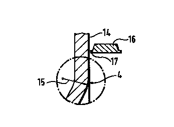
Fig. 1 shows a plan view of a housing part which
forms the side channel,
Fig. 2 shows a section along the line A-B of Fig. 1,
Fig. 3 shows a cylindrical section along the
line C-D of Fig. 1, and
Fig. 4-6 show detail enlargements of the regions
designated IV-VI in Fig. 2 and 3.
The basic construction of the side-channel pump
follows the design disclosed in DE-C974737: two housing
parts enclose a tightly restricted operating space for
an impeller, which space is only expanded in the region
of one of these two housing parts, which is illustrated
in the drawing, in order to form the side channel 1.
The side channel 1 is restricted radially inwards by
the edge 2 and outwards by the edge 3. It begins at
point 4 at the same angular location at which the
suction opening 5, whose outline is indicated in
Fig. 1 by dash-dotted lines, begins radially further
inwards at point 6. The suction opening is situated in
the other housing part, which is not illustrated in the
drawing. In the region of this suction opening the side
channel expands with an appropriately sloping profile
of its inner edge 7 until, approximately 60-90° after
its beginning, it reaches its final cross section,
which is seen at the top in Fig. 2. It maintains the

CA 02306051 2000-04-11
4
said final cross section as far as the delivery opening
8 through which the medium emerges from the side
channel. The delivery opening is bounded by the side
boundaries 11, 12, by the side-channel bottom 10 and
also by the edge 9 (Fig. 3).
Radially within the inner boundary edge 2,
outside the outer boundary edge 3 and between the
starting edge 7 and the final edge 9 of the side
channel, the illustrated housing part forms a planar
front face, which is contiguous to the impeller (vane
16 in Fig. 3) in the fitted pump, and the said housing
part encloses a small sealing gap with its front face
13. This front face also includes the apex region 14
between the final edge 9 and the starting edge 7 of the
side channel. The impeller vanes 16 located in each
case in this region have the task of sealing off the
difference in pressure between the end (delivery
opening 8) and the beginning 4 of the side channel 1 in
close cooperation with this face 14. As indicated in
Figs 3 and 6, in this arrangement the vanes 16, which
are indicated in cross section, pass with their web 17
over the face 14 at a short distance, until they reach
the edge 7 and at this location enter into a medium
which is more or less at rest.
According to the invention, the impact which is
associated therewith is reduced by the rounding of the
edge 4 in accordance with radius 15, this radius
corresponding to the dimensioning rules according to
the invention. Its minimum value amounts to 0.25
[sec/m] times the vane circumferential speed [m/sec]
times the web width in the circumferential direction
[mm] . The factor is preferably between 0.4 and 0. 6. It
should not be greater than 1 because otherwise the
rounding is so large that it reduces the effective
33 length of the side channel in a disadvantageous manner.
The length of the rounding can namely not be increased
at the expense of the circumferential length of the
apex 14, which circumferential length is determined by
AMENDED SHEET

CA 02306051 2000-04-11
the distance between the edge 9 and the beginning 4 of
the side channel, because the sealing mentioned above
has to be effective in this region.
In the case of side-channel pumps which are
5 intended for conveying a relatively large proportion of
gas in the conveying medium, provision is frequently
made in the apex region 14 of a special grooved
depression Which runs obliquely to the circumferential
direction and is generally referred to as an air
displacing channel and is connected to a gas-exit
opening. The known arrangement and function of the said
grooved depression does not need to be explained here.
It suffices to say that the edges of an air-displacing
channel of this type and of a gas-exit opening of this
type may also be rounded in accordance with the
principles described further above for the side
channel. At the delivery opening, the edge 9 is
likewise rounded on the side facing the impeller, as
can be seen .in Fig. 5.
The circumferential distance between that point
of the edge 9 which lies furthest to the rear in the
circumferential direction and the beginning 4 of the
side channel corresponds at least to the spacing of 2.5
vanes.
Tt is further revealed in Fig. 3 that the
bottom of the side channel 1 is lowered a little in the
region 18 shortly before the delivery opening 8, in
order thereby to make it possible for the free cross
section between the edges 9, 10, 11, 12 adjoining the
delivery opening not to be smaller than in the
remaining part of the side channel 1. The lowered
portion 18 only begins shortly before the delivery
opening, namely at a distance from it lying in the
order of magnitude of the height or width of the side
channel.
AMENDED SHEET

Representative Drawing
A single figure which represents the drawing illustrating the invention.
Administrative Status

2024-08-01:As part of the Next Generation Patents (NGP) transition, the Canadian Patents Database (CPD) now contains a more detailed Event History, which replicates the Event Log of our new back-office solution.

Please note that "Inactive:" events refers to events no longer in use in our new back-office solution.

For a clearer understanding of the status of the application/patent presented on this page, the site Disclaimer , as well as the definitions for Patent , Event History , Maintenance Fee  and Payment History  should be consulted.

Event History

Description Date
Application Not Reinstated by Deadline 2003-11-10
Time Limit for Reversal Expired 2003-11-10
Deemed Abandoned - Failure to Respond to Maintenance Fee Notice 2002-11-12
Letter Sent 2002-01-28
Amendment Received - Voluntary Amendment 2002-01-09
Request for Examination Received 2002-01-09
All Requirements for Examination Determined Compliant 2002-01-09
Request for Examination Requirements Determined Compliant 2002-01-09
Inactive: Cover page published 2000-06-21
Inactive: First IPC assigned 2000-06-11
Inactive: Notice - National entry - No RFE 2000-06-02
Letter Sent 2000-06-02
Application Received - PCT 2000-05-29
Application Published (Open to Public Inspection) 1999-05-20

Abandonment History

Abandonment Date Reason Reinstatement Date
2002-11-12

Maintenance Fee

The last payment was received on 2001-10-11

Note : If the full payment has not been received on or before the date indicated, a further fee may be required which may be one of the following

  • the reinstatement fee;
  • the late payment fee; or
  • additional fee to reverse deemed expiry.

Please refer to the CIPO Patent Fees web page to see all current fee amounts.

Fee History

Fee Type Anniversary Year Due Date Paid Date
MF (application, 2nd anniv.) - standard 02 1999-11-10 2000-04-11
MF (application, 3rd anniv.) - standard 03 2000-11-10 2000-04-11
Registration of a document 2000-04-11
Basic national fee - standard 2000-04-11
MF (application, 4th anniv.) - standard 04 2001-11-12 2001-10-11
Request for examination - standard 2002-01-09
Owners on Record

Note: Records showing the ownership history in alphabetical order.

Current Owners on Record
STERLING FLUID SYSTEMS (GERMANY) GMBH
Past Owners on Record
PETER FANDREY
Past Owners that do not appear in the "Owners on Record" listing will appear in other documentation within the application.
Documents

To view selected files, please enter reCAPTCHA code :


To view images, click a link in the Document Description column. To download the documents, select one or more checkboxes in the first column and then click the "Download Selected in PDF format (Zip Archive)" or the "Download Selected as Single PDF" button.

List of published and non-published patent-specific documents on the CPD .

If you have any difficulty accessing content, you can call the Client Service Centre at 1-866-997-1936 or send them an e-mail at CIPO Client Service Centre.


Document
Description 
Date
(yyyy-mm-dd) 
Number of pages   Size of Image (KB) 
Representative drawing 2000-06-21 1 4
Claims 2002-01-09 1 40
Description 2002-01-09 6 292
Description 2000-04-11 5 269
Abstract 2000-04-11 1 21
Drawings 2000-04-11 1 37
Claims 2000-04-11 1 44
Cover Page 2000-06-21 1 44
Notice of National Entry 2000-06-02 1 192
Courtesy - Certificate of registration (related document(s)) 2000-06-02 1 115
Acknowledgement of Request for Examination 2002-01-28 1 178
Courtesy - Abandonment Letter (Maintenance Fee) 2002-12-10 1 176
PCT 2000-04-11 10 409
PCT 2000-04-12 5 161