Language selection

Search

Patent 2306494 Summary

Third-party information liability

Some of the information on this Web page has been provided by external sources. The Government of Canada is not responsible for the accuracy, reliability or currency of the information supplied by external sources. Users wishing to rely upon this information should consult directly with the source of the information. Content provided by external sources is not subject to official languages, privacy and accessibility requirements.

Claims and Abstract availability

Any discrepancies in the text and image of the Claims and Abstract are due to differing posting times. Text of the Claims and Abstract are posted:

  • At the time the application is open to public inspection;
  • At the time of issue of the patent (grant).
(12) Patent Application: (11) CA 2306494
(54) English Title: A FLEXIBLE PIPE WITH AN ASSOCIATED END-FITTING
(54) French Title: TUYAU SOUPLE A RACCORD D'EXTREMITE ASSOCIE
Status: Deemed Abandoned and Beyond the Period of Reinstatement - Pending Response to Notice of Disregarded Communication
Bibliographic Data
Abstracts

English Abstract


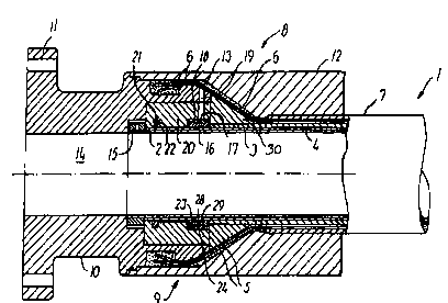
A flexible pressure pipe (1), with an associated end-fitting (9) having an
axially extending through opening (14), is of a non-bonded structure
comprising a number of layers (2, 3, 4, 5, 7) including an extruded polymer
inner lining (3) extending into the through opening (14). In the outer surface
of the end part of the inner lining two annular grooves (23) are formed by
rolling and two opposing grooves (28) are formed in the inner surface of the
lock ring (27). By fitting two circlips (29) into both the grooves (23) in the
inner lining (3) and in the lock ring (27), the latter is attached to the
lining (3), whereafter the lock ring (27) is fitted into a holding groove (17)
in the wall of the through opening (14) of the end-fitting (9). The joint
between the inner lining (3) of the flexible pressure pipe (1) and the end-
fitting (9) is a simple and cheap structure and provides a greater resistance
to axial tensile loads acting on the inner lining (3) than has been know
before.


French Abstract

L'invention concerne un tuyau souple sous pression (1) doté d'un raccord d'extrémité (9) ayant un orifice traversant (14) s'étendant axialement. Ledit tuyau présente une structure non liée comprenant plusieurs couches (2, 3, 4, 5, 7) comportant un revêtement intérieur en polymère extrudé (3) s'étendant dans l'orifice traversant (14). Dans la surface extérieure de la partie d'extrémité du revêtement intérieur, deux rainures annulaires (23) sont formées par laminage et deux rainures opposées (28) sont formées dans la surface intérieure de l'anneau de blocage (27). La mise en place de deux clips circulaires (29) à la fois dans les rainures (23) du revêtement intérieur (3) et celles de l'anneau de blocage (27), permet de fixer ce dernier au revêtement (3), après quoi l'anneau de blocage (27) est logé dans la rainure de maintien (17) de la paroi de l'orifice traversant (14) du raccord d'extrémité (9). Le joint entre le revêtement intérieur (3) du tuyau souple sous pression (1) et le raccord d'extrémité (9) est une structure simple et bon marché et confère une résistance plus élevée aux efforts de tension axiaux agissant sur le revêtement intérieur (3).

Claims

Note: Claims are shown in the official language in which they were submitted.


claims
1. A flexible pressure pipe with an associated end-fitting (9)
having an axially extending through opening (14), where the
pipe is of a non-bonded structure comprising of a number of
layers including an extruded polymer inner lining (3) extending
into the through opening, characterized in that on the outer
surface of the end part of the inner lining (3) at least one
annular groove (23) is formed, a lock ring (16) is attached to
the inner lining (3) by means engaging said annular groove
(23), and the lock ring (16) is attached to the end-fitting
(9) .
2. A flexible pressure pipe according to claim 1, characterized
in that the engagement means for attaching the lock ring (16)
to the at least one annular groove (23) in the outer surface of
the inner lining (3) consists of a generally corresponding
annular rib (25) on the inner surface of the lock ring (16).
3. A flexible pressure pipe according to claim 1, characterized
in that the engagement means for attaching the lock ring (16)
to the at least one annular groove (23) in the outer surface of
the inner lining (3) consists of an opposing groove (28) in the
inner surface of the lock ring (16) and a circlip (29) which is
fitted into both grooves (23;28).
4. A flexible pressure pipe according to claim 1, 2 or 3
characterized in that the at least one annular groove (23) in
the outer surface of the inner lining (3) is formed by rolling.
5. A flexible pressure pipe according to any of claims 1 - 4,
characterized in that the cross-section of the at least one
annular groove (23) in the outer surface of the inner lining
(3) is formed substantially as a segment of circle.

8
6. A flexible pressure pipe according to any of claims 1 - 5,
characterized in that the depth of the at least one annular
groove (23) in the outer surface of the inner lining (3) is
between 0,2 - 0,5 times the thickness of the lining (3).
7. A flexible pressure pipe according to any of claims 1 - 6,
characterized in that the lock ring (16) has a transverse slit
or consists of two or more sectors of circle.
8. A flexible pressure pipe according to any of claims 1 - 7,
characterized in that the lock ring (16) is fitted into a
holding groove (16) in the wall of the through opening (14) of
the end-fitting (9).
9. A flexible pressure pipe according to claim 8, characterized
in that there is a gap between the lock ring (16) and the
holding groove (17), and that this gap is filled with a casting
material (18), e.g. a polymer such as epoxy.
10. A method for assembling a flexible pressure pipe with an
associated end-fitting (9) having an axially extending through
opening (14), where the pipe is of a non-bonded structure
comprising of a number of layers including an extruded polymer
inner lining (3) extending into the through opening (14),
characterized in that the method comprises,
- removing the layers surrounding the lining (3) at an end of
the pipe,
- rolling at least one annular groove (17) in the outer surface
of the end part of the inner lining,
- placing a lock ring (16) consisting of two or more sectors of
a circle around the end part of the lining (3) such that a rib
(25) on the lock ring (16), or a circlip (29) which engages a

9
groove (28) in the lock ring (16), engages the groove (23)
rolled in the outer surface of the end part of the lining,
- securing the lock ring sectors, and
- attaching the lock ring (16) to the end-fitting (9).

Description

Note: Descriptions are shown in the official language in which they were submitted.


CA 02306494 2000-04-13
- 1 .; "; ,I~CT/DIC97/00450
' ' ~.memdei3 0 6 . 10 . 9 9
The invention concerns a flexible pressure pipe with an
associated end-fitting having an axially extending through
opening, where the pipe is of a non-bonded structure comprising
a number of layers including an extruded polymer inner lining
extending into the through opening.
Flexible pressure pipes are used for a variety of applications,
including water supply lines, sewage lines and lines for
transporting chemicals such as liquid ammonia and phosphoric
acid and also high pressure offshore flexible pipes for the oil
and gas industry.
The joint between the inner lining and the end-fitting must be
able to resist the axial tensile load acting on the inner
lining, when the flexible pipe is descending over a great
length, and also such stresses which arise as a consequence of
temperature fluctuations.
Conventionally, said joint is provided by squeezing the inner
lining between an outer conical ring and an inner conical ring
which is pressed in between the inner lining and the carcass of
the pipe. The effect of this squeezing will, however, diminish
gradually as the plasticizer disappears from the plastic
material of the lining.
Another drawback is that temperature stresses can arise in the
joint because the plastic material has a high coefficient of
expansion.
In the document GB 891 611 A is described a tamber-proof
fitting for attachment to the end of a hose having a liner of
substantially plastic material with a braided covering thereon.
Bv assembling an end of the liner is saueezed between an inner
nipple and an outer body member having on the innerside, sharp
ribs which by the scrueezing is forced into the material of the
liner forming complementary share grooves in the liner.
AMENDED SHEET

CA 02306494 2000-04-13
y "p~T,/~25.97/00450
..
" : : : 'Amended .0 6 . 10 . 9 9
This known techniaue cannot be used for pipes havina an inner
carcass which not allows the liner to be saueezed and the
nipple to be screwed in Furthermore, the sharp Grooves in the
liner functions with a danaerous notch effect which is not
acceptable for hiah-auality flexible pressure pipes exposed to
hiah loads.
The object of the invention is to provide a flexible pressure
pipe with an associated end-fitting of the type mentioned in
the opening paragraph in which the joint between the inner
lining of the pipe and the end-fitting is a simple and cheap
structure and provides a greater resistance to axial tensile
loads acting on the inner lining than has been known before.
This is achieved in that on the outer surface of the end part
of the inner lining at least one annular groove is formed, a
lock ring is attached to the inner lining by means engaging
said annular groove, and the lock ring is attached to the end-
fitting, whereby the inner lining can be firmly connected to
the end-fitting in a simple and time efficient manner.
The lock ring can be attached to the annular groove in the
inner lining by a substantially corresponding annular rib on
the inner surface of the lock ring. This embodiment is very
simple.
To compensate for inevitable tolerances of the inner lining and
in the preparation of the joint between the lining and the lock
ring, in another expedient embodiment the lock ring can be
attached to the annular groove in the inner lining by a circlip
which is fitted into both said annular groove in the inner
lining and an opposing groove in the inner surface of the lock
ring.
A~.4ENDED SHEET

CA 02306494 2000-04-13
"P~T/~'K97/00450
..
" ~ ;, ~.m~P~cle'~3 ~0 6 . 10 . 9 9
A particularly strong connection between the inner lining and
the lock ring is obtained when the annular groove in the outer
surface of the inner lining is formed by rolling, such that the
material of the lining will be strengthened and imparted with a
better structure by cold hardening.
For improving the strength of the j oint between the lock ring
and the inner lining, the annular groove in the outer surface
thereof can be formed as a segment of circle and the depth of
the groove can be between 0,2 - 0,5 times the thickness of the
lining.
The lock ring can easily be mounted on the inner lining when it
has a transverse slit or consists of two or more sectors of a
circle.
In a particularly advantageous and strong embodiment, the lock
ring can be fitted into a holding groove formed in the wall of
the through opening of the end-fitting, and for securing this
connection between the lock ring and the holding groove there
may be a gap filled with a casting material, e.g. a polymer
such as epoxy.
The invention also concerns a method for assembling a flexible
pressure pipe with an associated end-fitting having an axially
extending through opening, where the pipe is of a non-bonded
structure comprising of a number of layers including an
extruded polymer inner lining extending into the through
opening. Said method comprises: removing the layers surrounding
the lining at the end of the pipe, rolling at least one annular
groove in the outer surface of the end part of the inner
lining, placing a lock ring consisting of two or more sectors
of a circle around the end part of the lining such that a rib
on the lock ring, or a circlip which engages a groove in the
lock ring, engages the groove rolled in the outer surface of
the end part of the lining, securing the lock ring sectors, and
AMENDED SHEET

CA 02306494 2000-04-13
_ _PCT/D~c97/00450
~meWea 06.10.99
attaching the lock ring to the end-fitting. The method can
advantageously be performed in situ.
The invention will be explained more fully in the following
description, given by way of example, with reference to the
drawings, in which:
Fig. 1 shows, partly in axial section, a typical flexible
pressure pipe,
Fig. 2 shows, in axial section, an assembly of the flexible
pressure pipe shown in fig. 1 and an end-fitting,
Fig. 3 is a perspective view on an enlarged scale of a part of
a first embodiment of a lock ring mounted on an inner lining of
the flexible pipe shown in fig. 1, and
Fig. 4 is a perspective view on an enlarged scale of a part of
a second embodiment of a lock ring mounted on an inner lining
of the flexible pipe shown in fig. 1.
Fig. 1 shows a flexible pressure pipe, which is generally
designated by 1. The pipe is of a non-bonded structure
comprising a number of layers whicr in this embodiment are:
- a carcass 2 of an interlocking structure made from metallic
strips. The carcass serves, in the main, to prevent collapse of
the pipe due to pipe decompression, external pressure, tensile
armour pressure and mechanical crushing loads,
- an inner lining 3 in the form of an extruded polymer layer
for providing internal fluid integrity,
- a pressure armour 4 in the form of structural layers
consisting of helically wound C-shaped metallic strips with a
high lay angle,
AMENDED SHEET

CA 02306494 2000-04-13
~; ' "PCT/D~C97/00450
" ~ r
~mc~i3e3 ros . to . 99
- a tensile armour 5 consisting of a pair of helically counter
wound flat metallic tensile wires 6 with a lay angle typically
between 200 and 600. The tensile armour serves to provide
resistance to axial tensile loads, and
5
- an outer sheath 7 in the form of an extruded polymer for
shielding the structural elements of the pipe from the outer
environment and providing mechanical protection.
Fig. 2 shows an assembly 8 of an end-fitting 9 and the flexible
pressure pipe 1. The end-fitting 9 forms the transition between
the pipe and the connector and for this purpose has a first
part 10 with a connection flange 11, a second part 12, and a
third part 30. The three parts 10; 12; 30 delimit a cavity 13
which partly is substantially cone-shaped. The end-fitting 9
has furthermore a through opening 14 for accommodating an end
of the pipe 1.
When assembling the flexible pressure pipe 1 with the end-
fitting 9 the flat metallic wires 6 of the tensile armour 5 are
led into the cavity 13 in the end-fitting and a casting
material, e.g. epoxy, is injected into the cavity making an
anchoring for the wires.
The carcass 2 is fastened to the end-fitting 9 by means of a
lock nut 15, and to the inner lining 3 by means of a lock ring
16 fitting into an annular groove 17 in the wall of the through
opening 14. The lock ring 16 is in the embodiment shown secured
in the groove 17 by a casting material 18, e.g. epoxy, which is
injected through a hole 19.
A ring 20 provides a stop for the lock nut 15. In the
embodiment shown a sealing ring 21 for tightening the end
fitting 9 and the inner lining 3 is fitted into a groove 22 in
the ring 20.
ANicNOED SHEET

CA 02306494 2000-04-13
6 ' - ~ ,.c~~:T/T.K97/00450
'Am~ndec~'06.10.99
After having removed the layers 4, 5, 7 surrounding the lining
at the end of the pipe, two annular grooves 23 are rolled in
the outer surface of the end part of the inner lining,
whereafter the lock ring 16, which consists of one or more
sectors of circle, is placed around said end part and secured
with a clamp 24.
In the embodiment shown in fig. 3 two annular ribs 25 are
formed on the inner surface of the lock ring 26. The ribs 25
correspond to the annular grooves 23 rolled in the inner lining
3 and therefore engage these grooves firmly.
Fig. 4 shows another embodiment of a lock ring 27 according to
the invention. In this case two annular grooves 28 are formed
on the inner surface of the lock ring 27 and two circlips 29
simultaneously engage the grooves 28 formed in the lock ring
and the groove 23 rolled in the inner lining 3. This
construction can advantageously compensate for tolerances which
are caused by the manufacturing of the inner lining and the
lock ring.
Having thus provided a general discussion, and specific
illustrations by way of examples it is to be understood that no
undue restrictions are to be imposed by reason thereof. Many
other embodiments are imaginable within the scope of the
invention. The specific locking, according to the invention,
between the inner lining 3 of the flexible pressure pipe 1 and
the end-fitting 9 can also be used in combination with other
constructions of the joint between the end-fitting 9 and the
tensile armour wires 6 and the carcass 2, respectively, in
addition to those described above and shown in the figures.
AMENDED SHEET

Representative Drawing
A single figure which represents the drawing illustrating the invention.
Administrative Status

2024-08-01:As part of the Next Generation Patents (NGP) transition, the Canadian Patents Database (CPD) now contains a more detailed Event History, which replicates the Event Log of our new back-office solution.

Please note that "Inactive:" events refers to events no longer in use in our new back-office solution.

For a clearer understanding of the status of the application/patent presented on this page, the site Disclaimer , as well as the definitions for Patent , Event History , Maintenance Fee  and Payment History  should be consulted.

Event History

Description Date
Time Limit for Reversal Expired 2005-10-14
Application Not Reinstated by Deadline 2005-10-14
Deemed Abandoned - Failure to Respond to Maintenance Fee Notice 2004-10-14
Letter Sent 2002-11-15
Request for Examination Received 2002-09-23
Request for Examination Requirements Determined Compliant 2002-09-23
All Requirements for Examination Determined Compliant 2002-09-23
Letter Sent 2000-09-15
Inactive: Correspondence - Transfer 2000-08-02
Inactive: Cover page published 2000-07-13
Inactive: Cover page published 2000-06-30
Inactive: Courtesy letter - Evidence 2000-06-23
Inactive: Correspondence - Transfer 2000-06-21
Inactive: First IPC assigned 2000-06-18
Inactive: Courtesy letter - Evidence 2000-06-13
Inactive: Notice - National entry - No RFE 2000-06-09
Application Received - PCT 2000-05-31
Inactive: Single transfer 2000-05-23
Change of Address or Method of Correspondence Request Received 2000-05-23
Application Published (Open to Public Inspection) 1999-04-22

Abandonment History

Abandonment Date Reason Reinstatement Date
2004-10-14

Maintenance Fee

The last payment was received on 2003-09-22

Note : If the full payment has not been received on or before the date indicated, a further fee may be required which may be one of the following

  • the reinstatement fee;
  • the late payment fee; or
  • additional fee to reverse deemed expiry.

Please refer to the CIPO Patent Fees web page to see all current fee amounts.

Fee History

Fee Type Anniversary Year Due Date Paid Date
Basic national fee - standard 2000-04-13
MF (application, 2nd anniv.) - standard 02 1999-10-14 2000-04-13
Registration of a document 2000-05-23
MF (application, 3rd anniv.) - standard 03 2000-10-16 2000-09-06
MF (application, 4th anniv.) - standard 04 2001-10-15 2001-09-10
MF (application, 5th anniv.) - standard 05 2002-10-14 2002-09-05
Request for examination - standard 2002-09-23
MF (application, 6th anniv.) - standard 06 2003-10-14 2003-09-22
Owners on Record

Note: Records showing the ownership history in alphabetical order.

Current Owners on Record
NKT FLEXIBLES I/S
Past Owners on Record
POUL ERIK BRAAD
Past Owners that do not appear in the "Owners on Record" listing will appear in other documentation within the application.
Documents

To view selected files, please enter reCAPTCHA code :


To view images, click a link in the Document Description column. To download the documents, select one or more checkboxes in the first column and then click the "Download Selected in PDF format (Zip Archive)" or the "Download Selected as Single PDF" button.

List of published and non-published patent-specific documents on the CPD .

If you have any difficulty accessing content, you can call the Client Service Centre at 1-866-997-1936 or send them an e-mail at CIPO Client Service Centre.


Document
Description 
Date
(yyyy-mm-dd) 
Number of pages   Size of Image (KB) 
Representative drawing 2000-07-13 1 19
Abstract 2000-04-13 1 67
Claims 2000-04-13 3 95
Description 2000-04-13 6 275
Drawings 2000-04-13 3 115
Cover Page 2000-07-13 2 77
Notice of National Entry 2000-06-09 1 192
Courtesy - Certificate of registration (related document(s)) 2000-09-15 1 120
Reminder - Request for Examination 2002-06-17 1 118
Acknowledgement of Request for Examination 2002-11-15 1 176
Courtesy - Abandonment Letter (Maintenance Fee) 2004-12-09 1 176
Correspondence 2000-06-09 1 14
Correspondence 2000-05-23 1 59
PCT 2000-04-13 20 776
Correspondence 2000-06-23 1 11